Blueview FN-SV3014 User manual
FN-SV3014
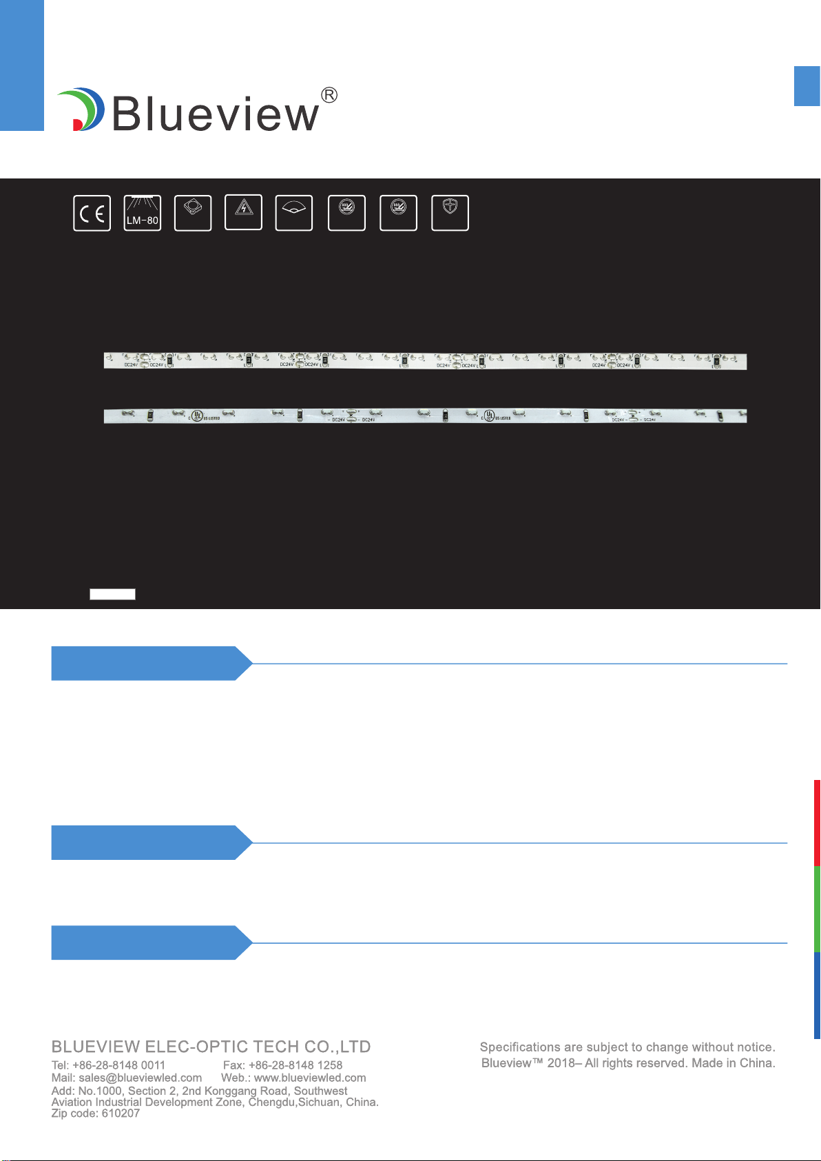
SIDE EMITTING SERIES(SINGLE ROW LED)
Color
Features
Application
1. High quality 3014 LEDs
2. Side illumination
3. High efcacy up to 97lm/W
4. Different arrangements for exible design
5. Excellent uniformity and color consistence
1. Backlight for lightbox
2. Decorative & landscape lighting,Outlines
IP22 IP67
120° 5years
DC
Installation
Fix by 3M self adhesive tape
3014
FN-SV3014-60-12-1
FN-SV3014-120-12-1
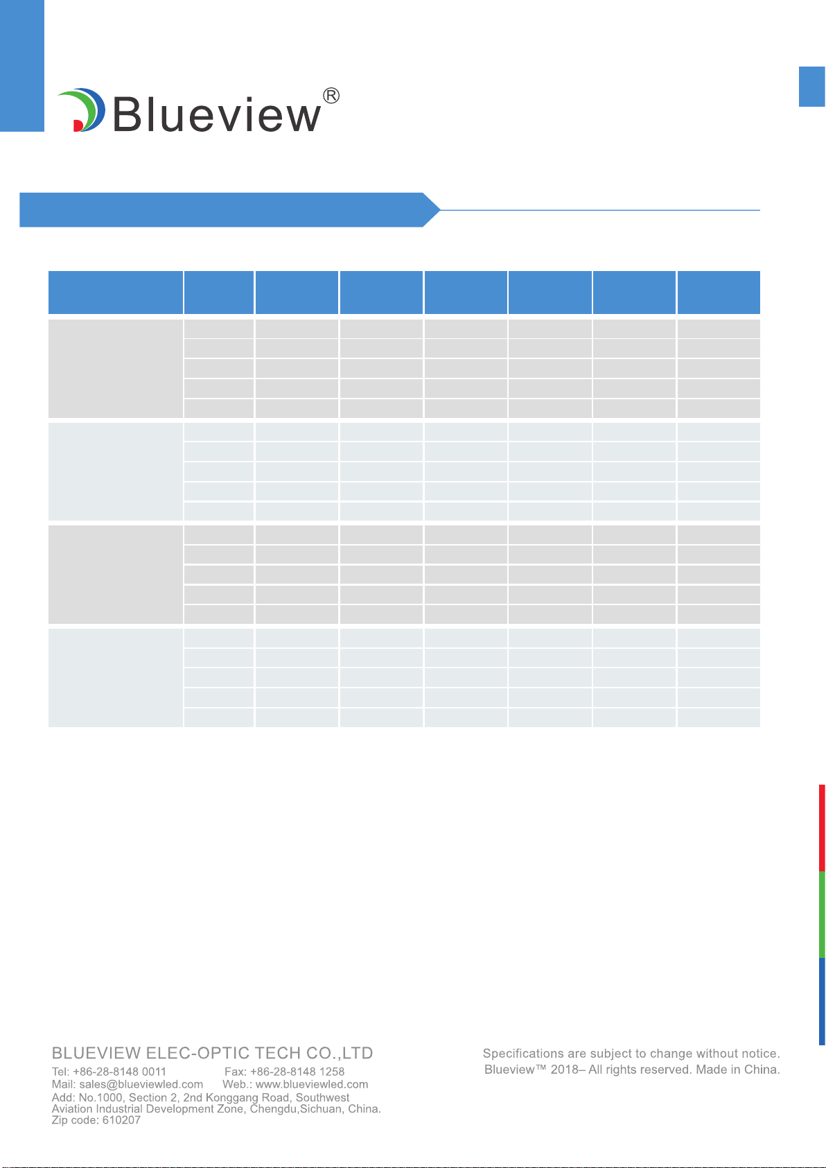
FN-SV3014
SIDE EMITTING SERIES(SINGLE ROW LED)
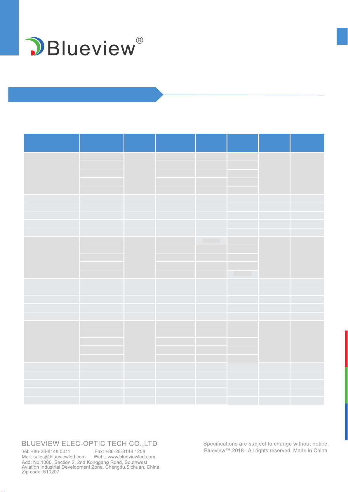
Voltage(V) Power(W/m)
Model No. Luminous Flux
(lm/m) Ra
Color
Temperature(K)
FN-SV3014-60-12-W-1
FN-SV3014-60-12-R-1
FN-SV3014-60-24-R-1
FN-SV3014-120-12-R-1
FN-SV3014-60-12-G-1
FN-SV3014-60-24-G-1
FN-SV3014-120-12-G-1
FN-SV3014-60-12-B-1
FN-SV3014-60-24-B-1
FN-SV3014-120-12-B-1
FN-SV3014-60-12-Y-1
FN-SV3014-60-24-Y-1
FN-SV3014-120-12-Y-1
FN-SV3014-60-12-O-1
FN-SV3014-60-24-O-1
FN-SV3014-120-12-O-1
367 77
332 69
409 85 12 4.8
465 97
335 70
120°
120°
120°
120°
120°
120°
120°
120°
120°
120°
120°
120°
120°
120°
120°
120°
2700
620-625
620-625
620-625
123
129
196
----
----
----
--
--
--
12
24
12
24
12
24
12
24
12
24
4.8
4.8
4.8
4.8
4.8
4.8
4.8
4.8
4.8
4.8
--
--
--
--
--
--
--
--
--
--
--
--
----
----
----
----
----
----
----
----
----
----
----
----
70+
266
280
426
90+
55
58
88
95+
395
416
632
80+
125
132
201
95+
3000
520-525
520-525
520-525
4000
465-470
465-470
465-470
5000
520-525
520-525
520-525
6500
600-605
600-605
600-605
Beam Angle
Optical & Electrical Parameters
Efcacy
(lm/w)
FN-SV3014-60-24-W-1 120°
2700 379 70+ 77
347 90+ 69
420 95+ 84 24 4.8
473 80+ 97
342 95+ 70
3000
4000
5000
6500
FN-SV3014-120-12-W-1
880 70+ 92
640 90+ 67
663 95+ 69 12
12
12
12
12
12
9.6
9.6
9.6
9.6
9.6
9.6
789 80+ 82
635 95+ 66
120°
2700
3000
4000
5000
6500
FN-SV3014
SIDE EMITTING SERIES(SINGLE ROW LED)
Voltage(V) Power(W/m)Model No. Luminous Flux
(lm/m) Ra
Color
Temperature(K)
FN-SV3014-120-24-W-1 120°
892 70+ 95
651 90+ 67
674 95+ 69 24 9.6
793 80+ 85
640 95+ 67
2700
3000
4000
5000
6500
Beam Angle
Optical & Electrical Parameters
Efcacy
(lm/w)
FN-SV3014-120-24-R-1
FN-SV3014-120-24-G-1
FN-SV3014-120-24-B-1
FN-SV3014-120-24-Y-1
FN-SV3014-120-24-O-1
120°
120°
120°
120°
120°
620-625 206 ---- --
--
--
--
--
----
----
----
----
448
93
666
211
520-525
465-470
520-525
600-605
24
24
24
24
24
9.6
9.6
9.6
9.6
9.6
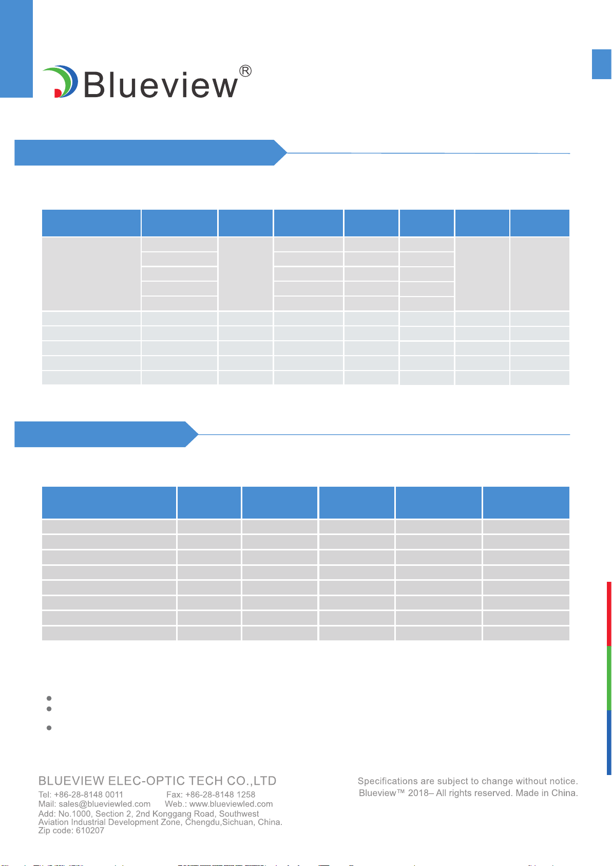
Other Parameters
Model No. LED
Quantity(pcs) Max Run (Single
Feed)(m)
Min Cuttable
length(m)
-25~+60℃
-25~+60℃
-25~+60℃
-25~+60℃
-25~+60℃
-25~+60℃
-25~+60℃
-25~+60℃
-25~+70℃
-25~+70℃
-25~+70℃
-25~+70℃
-25~+70℃
-25~+70℃
-25~+70℃
-25~+70℃
Working
Temperature
Storage
Temperature
FN-SV3014-60-12-W-1 60 2.5 0.05
0.05
0.1
0.1
0.025
0.025
0.05
0.05
2.5
7
7
2
2
3
3
60
60
60
120
120
120
120
FN-SV3014-60-12-R/G/B/Y/O-1
FN-SV3014-60-24-W-1
FN-SV3014-60-24-R/G/B/Y/O-1
FN-SV3014-120-12-W-1
FN-SV3014-120-12-R/G/B/Y/O-1
FN-SV3014-120-24-W-1
FN-SV3014-120-24-R/G/B/Y/O-1
NOTE:
Test environment temperature : 25±2°C.
The above data is typical values. The actual data of each single product may differ from the typical values. The
data is subject to change without notice.
Beam angle refers to the single side LED beam angle.
FN-SV3014
SIDE EMITTING SERIES(SINGLE ROW LED)
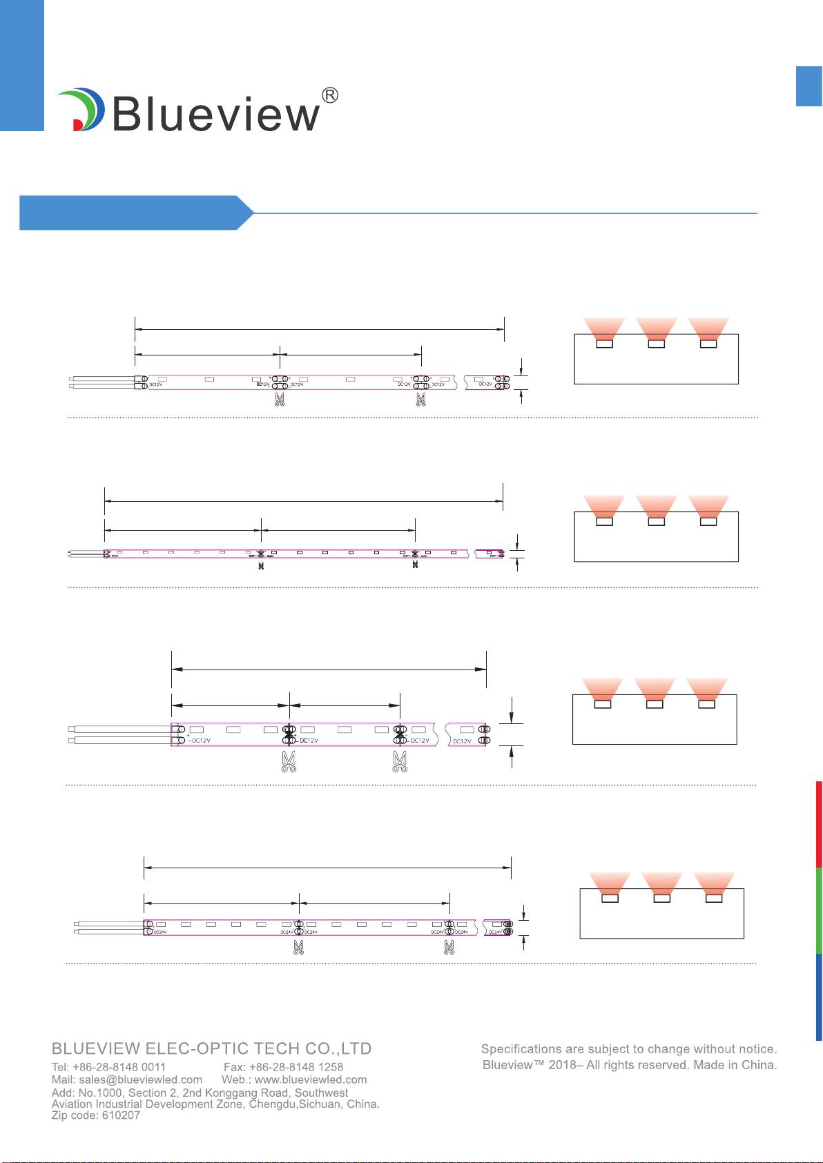
1.FN-SV3014-60-12-W/R/G/B/Y/O-1
2.FN-SV3014-60-24-W/R/G/B/Y/O-1
Prole Drawing Unit mm
502 [19.76]
5 [0.20]
51.5 [2.03] 50 [1.97]
502 [19.76]
5 [0.20]
102 [4.02] 100 [3.94]
Lighting Direction
Lighting Direction
502 [19.76]
51.5 [2.03] 50 [1.97]
5 [0.20]
4.FN-SV3014-120-24-W/R/G/B/Y/O-1
Lighting Direction
3.FN-SV3014-120-12-W/R/G/B/Y/O-1
502 [19.76]
26.5 [1.04] 25 [0.98]
5 [0.20]
Lighting Direction
FN-SV3014
SIDE EMITTING SERIES(SINGLE ROW LED)
Length vs. Power vs. Voltage Drop
Model No.
Working
Length
(m)
Rated
Current
(A)
Rated
Voltage
(DC V)
Rated
Power
(W)
Terminal
Voltage
(DC V)
Tail
Voltage
(DC V)
Voltage
Attenuation
(DC V)
FN-SV3014-60-12-W-1
FN-SV3014-60-24-W-1
1
1
0.4
0.2
12
24
4.8
4.8
11.95
23.97
11.83
23.82
0.12
0.15
2
2
0.8
0.4
12
24
9.6
9.6
11.93
23.94
11.44
23.73
0.49
0.19
3
3
1.2
0.6
12
24
14.4
14.4
11.90
23.92
10.93
23.44
0.97
0.48
4
4
1.6
0.8
12
24
19.2
19.2
11.88
23.91
10.40
23.06
1.48
0.85
5
5
2.0
1.0
12
24
24.0
24.0
11.87
23.89
9.93
22.62
1.94
1.27
FN-SV3014-120-12-W-1
FN-SV3014-120-24-W-1
1 0.4 24 9.6 23.95 23.79 0.16
2
1
2
1.6
0.8
0.8
12
12
24
19.2
9.6
19.2
11.89
11.93
23.91
11.09
11.71
23.30
0.80
0.22
0.61
3
3
2.4
1.2
12
24
27.8
27.8
11.86
23.86
10.39
22.58
1,47
1.28
4
4
3.2
1.6
12
24
38.4
38.4
11.85
23.82
9.75
21.76
2.10
2.06
5
5
4.0
2.0
12
24
48.0
48.0
11.84
23.75
9.23
20.91
2.61
2.84
FN-SV3014
SIDE EMITTING SERIES(SINGLE ROW LED)
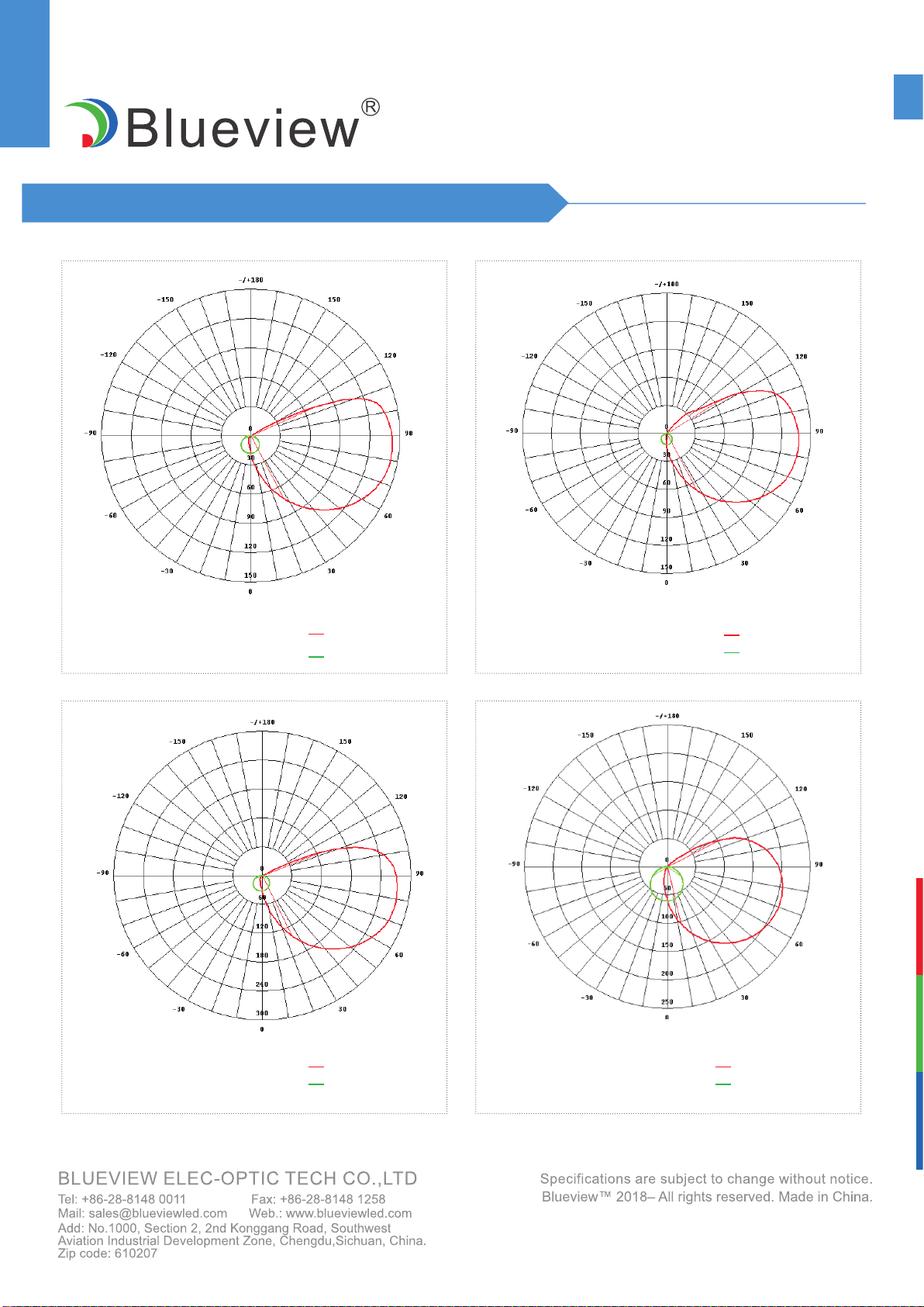
Luminous Intensity Distribution Diagram
AVERAGE BEAM ANGLE(50%):104.6° C0/180,87.7°
Unit:cd
C90/270,121.5°
FN-SV3014-60-12-W-1
AVERAGE BEAM ANGLE(50%):106.6° C0/180,95.3°
Unit:cd
C90/270,117.9°
FN-SV3014-60-24-W-1
AVERAGE BEAM ANGLE(50%):106.1°
C0/180,86.8°
Unit:cd
C90/270,125.3°
FN-SV3014-120-12-W-1
AVERAGE BEAM ANGLE(50%):108.1°
C0/180,104.1°
Unit:cd
C90/270,112.1°
FN-SV3014-120-24-W-1
FN-SV3014
SIDE EMITTING SERIES(SINGLE ROW LED)
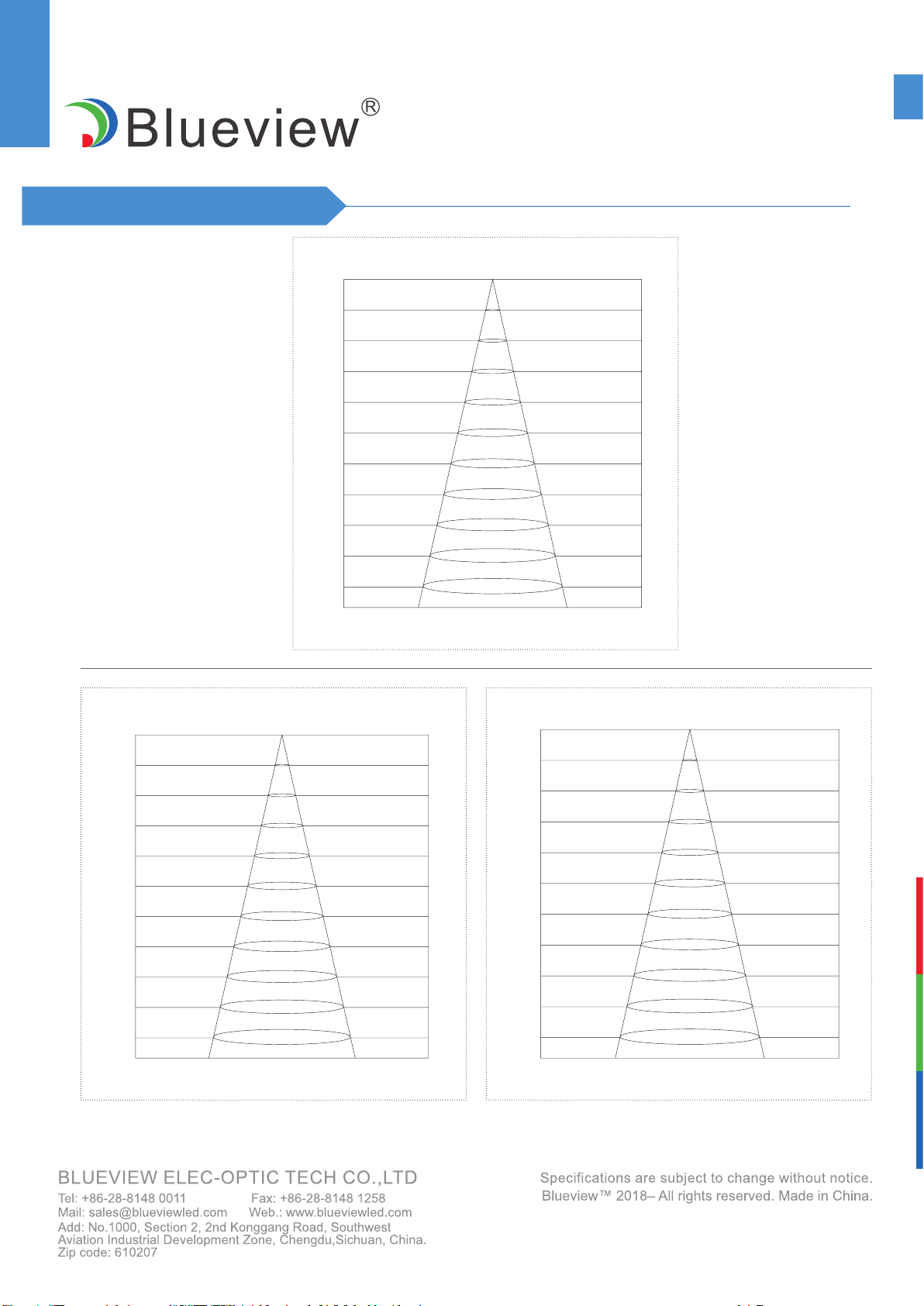
Average Illumination
Luminous Flux output:20.21lm
Height Eavg,Emax Beam Angle:62.54° Diameter
1cm
2cm
3cm
4cm
5cm
6cm
7cm
8cm
9cm
10cm
18307,57856lx
41191,130175lx
164763,520702lx
10298,32544lx
6591,20828lx
4577,14464lx
3363,10627lx
2574,8136lx
2034,6428lx
1648,5207lx
1.21cm
2.43cm
3.64cm
4.86cm
6.07cm
7.29cm
8.50cm
9.72cm
10.93cm
12.15cm
FN-SV3014-60-24-W-1
Luminous Flux output:51.85lm
Height Eavg,Emax Beam Angle:64.65° Diameter
FN-SV3014-120-12-W-1
1cm
2cm
3cm
4cm
5cm
6cm
7cm
8cm
9cm
10cm
43485,112674lx
97842,253516lx
391367,1014062lx
24460,63379lx
15565,40562lx
10871,28168lx
7987,20695lx
6115,15845lx
4832,12519lx
3914,10411lx
1.27cm
2.53cm
3.8cm
5.06cm
6.33cm
7.59cm
8.86cm
10.13cm
11.39cm
12.66cm
Luminous Flux output:101.7lm
Height Eavg,Emax Beam Angle:76.70° Diameter
1cm
2cm
3cm
4cm
5ccm
6cm
7cm
8cm
9cm
10cm
54845,1487391lx
132401,334663lx
493606,1338653lx
30850,83666lx
19744,53546lx
13711,37185lx
10074,27319lx
7713,20916lx
6094,16527lx
4936,13387lx
1.58cm
3.16cm
4.75cm
6.33cm
7.91cm
9.49cm
11.08cm
12.66cm
14.24cm
15.82cm
FN-SV3014-120-24-W-1
Note: The above data are measurements at4000k,please ask the sales for other color temperatures.
FN-SV3014
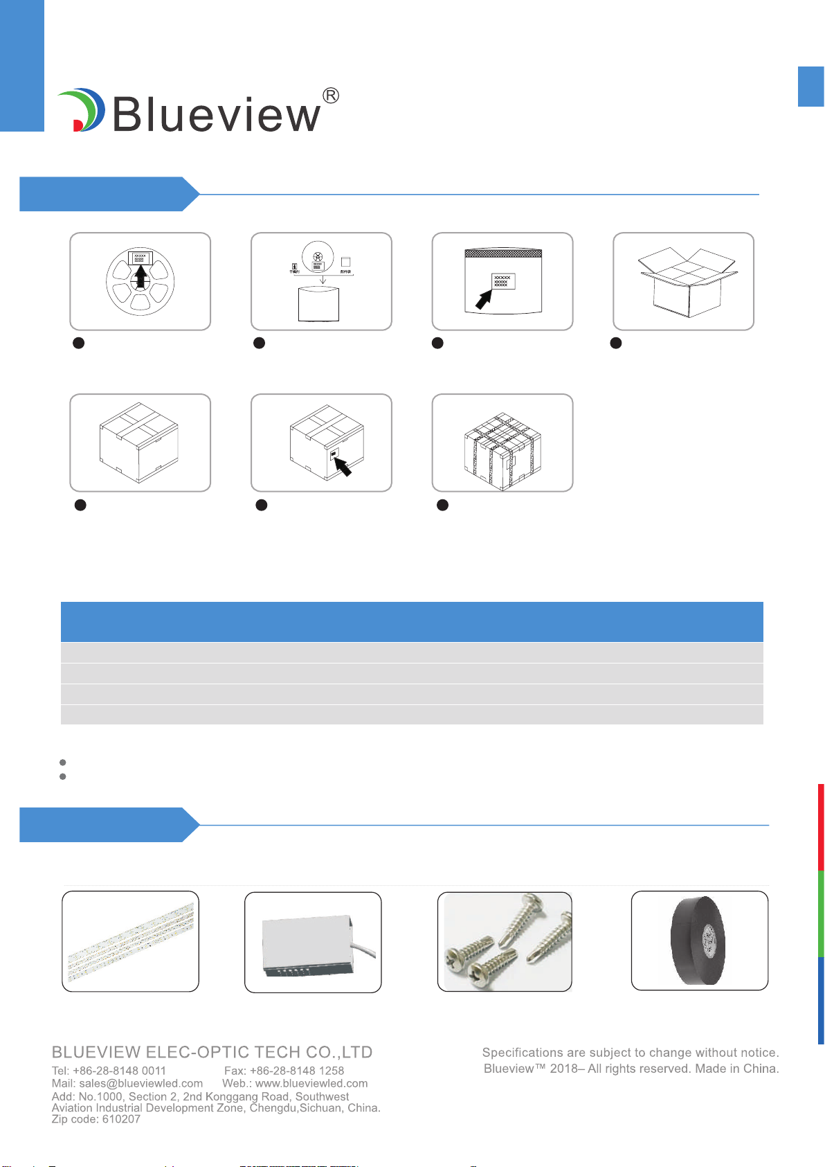
SIDE EMITTING SERIES(SINGLE ROW LED)
Label the reel; Put the packed static
shielding bag into
carton box;
Seal the carton box; Label the box; Use packing belt to
pack. Add edge
protectors if necessary.
Put reel, accessory bag
and desiccant together
into static shielding bag;
Seal and label the static
shielding bag;
1 4
5 6 7
23
Model No.
5000*5
5000*5
5000*5
5000*5
550*400*340
550*400*340
550*400*340
550*400*340
5
5
5
5
140
140
140
140
5.4(1±10%)
5.4(1±10%)
6.1(1±10%)
6.1(1±10%)
11.6(1±10%)
11.6(1±10%)
12.4(1±10%)
12.4(1±10%)
Product Size
(mm)
Carton Size
(mm)
Meter
/Reel
Reel
/Carton
Net Weight
(kg)
Gross Weight
(kg)
Packaging information
Packaging
FN-SV3014-60-12-W/R/G/B/Y/O-1
FN-SV3014-60-24-W/R/G/B/Y/O-1
FN-SV3014-120-12-W/R/G/B/Y/O-1
FN-SV3014-120-24-W/R/G/B/Y/O-1
1 roll(5 m / strip) for a reel, per reel packed in a static shielding bag.
The above quantity and weight are only for the illustrated packaging method. There will be differences
in the quantity and weight with other packaging methods.
Note:
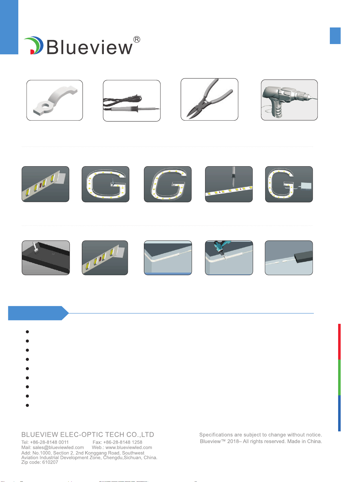
1.Products and Tools
LED power supplyFN-SV3014 Self-tapping screw Electrical tape
Installation
FN-SV3014
SIDE EMITTING SERIES(SINGLE ROW LED)
Clips Electric iron Diagonal pliers Electric drill
2.Installation Methods and Steps
By self adhesive tape
Install with clips
Peel away the self
adhesive tape on the
rear.
Clean the mounting
surface
Peel away the self
adhesive tape on the
rear.
Evenly arrange the
strips with appropriate
space in the light box.
Stick the strips on the
signage accordingly
Connect the strips
with compatible power
supply
Cut off the excess
part based on the
installation position.
Connect main line to
power supply.
Evenly arrange the
strips with appropriate
space in the light box
Use soldering iron
for welding if need
connection.
Attentions
Before installation, check that the product parameters are consistent with the requirements (Seeing product specications or product labels)
Load voltage, current, power and power supply should be matched with the product.
Follow the instructions of wiring diagram (rst connect the load and then the power supply) to avoid short circuit.
Make sure the correct connection of positive and negative poles between led module and power supply. Otherwise, the light will not be on.
Make sure the power cord rmly screwed into the terminal and it should not be pulled out by hands.
The terminal should have insulation,waterproof and anti-corrosive treatment
Take care of being cut by sharp edges.
If the working length exceeded the max run length, make sure to have extra power supply.
If it needs higher current of a LED, make sure having extra cooling.

FN-SV3014
SIDE EMITTING SERIES(SINGLE ROW LED)
Quick Guide Warning
Problems
All LEDs can
not light on.
LEDs can not
light on partly.
Brightness of
LED
is inconsistent
tor insufcient.
LED icker.
Automatic power protection
from the open or short
circuit in output of the power
supply. Fix the short circuit problem.
Correctly connection
Check the power supply
system to x it.
Replace with more powerful
power
Make sure led module working
voltage within ±5% of standard
voltage, or keep balance by
circuit power consumption.
Repair should be operated by a qualied technician, if the external circuit or main line of this product is damaged.
The parameters given in this manual are typical values and for reference only.
All illustrations and drawings in this manual are for reference.
This product is subject to change without notice.
LED lighting products belongs to electronic products, please do recycling treatment according to the relevant WEEE directives.
Reduce the quantities of LED
modules in series connection
to meet requirement.
Fix the short circuit problem.
Wrong connection of power
supply.
Some switching mode power
supplies are not powered.
Power supply line error.
Mistaken wire connection of
some of products
Power overloaded.
Connection point fault. Remove bad connection point.
Replace a new power supply.
Please follow the instructions
Power supply circuit
excessive consumption.
Excessive quantities in series
connection of LED modules.
Switching power supply
failure.
Wrong Installation or use of
products
Reasons
No electric supply.
Solutions Do not disassemble or retrot the light. Do not touch the surface of the
light with a sharp object.
Do not do live-line working during installation,especially for high voltage
product.
Do not use any organic chemical solvents.
Use neutral glass adhesive to x this product and it needs to be dried 4
hours in the open environment after operation.
Treat the ends and the circuit connection points that are not connected
to the main line with insulation,waterproof, and anti-corrosion in the
installation.
Use 20AWG (0.5mm2 or thicker core wire to avoid adverse
consequences caused by overheating, if the power cable need to
lengthen.
Make sure the input voltage meets the requirements and lines are
connected correctly before lighting on.This product is as backlight of
signage, and do not use as general lighting.Series connection within the
max run.
The length of the power cable between the power supply and the led
strip should not exceed 2 meters.Otherwise, large circuit loss will lead
to inconsistent brightness.
Installation, maintenance and repair should be operated by a qualied
technician.
Statements and Recycling
Statements:
Recycling:
Common Faults and Troubleshoot
This manual suits for next models
25
Table of contents


