Blueweld GALAXY 300 User manual

- 1 -
Cod.954241
EN IT FR ES DE RU
PT EL NL HU RO SV
DA NO FI CS SK SL
HR-SR LT ET LV BG PL
MIG-MAG
•
TIG (DC)
•
MMA
(EN) INSTRUCTION MANUAL
(IT) MANUALE D’ISTRUZIONE
(FR) MANUEL D’INSTRUCTIONS
(ES) MANUAL DE INSTRUCCIONES
(DE) BEDIENUNGSANLEITUNG
(RU) РУКОВОДСТВОПОЛЬЗОВАТЕЛЯ
(PT) MANUAL DE INSTRUÇÕES
(EL) ΕΓΧΕΙΡΙΔΙΟΧΡΗΣΗΣ
(NL) INSTRUCTIEHANDLEIDING
(HU) HASZNÁLATI UTASÍTÁS
(RO) MANUALDEINSTRUCŢIUNI
(SV) BRUKSANVISNING
(DA) INSTRUKTIONSMANUAL
(NO) BRUKERVEILEDNING
(FI) OHJEKIRJA
(CS) NÁVODKPOUŽITÍ
(SK) NÁVODNAPOUŽITIE
(SL) PRIROČNIKZNAVODILIZAUPORABO
(HR-SR)
PRIRUČNIKZAUPOTREBU
(LT) INSTRUKCIJŲKNYGELĖ
(ET) KASUTUSJUHEND
(LV) ROKASGRĀMATA
(BG) РЪКОВОДСТВОСИНСТРУКЦИИ
(PL) INSTRUKCJAOBSŁUGI
(EN) Professional MIG-MAG, TIG (DC), MMA welding machines with inverter.
(IT) Saldatrici professionali ad inverter MIG-MAG, TIG (DC), MMA.
(FR) Postes de soudage professionnels à inverseur MIG-MAG, TIG (DC), MMA.
(ES) Soldadoras profesionales con inverter MIG-MAG, TIG (DC), MMA.
(DE) Professionelle Schweißmaschinen MIG-MAG, TIG (DC), MMA mit Invertertechnik.
(RU) ПрофессиональныесварочныеаппаратысинвертеромMIG-MAG,TIG(DC),MMA.
(PT) AparelhosdesoldarprossionaiscomvariadordefreqüênciaMIG-MAG,TIG(DC),MMA.
(EL) ΕπαγγελματικοίσυγκολλητέςμεινβέρτερMIG-MAG,TIG(DC),MMA.
(NL) Professionele lasmachines met inverter MIG-MAG, TIG (DC), MMA.
(HU) ProfesszionálisMIG-MAG,TIG(DC),MMAinverthegesztők.
(RO) AparatedesudurăcuinvertorpentrusuduraMIG-MAG,TIG(DC),MMA,destinateuzuluiprofesional.
(SV) Professionella svetsar med växelriktare MIG-MAG, TIG (DC), MMA.
(DA) Professionelle svejsemaskiner med inverter MIG-MAG, TIG (DC), MMA.
(NO) Profesjonelle sveisebrenner med inverter MIG-MAG, TIG (DC), MMA.
(FI) Ammattihitsauslaitteet vaihtosuuntaajalla MIG-MAG, TIG (DC), MMA.
(CS) ProfesionálnísvařovacíagregátyprosvařováníMIG-MAG,TIG(DC),MMA.
(SK) ProfesionálnezváracieagregátyprezváranieMIG-MAG,TIG(DC),MMA.
(SL) Profesionalni varilni aparati s frekvenènim menjalnikom MIG-MAG, TIG (DC), MMA.
(HR-SR)
Profesionalni stroj za varenje sa inverterom MIG-MAG, TIG (DC), MMA.
(LT) ProfesionalūssuvirinimoaparataisuInverteriuMIG-MAG,TIG(DC),MMA.
(ET) Inverter MIG-MAG, TIG (DC), MMA professionaalsed keevitusaparaadid.
(LV) ProfesionāliemetināšanasaparātiarinvertoruMIG-MAG,TIG(DC),MMAmetināšanai.
(BG) ПрофесионалниинверторниелектроженизазаваряванеMIG-MAG,TIG(DC),MMA.
(PL) Profesjonalne spawarki inwerterowe MIG-MAG, TIG (DC), MMA.

- 2 -
(EN) EXPLANATIONOFDANGER,MANDATORYANDPROHIBITIONSIGNS.
(IT) LEGENDASEGNALIDIPERICOLO,D’OBBLIGOEDIVIETO.
(FR) LÉGENDESIGNAUXDEDANGER,D’OBLIGATIONETD’INTERDICTION.
(ES) LEYENDASEÑALESDEPELIGRO,DEOBLIGACIÓNYPROHIBICIÓN.
(DE) LEGENDEDERGEFAHREN-,GEBOTS-UNDVERBOTSZEICHEN.
(RU) ЛЕГЕНДАСИМВОЛОВБЕЗОПАСНОСТИ,ОБЯЗАННОСТИИЗАПРЕТА.
(PT) LEGENDADOSSINAISDEPERIGO,OBRIGAÇÃOEPROIBIDO.
(EL) ΛΕΖΑΝΤΑΣΗΜΑΤΩΝΚΙΝΔΥΝΟΥ,ΥΠΟΧΡΕΩΣΗΣΚΑΙΑΠΑΓΟΡΕΥΣΗΣ.
(NL) LEGENDESIGNALENVANGEVAAR,VERPLICHTINGENVERBOD.
(HU) AVESZÉLY,KÖTELEZETTSÉGÉSTILTÁSJELZÉSEINEKFELIRATAI.
(RO) LEGENDĂINDICATOAREDEAVERTIZAREAPERICOLELOR,DEOBLIGAREŞI
DEINTERZICERE.
(SV) BILDTEXTSYMBOLERFÖRFARA,PÅBUDOCHFÖRBUD.
(DA) OVERSIGTOVERFARE,PLIGTOGFORBUDSSIGNALER.
(NO) SIGNALERINGSTEKSTFORFARE,FORPLIKTELSEROGFORBUDT.
(FI) VAROITUS,VELVOITUS,JAKIELTOMERKIT.
(CS) VYSVĚTLIVKYKSIGNÁLŮMNEBEZPEČÍ,PŘÍKAZŮMAZÁKAZŮM.
(SK) VYSVETLIVKYKSIGNÁLOMNEBEZPEČENSTVA,PRÍKAZOMAZÁKAZOM.
(SL) LEGENDASIGNALOVZANEVARNOST,ZAPREDPISANOINPREPOVEDANO.
(HR-SR) LEGENDAOZNAKAOPASNOSTI,OBAVEZAIZABRANA.
(LT) PAVOJAUS,PRIVALOMŲJŲIRDRAUDŽIAMŲJŲŽENKLŲPAAIŠKINIMAS.
(ET) OHUD,KOHUSTUSEDJAKEELUD.
(LV) BĪSTAMĪBU,PIENĀKUMUUNAIZLIEGUMAZĪMJUPASKAIDROJUMI.
(BG) ЛЕГЕНДАНАЗНАЦИТЕЗАОПАСНОСТ,ЗАДЪЛЖИТЕЛНИИЗАЗАБРАНА.
(PL) OBJAŚNIENIAZNAKÓWOSTRZEGAWCZYCH,NAKAZUIZAKAZU.
(EN) DANGER OF ELECTRIC SHOCK - (IT) PERICOLO SHOCK ELETTRICO - (FR) RISQUE DE CHOC ÉLECTRIQUE - (ES) PELIGRO DESCARGA ELÉCTRICA - (DE)
STROMSCHLAGGEFAHR - (RU) ОПАСНОСТЬ ПОРАЖЕНИЯ ЭЛЕКТРИЧЕСКИМ ТОКОМ - (PT) PERIGO DE CHOQUE ELÉTRICO - (EL) ΚΙΝΔΥΝΟΣ ΗΛΕΚΤΡΟΠΛΗΞΙΑΣ - (NL)
GEVAARELEKTROSHOCK-(HU)ÁRAMÜTÉSVESZÉLYE-(RO)PERICOLDEELECTROCUTARE-(SV)FARAFÖRELEKTRISKSTÖT-(DA)FAREFORELEKTRISKSTØD-(NO)
FAREFORELEKTRISKSTØT-(FI)SÄHKÖISKUNVAARA-(CS)NEBEZPEČÍZÁSAHUELEKTRICKÝMPROUDEM-(SK)NEBEZPEČENSTVOZÁSAHUELEKTRICKÝMPRÚDOM
-(SL)NEVARNOSTELEKTRIČNEGAUDARA-(HR-SR)OPASNOSTSTRUJNOGUDARA-(LT)ELEKTROSSMŪGIOPAVOJUS-(ET)ELEKTRILÖÖGIOHT-(LV)ELEKTROŠOKA
BĪSTAMĪBA-(BG)ОПАСНОСТОТТОКОВУДАР-(PL)NIEBEZPIECZEŃSTWOSZOKUELEKTRYCZNEGO.
(EN)DANGEROFWELDINGFUMES- (IT) PERICOLOFUMIDISALDATURA-(FR)DANGERFUMÉES DE SOUDAGE -(ES)PELIGROHUMOSDESOLDADURA - (DE) GEFAHR
DERENTWICKLUNGVONRAUCHGASENBEIMSCHWEISSEN-(RU)ОПАСНОСТЬДЫМОВ СВАРКИ-(PT)PERIGODEFUMAÇASDESOLDAGEM-(EL)ΚΙΝΔΥΝΟΣΚΑΠΝΩΝ
ΣΥΓΚΟΛΛΗΣΗΣ-(NL)GEVAARLASROOK-(HU)HEGESZTÉSKÖVETKEZTÉBENKELETKEZETTFÜSTVESZÉLYE-(RO)PERICOLDEGAZEDESUDURĂ-(SV)FARAFÖRRÖKFRÅN
SVETSNING-(DA)FAREP.G.A.SVEJSEDAMPE-(NO)FAREFORSVEISERØYK-(FI)HITSAUSSAVUJENVAARA-(CS)NEBEZPEČÍSVAŘOVACÍCHDÝMŮ-(SK)NEBEZPEČENSTVO
VÝPAROVZOZVÁRANIA-(SL)NEVARNOSTVARILNEGADIMA-(HR-SR)OPASNOSTODDIMAPRILIKOMVARENJA-(LT)SUVIRINIMODŪMŲPAVOJUS-(ET)KEEVITAMISEL
SUITSUOHT-(LV)METINĀŠANASIZTVAIKOJUMUBĪSTAMĪBA-(BG)ОПАСНОСТОТПУШЕКАПРИЗАВАРЯВАНЕ-(PL)NIEBEZPIECZEŃSTWOOPARÓWSPAWALNICZYCH.
(EN) DANGER OF EXPLOSION - (IT) PERICOLO ESPLOSIONE - (FR) RISQUE D’EXPLOSION - (ES) PELIGRO EXPLOSIÓN - (DE) EXPLOSIONSGEFAHR - (RU) ОПАСНОСТЬ
ВЗРЫВА-(PT)PERIGODEEXPLOSÃO-(EL)ΚΙΝΔΥΝΟΣΕΚΡΗΞΗΣ-(NL)GEVAARONTPLOFFING-(HU)ROBBANÁSVESZÉLYE-(RO)PERICOLDEEXPLOZIE-(SV)FARAFÖR
EXPLOSION-(DA)SPRÆNGFARE-(NO)FAREFOREKSPLOSJON-(FI)RÄJÄHDYSVAARA-(CS)NEBEZPEČÍVÝBUCHU-(SK)NEBEZPEČENSTVOVÝBUCHU-(SL)NEVARNOST
EKSPLOZIJE-(HR-SR)OPASNOSTODEKSPLOZIJE-(LT)SPROGIMOPAVOJUS-(ET)PLAHVATUSOHT-(LV)SPRĀDZIENBĪSTAMĪBA-(BG)ОПАСНОСТОТЕКСПЛОЗИЯ-(PL)
NIEBEZPIECZEŃSTWOWYBUCHU.
(EN)WEARINGPROTECTIVECLOTHINGISCOMPULSORY-(IT)OBBLIGOINDOSSAREINDUMENTIPROTETTIVI-(FR)PORTDESVÊTEMENTSDEPROTECTIONOBLIGATOIRE-
(ES)OBLIGACIÓNDELLEVARROPADEPROTECCIÓN-(DE)DASTRAGENVONSCHUTZKLEIDUNGISTPFLICHT-(RU)ОБЯЗАННОСТЬНАДЕВАТЬЗАЩИТНУЮОДЕЖДУ-(PT)
OBRIGATÓRIOOUSODEVESTUÁRIODEPROTEÇÃO-(EL)ΥΠΟΧΡΕΩΣΗΝΑΦΟΡΑΤΕΠΡΟΣΤΑΤΕΥΤΙΚΑΕΝΔΥΜΑΤΑ-(NL)VERPLICHTBESCHERMENDEKLEDIJTEDRAGEN
-(HU)VÉDŐRUHAHASZNÁLATAKÖTELEZŐ-(RO)FOLOSIREAÎMBRĂCĂMINTEIDEPROTECŢIEOBLIGATORIE-(SV)OBLIGATORISKTATTBÄRASKYDDSPLAGG-(DA)PLIGT
TILATANVENDEBESKYTTELSESTØJ-(NO)FORPLIKTELSEÅBRUKEVERNETØY-(FI)SUOJAVAATETUKSENKÄYTTÖPAKOLLISTA-(CS)POVINNÉPOUŽITÍOCHRANNÝCH
PROSTŘEDKŮ-(SK)POVINNÉPOUŽITIEOCHRANNÝCH PROSTRIEDKOV - (SL)OBVEZNOOBLECITEZAŠČITNAOBLAČILA- (HR-SR) OBAVEZNOKORIŠTENJEZAŠTITNE
ODJEĆE-(LT)PRIVALOMADĖVĖTIAPSAUGINĘAPRANGĄ-(ET)KOHUSTUSLIKKANDAKAITSERIIETUST-(LV)PIENĀKUMSĢĒRBTAIZSARGTĒRPUS-(BG)ЗАДЪЛЖИТЕЛНО
НОСЕНЕНАПРЕДПАЗНООБЛЕКЛО-(PL)NAKAZNOSZENIAODZIEŻYOCHRONNEJ.
(EN)WEARINGPROTECTIVEGLOVESISCOMPULSORY-(IT) OBBLIGO INDOSSARE GUANTI PROTETTIVI -(FR)PORTDESGANTSDEPROTECTIONOBLIGATOIRE-(ES)
OBLIGACIÓNDELLEVARGUANTESDEPROTECCIÓN-(DE)DASTRAGENVONSCHUTZHANDSCHUHENISTPFLICHT-(RU)ОБЯЗАННОСТЬНАДЕВАТЬЗАЩИТНЫЕПЕРЧАТКИ
-(PT)OBRIGATÓRIOOUSODELUVASDESEGURANÇA-(EL)ΥΠΟΧΡΕΩΣΗΝΑΦΟΡΑΤΕΠΡΟΣΤΑΤΕΥΤΙΚΑΓΑΝΤΙΑ-(NL)VERPLICHTBESCHERMENDEHANDSCHOENENTE
DRAGEN-(HU)VÉDŐKESZTYŰHASZNÁLATAKÖTELEZŐ-(RO)FOLOSIREAMĂNUŞILORDEPROTECŢIEOBLIGATORIE-(SV)OBLIGATORISKTATTBÄRASKYDDSHANDSKAR
-(DA)PLIGTTILATBRUGEBESKYTTELSESHANDSKER-(NO)FORPLIKTELSEÅBRUKEVERNEHANSKER-(FI)SUOJAKÄSINEIDENKÄYTTÖPAKOLLISTA-(CS)POVINNÉ
POUŽITÍOCHRANNÝCHRUKAVIC-(SK)POVINNÉPOUŽITIEOCHRANNÝCHRUKAVÍC-(SL)OBVEZNONADENITEZAŠČITNEROKAVICE-(HR-SR)OBAVEZNOKORIŠTENJE
ZAŠTITNIHRUKAVICA-(LT)PRIVALOMAMŪVĖTIAPSAUGINESPIRŠTINES-(ET)KOHUSTUSLIKKANDAKAITSEKINDAID-(LV)PIENĀKUMSĢĒRBTAIZSARGCIMDUS-(BG)
ЗАДЪЛЖИТЕЛНОНОСЕНЕНАПРЕДПАЗНИРЪКАВИЦИ-(PL)NAKAZNOSZENIARĘKAWICOCHRONNYCH.
(EN)DANGEROFULTRAVIOLETRADIATIONFROMWELDING-(IT)PERICOLORADIAZIONIULTRAVIOLETTEDASALDATURA-(FR)DANGERRADIATIONSULTRAVIOLETTESDE
SOUDAGE-(ES)PELIGRORADIACIONESULTRAVIOLETAS-(DE)GEFAHRULTRAVIOLETTERSTRAHLUNGENBEIMSCHWEISSEN-(RU)ОПАСНОСТЬУЛЬТРАФИОЛЕТОВОГО
ИЗЛУЧЕНИЯСВАРКИ-(PT)PERIGODERADIAÇÕESULTRAVIOLETASDESOLDADURA-(EL)ΚΙΝΔΥΝΟΣΥΠΕΡΙΩΔΟΥΣΑΚΤΙΝΟΒΟΛΙΑΣΑΠΟΣΥΓΚΟΛΛΗΣΗ-(NL)GEVAAR
ULTRAVIOLET STRALEN VAN HET LASSEN - (HU) HEGESZTÉS KÖVETKEZTÉBEN LÉTREJÖTT IBOLYÁNTÚLI SUGÁRZÁS VESZÉLYE - (RO) PERICOL DE RADIAŢII
ULTRAVIOLETEDELASUDURĂ-(SV)FARAFÖRULTRAVIOLETTSTRÅLNINGFRÅNSVETSNING-(DA)FAREFORULTRAVIOLETTESVEJSESTRÅLER-(NO)FAREFOR
ULTRAFIOLETTSTRÅLNINGUNDERSVEISINGSPROSEDYREN-(FI)HITSAUKSENAIHEUTTAMANULTRAVIOLETTISÄTEILYNVAARA-(CS)NEBEZPEČÍULTRAFIALOVÉHO
ZÁŘENÍZESVAŘOVÁNÍÍ-(SK)NEBEZPEČENSTVOULTRAFIALOVÉHOŽIARENIAZOZVÁRANIA-(SL)NEVARNOSTSEVANJAULTRAVIJOLIČNIHŽARKOVZARADIVARJENJA
-(HR-SR)OPASNOSTODULTRALJUBIČASTIHZRAKAPRILIKOMVARENJA-(LT)ULTRAVIOLETINIOSPINDULIAVIMOSUVIRINIMOMETUPAVOJUS-(ET)KEEVITAMISEL
ERALDUVAULTRAVIOLETTKIIRGUSEOHT-(LV)METINĀŠANASULTRAVIOLETĀIZSTAROJUMABĪSTAMĪBA-(BG)ОПАСНОСТОТУЛТРАВИОЛЕТОВООБЛЪЧВАНЕПРИ
ЗАВАРЯВАНЕ-(PL)NIEBEZPIECZEŃSTWOPROMIENIOWANIANADFIOLETOWEGOPODCZASSPAWANIA.
(EN)DANGEROFFIRE-(IT)PERICOLOINCENDIO-(FR)RISQUED’INCENDIE-(ES)PELIGRODEINCENDIO-(DE)BRANDGEFAHR-(RU)ОПАСНОСТЬПОЖАРА-(PT)PERIGO
DEINCÊNDIO-(EL)ΚΙΝΔΥΝΟΣΠΥΡΚΑΓΙΑΣ-(NL)GEVAARVOORBRAND-(HU)TŰZVESZÉLY-(RO)PERICOLDEINCENDIU-(SV)BRANDRISK-(DA)BRANDFARE-(NO)
BRANNFARE-(FI)TULIPALONVAARA-(CS)NEBEZPEČÍPOŽÁRU-(SK)NEBEZPEČENSTVOPOŽIARU-(SL)NEVARNOSTPOŽARA-(HR-SR)OPASNOSTODPOŽARA-(LT)
GAISROPAVOJUS-(ET)TULEOHT-(LV)UGUNSGRĒKABĪSTAMĪBA-(BG)ОПАСНОСТОТПОЖАР-(PL)NIEBEZPIECZEŃSTWOPOŻARU.
(EN)DANGEROFBURNS-(IT)PERICOLODIUSTIONI-(FR)RISQUEDEBRÛLURES-(ES)PELIGRODEQUEMADURAS-(DE)VERBRENNUNGSGEFAHR-(RU)ОПАСНОСТЬ
ОЖОГОВ-(PT)PERIGODEQUEIMADURAS-(EL)ΚΙΝΔΥΝΟΣΕΓΚΑΥΜΑΤΩΝ-(NL)GEVAARVOORBRANDWONDEN-(HU)ÉGÉSISÉRÜLÉSVESZÉLYE-(RO)PERICOLDE
ARSURI-(SV)RISKFÖRBRÄNNSKADA-(DA)FAREFORFORBRÆNDINGER-(NO)FAREFORFORBRENNINGER-(FI)PALOVAMMOJENVAARA-(CS)NEBEZPEČÍPOPÁLENIN
-(SK)NEBEZPEČENSTVOPOPÁLENÍN-(SL)NEVARNOSTOPEKLIN-(HR-SR)OPASNOSTODOPEKLINA-(LT)NUSIDEGINIMOPAVOJUS-(ET)PÕLETUSHAAVADESAAMISE
OHT-(LV)APDEGUMUGŪŠANASBĪSTAMĪBA-(BG)ОПАСНОСТОТИЗГАРЯНИЯ-(PL)NIEBEZPIECZEŃSTWOOPARZEŃ.
(EN) DANGER OF NON-IONISING RADIATION - (IT) PERICOLO RADIAZIONI NON IONIZZANTI - (FR) DANGER RADIATIONS NON IONISANTES - (ES) PELIGRO RADIACIONES NO
IONIZANTES-(DE)GEFAHRNICHTIONISIERENDERSTRAHLUNGEN-(RU)ОПАСНОСТЬНЕИОНИЗИРУЮЩЕЙРАДИАЦИИ-(PT)PERIGODERADIAÇÕESNÃOIONIZANTES
-(EL)ΚΙΝΔΥΝΟΣΜΗΙΟΝΙΖΟΝΤΩΝΑΚΤΙΝΟΒΟΛΙΩΝ-(NL)GEVAARNIETIONISERENDESTRALEN-(HU)NEMINOGENSUGÁRZÁSVESZÉLYE-(RO)PERICOLDERADIAŢII
NEIONIZANTE-(SV)FARAFÖRICKEJONISERANDE-(DA)FAREFORIKKE-IONISERENDESTRÅLER-(NO)FAREFORUJONISERTSTRÅLNING-(FI)IONISOIMATTOMAN
SÄTEILYNVAARA-(CS)NEBEZPEČÍNEIONIZUJÍCÍHOZÁŘENÍ-(SK)NEBEZPEČENSTVONEIONIZUJÚCEHOZARIADENIA-(SL)NEVARNOSTNEJONIZIRANEGASEVANJA
- (HR-SR) OPASNOST NEJONIZIRAJUĆIH ZRAKA - (LT) NEJONIZUOTO SPINDULIAVIMO PAVOJUS - (ET) MITTEIONISEERITUDKIIRGUSTE OHT - (LV) NEJONIZĒJOŠA
IZSTAROJUMABĪSTAMĪBA-(BG)ОПАСТНОСТОТНЕЙОНИЗИРАНООБЛЪЧВАНЕ-(PL)ZAGROŻENIEPROMIENIOWANIEMNIEJONIZUJĄCYM.
(EN)GENERALHAZARD-(IT)PERICOLOGENERICO-(FR)DANGERGÉNÉRIQUE-(ES)PELIGROGENÉRICO-(DE)GEFAHRALLGEMEINERART-(RU)ОБЩАЯОПАСНОСТЬ
-(PT)PERIGOGERAL-(EL)ΓΕΝΙΚΟΣΚΙΝΔΥΝΟΣ-(NL)ALGEMEENGEVAAR-(HU)ÁLTALÁNOSVESZÉLY-(RO)PERICOLGENERAL-(SV)ALLMÄNFARA-(DA)ALMENFARE
-(NO)GENERISKFARESTRÅLNING-(FI)YLEINENVAARA-(CS)VŠEOBECNÉNEBEZPEČÍ-(SK)VŠEOBECNÉNEBEZPEČENSTVO-(SL)SPLOŠNANEVARNOST-(HR-SR)
OPĆAOPASNOST-(LT)BENDRASPAVOJUS-(ET)ÜLDINEOHT-(LV)VISPĀRĪGABĪSTAMĪBA-(BG)ОБЩИОПАСТНОСТИ-(PL)OGÓLNENIEBEZPIECZEŃSTWO.
(EN)WARNING:MOVINGPARTS-(IT)ATTENZIONEORGANIINMOVIMENTO-(FR)ATTENTIONORGANESENMOUVEMENT-(ES)ATENCIÓNÓRGANOSENMOVIMIENTO
-(DE)VORSICHTBEWEGUNGSELEMENTE-(RU)ВНИМАНИЕ,ЧАСТИВДВИЖЕНИИ -(PT)CUIDADOÓRGÃOS EMMOVIMENTO-(EL) ΠΡΟΣΟΧΗΟΡΓΑΝΑΣΕΚΙΝΗΣΗ-
(NL)OPGELETORGANENINBEWEGING-(HU)VIGYÁZAT:GÉPALKATRÉSZEKMOZGÁSBANVANNAK-(RO)ATENŢIEPIESEÎNMIŞCARE-(SV)VARNINGFÖRORGANI
RÖRELSE-(DA)PASPÅDELEIBEVÆGELSE-(NO)ADVARSEL:BEVEGELIGEDELER-(FI)VAROLIIKKUVIAOSIA-(CS)POZORNAPOHYBUJÍCÍSESOUČÁSTI-(SK)POZOR
NAPOHYBUJÚCESASÚČASTI-(SL)POZOR,NAPRAVEDELUJEJO-(HR-SR)POZORDIJELOVIUPOKRETU-(LT)DĖMESIO!JUDANČIOSDETALĖS-(ET)TÄHELEPANU!
LIIKUVADMASINAOSAD-(LV)UZMANĪBUKUSTĪGĀSDAĻAS-(BG)ВНИМАНИЕДВИЖЕЩИСЕМЕХАНИЗМИ-(PL)UWAGA:RUCHOMECZĘŚCIMASZYNY.
(EN)MINDYOURHANDS,MOVINGPARTS-(IT)ATTENZIONEALLEMANI,ORGANIINMOVIMENTO-(FR)ATTENTIONAUXMAINS,ORGANESENMOUVEMENT-(ES)ATENCIÓN
ALASMANOS,ÓRGANOSENMOVIMIENTO-(DE)AUFDIEHÄNDEACHTEN,BEWEGUNGSELEMENTE-(RU)ОПАСНОСТЬДЛЯРУК,ЧАСТИВДВИЖЕНИИ-(PT)CUIDADO
COMASMÃOS,ÓRGÃOSEMMOVIMENTO-(EL)ΠΡΟΣΟΧΗΣΤΑΧΕΡΙΑ,ΟΡΓΑΝΑΣΕΚΙΝΗΣΗ-(NL)OPGELETVOORDEHANDEN,ORGANENINBEWEGING-(HU)VIGYÁZATA
KEZEKRE,GÉPALKATRÉSZEKMOZGÁSBANVANNAK-(RO)ATENŢIELAMÂINI,PIESEÎNMIŞCARE-(SV)AKTAHÄNDERNA,ORGANIRÖRELSE-(DA)PASPÅHÆNDERNE,
DELEIBEVÆGELSE-(NO)FORSIKTIGMEDHENDENE,BEVEGELIGEDELER-(FI)SUOJAAKÄDETLIIKKUVILTAOSILTA-(CS)POZORNARUCE,POHYBUJÍCÍSESOUČÁSTI-
(SK)POZORNARUKY,POHYBUJÚCESASÚČASTI-(SL)PAZITENAROKE,NAPRAVEDELUJEJO-(HR-SR)POZORSARUKAMA,DIJELOVIUPOKRETU-(LT)SAUGOTIRANKAS,
JUDANČIOSDETALĖS-(ET)TÄHELEPANUKÄTELE,LIIKUVADMASINAOSAD-(LV)UZMANĪBUKUSTĪGĀSDAĻAS-UZMANĪBUSEKOJIETTAM,LAIROKASNEPIESKARTOS
KUSTĪGAJĀMDAĻĀM-(BG)ВНИМАНИЕПАЗЕТЕРЪЦЕТЕОТДВИЖЕЩИТЕСЕМЕХАНИЗМИ-(PL)CHRONIĆRĘCEPRZEDRUCHOMYMICZĘŚCIAMIMASZYNY.
(EN)DONOTUSETHEHANDLETOHANGTHEWELDINGMACHINE.-(IT)VIETATOUTILIZZARELAMANIGLIACOMEMEZZODISOSPENSIONEDELLASALDATRICE-(FR)
INTERDITD’UTILISERLAPOIGNÉECOMMEMOYENDESUSPENSIONDUPOSTEDESOUDAGE-(ES)SEPROHÍBEUTILIZARLAMANILLACOMOMEDIODESUSPENSIÓN
DELASOLDADORA-(DE)ESISTUNTERSAGT,DENGRIFFALSMITTELZUMAUFHÄNGENDERSCHWEISSMASCHINEZUBENUTZEN-(RU)ЗАПРЕЩЕНОПОДВЕШИВАТЬ
СВАРОЧНЫЙАППАРАТЗАРУЧКУ-(PT)ÉPROIBIDOUTILIZARAMAÇANETACOMOMEIODESUSPENSÃODOAPARELHODESOLDAR-(EL)ΑΠΑΓΟΡΕΥΕΤΑΙΗΧΡΗΣΗ
ΤΗΣΧΕΙΡΟΛΑΒΗΣΣΑΝΜΕΣΟΑΝΥΨΩΣΗΣΤΗΣΣΥΓΚΟΛΛΗΤΗΤΙΚΗΣΣΥΣΚΕΥΗΣ-(NL) DEHANDGREEPMAG NIETWORDENGEBRUIKTOMHET LASAPPARAATAANOP
TEHANGEN-(HU)TILOSAHEGESZTŐGÉPETAFOGANTYÚJÁNÁLFOGVAFELAKASZTANI-(RO)SEINTERZICEFOLOSIREAMÂNERULUICAMIJLOCDESUSŢINEREA
APARATULUIDESUDURĂ-(SV)DETÄRFÖRBJUDETATTANVÄNDAHANDTAGETFÖRATTHÄNGAUPPSVETSEN-(DA)DETERFORBUDTATANVENDEHÅNDREBET
TILATHÆVESVEJSEMASKINEN-(NO)DETERFORBUDTÅBRUKEHÅNDTAKETFORÅHENGESVEISEMASKINENOPP-(FI)ONKIELLETTYÄKÄYTTÄÄKÄSIKAHVAA
HITSAUSLAITTEENRIPUSTUSVÄLINEENÄ-(CS)JEZAKÁZÁNOPOUŽÍVATRUKOJEŤJAKOPROSTŘEDEKKZAVĚŠENÍSVAŘOVACÍHOPŘÍSTROJE-(SK)JEZAKÁZANÉ
VEŠAŤZVÁRACÍPRÍSTROJZARUKOVÄŤ-(SL)ROČAJANESMETEUPORABLJATIZAOBEŠANJEVARILNEGAAPARATA-(HR-SR)ZABRANJENOJEUPOTREBLJAVATI
RUČKU ZA PODIZANJE STROJA ZA VARENJE - (LT) DRAUDŽIAMA NAUDOTI RANKENĄ KAIP PRIEMONĘSUVIRINIMO APARATO SUSTABDYMUI - (ET) ON KEELATUD
RIPUTADAKEEVITUSSEADETKASUTADESSELLEKSKÄEPIDET-(LV)IRAIZLIEGTSIZMANTOTROKTURIMETINĀŠANASAPARĀTAPIEKĀRŠANAI-(BG)ЗАБРАНЕНОЕДА
СЕИЗПОЛЗВАРЪКОХВАТКАТАКАТОСРЕДСТВОЗАОКАЧВАНЕНАЗАВАРЪЧНИЯАПАРАТ-(PL)ZABRANIASIEUŻYWANIAUCHWYTUJAKOŚRODKADOZAWIESZANIA
SPAWARKI.
(EN) EYE PROTECTIONS MUST BE WORN - (IT) OBBLIGO DI INDOSSARE OCCHIALI PROTETTIVI - (FR) PORT DES LUNETTES DE PROTECTION OBLIGATOIRE - (ES)
OBLIGACIÓN DE USAR GAFAS DE PROTECCIÓN - (DE) DAS TRAGEN EINER SCHUTZBRILLE IST PFLICHT - (RU) ОБЯЗАННОСТЬ НОСИТЬ ЗАЩИТНЫЕ ОЧКИ - (PT)
OBRIGAÇÃODEVESTIRÓCULOSDEPROTECÇÃO-(EL)ΥΠΟΧΡΕΩΣΗΝΑΦΟΡΑΤΕΠΡΟΣΤΕΤΕΥΤΙΚΑΓΥΑΛΙΑ-(NL)VERPLICHTDRAGENVANBESCHERMENDEBRIL-(HU)
VÉDŐSZEMÜVEGVISELETEKÖTELEZŐ-(RO)ESTEOBLIGATORIEPURTAREAOCHELARILORDEPROTECŢIE-(SV)OBLIGATORISKTATTANVÄNDASKYDDSGLASÖGON
-(DA)PLIGTTILATANVENDEBESKYTTELSESBRILLER-(NO)DETEROBLIGATORISKÅHAPÅSEGVERNEBRILLEN-(FI)SUOJALASIENKÄYTTÖPAKOLLISTA-(CS)
POVINNOST POUŽÍVÁNÍ OCHRANNÝCH BRÝLÍ - (SK) POVINNOSŤ POUŽÍVANIA OCHRANNÝCH OKULIAROV - (SL) OBVEZNA UPORABA ZAŠČITNIH OČAL - (HR-SR)
OBAVEZNAUPOTREBAZAŠTITNIHNAOČALA- (LT)PRIVALOMADIRBTISUAPSAUGINIAISAKINIAIS -(ET)KOHUSTUS KANDAKAITSEPRILLE-(LV)PIENĀKUMSVILKT
AIZSARGBRILLES-(BG)ЗАДЪЛЖИТЕЛНОДАСЕНОСЯТПРЕДПАЗНИОЧИЛА-(PL)NAKAZNOSZENIAOKULARÓWOCHRONNYCH.

- 3 -
(EN) NO ENTRY FOR UNAUTHORISED PERSONNEL - (IT) DIVIETO DIACCESSO ALLE PERSONE NONAUTORIZZATE - (FR) ACCÈS INTERDITAUX PERSONNES NON
AUTORISÉES - (ES) PROHIBIDO EL ACCESO A PERSONAS NO AUTORIZADAS - (DE) UNBEFUGTEN PERSONEN IST DER ZUTRITT VERBOTEN - (RU) ЗАПРЕТ ДЛЯ
ДОСТУПАПОСТОРОННИХЛИЦ-(PT)PROIBIÇÃODEACESSOÀSPESSOASNÃOAUTORIZADAS-(EL)ΑΠΑΓΟΡΕΥΣΗΠΡΟΣΒΑΣΗΣΣΕΜΗΕΠΙΤΕΤΡΑΜΕΝΑΑΤΟΜΑ-(NL)
TOEGANGSVERBODVOORNIETGEAUTORISEERDEPERSONEN-(HU)FELNEMJOGOSÍTOTTSZEMÉLYEKSZÁMÁRATILOSABELÉPÉS-(RO)ACCESULPERSOANELOR
NEAUTORIZATEESTEINTERZIS-(SV)TILLTRÄDEFÖRBJUDETFÖRICKEAUKTORISERADEPERSONER-(DA)ADGANGFORBUDTFORUVEDKOMMENDE-(NO)PERSONER
SOMIKKEERAUTORISERTEMÅIKKEHAADGANGTILAPPARATEN-(FI)PÄÄSYKIELLETTYASIATTOMILTA-(CS)ZÁKAZVSTUPUNEPOVOLANÝMOSOBÁM-(SK)ZÁKAZ
NEOPRÁVNENÉHO PRÍSTUPU K OSÔB - (SL) DOSTOP PREPOVEDAN NEPOOBLAŠČENIM OSEBAM - (HR-SR) ZABRANA PRISTUPA NEOVLAŠTENIM OSOBAMA - (LT)
PAŠALINIAMSĮEITIDRAUDŽIAMA-(ET)SELLEKSVOLITAMATAISIKUTELONTÖÖALASVIIBIMINEKEELATUD-(LV)NEPIEDEROŠĀMPERSONĀMIEEJAAIZLIEGTA-(BG)
ЗАБРАНЕНЕДОСТЪПЪТНАНЕУПЪЛНОМОЩЕНИЛИЦА-(PL)ZAKAZDOSTĘPUOSOBOMNIEUPOWAŻNIONYM.
(EN)WEARINGAPROTECTIVEMASKISCOMPULSORY-(IT)OBBLIGOUSAREMASCHERAPROTETTIVA-(FR)PORTDUMASQUEDEPROTECTIONOBLIGATOIRE-(ES)
OBLIGACIÓN DE USAR MÁSCARA DE PROTECCIÓN - (DE) DER GEBRAUCH EINER SCHUTZMASKE IST PFLICHT - (RU) ОБЯЗАННОСТЬ ПОЛЬЗОВАТЬСЯ ЗАЩИТНОЙ
МАСКОЙ-(PT)OBRIGATÓRIOOUSODEMÁSCARADEPROTEÇÃO-(EL)ΥΠΟΧΡΕΩΣΗΝΑΦΟΡΑΤΕΠΡΟΣΤΑΤΕΥΤΙΚΗΜΑΣΚΑ-(NL)VERPLICHTGEBRUIKVANBESCHERMEND
MASKER-(HU)VÉDŐMASZKHASZNÁLATAKÖTELEZŐ-(RO)FOLOSIREAMĂŞTIIDEPROTECŢIEOBLIGATORIE-(SV)OBLIGATORISKTATTBÄRASKYDDSMASK-(DA)
PLIGT TILATANVENDE BESKYTTELSESMASKE - (NO) FORPLIKTELSE Å BRUKE VERNEBRILLER - (FI) SUOJAMASKIN KÄYTTÖ PAKOLLISTA - (CS) POVINNÉ POUŽITÍ
OCHRANNÉHOŠTÍTU-(SK)POVINNÉPOUŽITIEOCHRANNÉHOŠTÍTU-(SL)OBVEZNOSTUPORABIZAŠČITNEMASKE-(HR-SR)OBAVEZNOKORIŠTENJEZAŠTITNEMASKE
- (LT) PRIVALOMA UŽSIDĖTI APSAUGINĘ KAUKĘ - (ET) KOHUSTUSLIK KANDA KAITSEMASKI - (LV) PIENĀKUMS IZMANTOTAIZSARGMASKU - (BG) ЗАДЪЛЖИТЕЛНО
ИЗПОЛЗВАНЕНАПРЕДПАЗНАЗАВАРЪЧНАМАСКА.-(PL)NAKAZUŻYWANIAMASKIOCHRONNEJ.
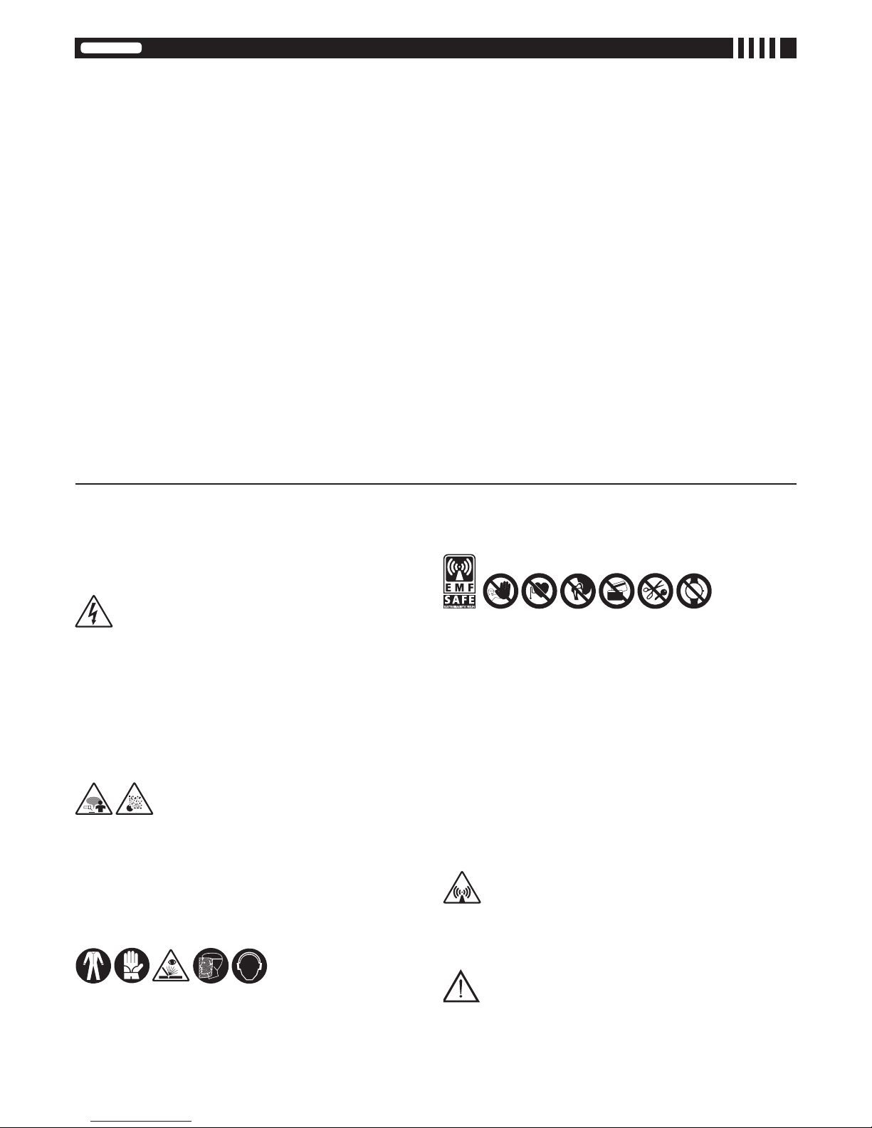
(EN) USERS OF VITAL ELECTRICAL AND ELECTRONIC APPARATUS MUST NEVER USE THE MACHINE - (IT) VIETATO L’USO DELLA MACCHINA AI PORTATORI DI
APPARECCHIATURE ELETTRICHE ED ELETTRONICHE VITALI - (FR) L’UTILISATION DE LA MACHINE EST DÉCONSEILLÉE AUX PORTEURS D’APPAREILS ÉLECTRIQUES OU
ÉLECTRONIQUESMÉDICAUX-(ES)PROHIBIDOELUSODELAMÁQUINAALOSPORTADORESDEAPARATOSELÉCTRICOSYELECTRÓNICOSVITALES-(DE)TRÄGERN
LEBENSERHALTENDER ELEKTRISCHER UND ELEKTRONISCHER GERÄTE IST DER GEBRAUCH DER MASCHINE UNTERSAGT - (RU) ИСПОЛЬЗОВАНИЕ УСТАНОВКИ
ЗАПРЕЩЕНОЛИЦАМ,ИСПОЛЬЗУЮЩИМЭЛЕКТРОННУЮИЭЛЕКТРОАППАРАТУРУОБЕСПЕЧЕНИЯЖИЗНЕДЕЯТЕЛЬНОСТИ-(PT)ÉPROIBIDOOUSODAMÁQUINAAOS
PORTADORESDEAPARELHAGENSELÉCTRICASEELECTRÓNICASVITAIS-(EL)ΑΠΑΓΟΡΕΥΕΤΑΙΗΧΡΗΣΗΤΟΥΜΗΧΑΝΗΜΑΤΟΣΣΕΑΤΟΜΑΠΟΥΦΕΡΟΥΝΗΛΕΚΤΡΙΚΕΣ
ΚΑΙΗΛΕΚΤΡΟΝΙΚΕΣΣΥΣΚΕΥΕΣΖΩΤΙΚΗΣΣΗΜΑΣΙΑΣ-(NL)HETGEBRUIKVANDEMACHINEISVERBODENAANDRAGERSVANELEKTRISCHEENELEKTRONISCHEVITALE
APPARATUUR-(HU)TILOSAGÉPHASZNÁLATAMINDAZOKSZÁMÁRA,AKIKSZERVEZETÉBENÉLETFENNTARTÓELEKTROMOSVAGYELEKTRONIKUSKÉSZÜLÉKVAN
BEÉPÍTVE-(RO)SEINTERZICEFOLOSIREAMAŞINIIDECĂTREPERSOANELEPURTĂTOAREDEAPARATEELECTRICEŞIELECTRONICEVITALE-(SV)FÖRBJUDETFÖR
ANVÄNDAREAVLIVSUPPEHÅLLANDEELEKTRISKAELLERELEKTRONISKAAPPARATERATTANVÄNDADENNAMASKIN-(DA)DETERFORBUDTFORPERSONER,DER
ANVENDER LIVSVIGTIGT ELEKTRISK OG ELEKTRONISK APPARATUR, AT ANVENDE MASKINEN - (NO) DET ER FORBUDT FOR PERSONER SOM BRUKER LIVSVIKTIGE
ELEKTRISKEELLERELEKTRONISKEAPPARATERÅBRUKEMASKINEN-(FI)KONEENKÄYTTÖKIELTOSÄHKÖISTENJAELEKTRONISTENHENKILÖNSUOJALAITTEIDEN
KÄYTTÄJILLE - (CS) ZÁKAZ POUŽITÍ STROJE NOSITELŮM ELEKTRICKÝCH A ELEKTRONICKÝCH ŽIVOTNĚ DŮLEŽITÝCH ZAŘÍZENÍ - (SK) ZÁKAZ POUŽÍVANIA STROJA
OSOBÁM SO ŽIVOTNE DÔLEŽITÝMI ELEKTRICKÝMI A ELEKTRONICKÝMI ZARIADENIAMI - (SL) PREPOVEDANA UPORABA STROJA ZA UPORABNIKE ŽIVLJENJSKO
POMEMBNIHELEKTRIČNIHINELEKTRONSKIHNAPRAV-(HR-SR)ZABRANJENOJEUPOTREBLJAVATISTROJOSOBAMAKOJEIMAJUUGRAĐENEVITALNEELEKTRIČNEILI
ELEKTRONIČKEUREĐAJE-(LT)GRIEŽTAIDRAUDŽIAMASUĮRANGADIRBTIASMENIMS,BESINAUDOJANTIEMSGYVYBIŠKAISVARBIAISELEKTRINIAISARELEKTRONINIAIS
PRIETAISAIS - (ET) SEADET EI TOHI KASUTADA ISIKUD, KES KASUTAVAD MEDITSIINILISI ELEKTRI-JA ELEKTROONIKASEADMEID - (LV) ELEKTRISKO VAI ELEKTRONISKO
MEDICĪNISKOIERĪČULIETOTĀJIEMIRAIZLIEGTSIZMANTOTMAŠĪNU-(BG)ЗАБРАНЕНОЕПОЛЗВАНЕТОНАМАШИНАТАОТЛИЦА,НОСИТЕЛИНАЕЛЕКТРИЧЕСКИИ
ЕЛЕКТРОННИМЕДИЦИНСКИУСТРОЙСТВА-(PL)ZABRONIONEJESTUŻYWANIEURZĄDZENIAOSOBOMSTOSUJĄCYMELEKTRYCZNEIELEKTRONICZNEURZĄDZENIA
WSPOMAGAJĄCEFUNKCJEŻYCIOWE.
(EN)PEOPLEWITHMETALPROSTHESESARENOTALLOWEDTOUSETHEMACHINE-(IT)VIETATOL’USODELLAMACCHINAAIPORTATORIDIPROTESIMETALLICHE-(FR)
UTILISATIONINTERDITEDELAMACHINEAUXPORTEURSDEPROTHÈSESMÉTALLIQUES-(ES)PROHIBIDOELUSODELAMÁQUINAALOSPORTADORESDEPRÓTESIS
METÁLICAS-(DE)TRÄGERNVONMETALLPROTHESENISTDERUMGANGMITDERMASCHINEVERBOTEN-(RU)ИСПОЛЬЗОВАНИЕМАШИНЫЗАПРЕЩАЕТСЯЛЮДЯМ,
ИМЕЮЩИМ МЕТАЛЛИЧЕСКИЕ ПРОТЕЗЫ - (PT) PROIBIDO O USO DA MÁQUINAAOS PORTADORES DE PRÓTESES METÁLICAS - (EL)ΑΠΑΓΟΡΕΥΕΤΑΙ Η ΧΡΗΣΗ ΤΗΣ
ΜΗΧΑΝΗΣΣΕΑΤΟΜΑΠΟΥΦΕΡΟΥΝΜΕΤΑΛΛΙΚΕΣΠΡΟΣΘΗΚΕΣ-(NL)HETGEBRUIKVANDEMACHINEISVERBODENAANDEDRAGERSVANMETALENPROTHESEN-(HU)
TILOSAGÉPHASZNÁLATAFÉMPROTÉZISTVISELŐSZEMÉLYEKSZÁMÁRA-(RO)SEINTERZICEFOLOSIREAMAŞINIIDECĂTREPERSOANELEPURTĂTOAREDEPROTEZE
METALICE-(SV)FÖRBJUDETFÖRPERSONERSOMBÄRMETALLPROTESATTANVÄNDAMASKINEN-(DA)DETERFORBUDTFORPERSONERMEDMETALPROTESERAT
BENYTTEMASKINEN-(NO)BRUKAVMASKINENERIKKETILLATTFORPERSONERMEDMETALLPROTESER-(FI)KONEENKÄYTTÖKIELLETTYMETALLIPROTEESIEN
KANTAJILTA-(CS)ZÁKAZPOUŽITÍSTROJENOSITELŮMKOVOVÝCHPROTÉZ-(SK)ZÁKAZPOUŽITIASTROJAOSOBÁMSKOVOVÝMIPROTÉZAMI-(SL)PREPOVEDANA
UPORABA STROJA ZA NOSILCE KOVINSKIH PROTEZ - (HR-SR) ZABRANJENA UPOTREBA STROJA OSOBAMA KOJE NOSE METALNE PROTEZE - (LT) SU SUVIRINIMO
APARATUDRAUDŽIAMADIRBTIASMENIMS,NAUDOJANTIEMSMETALINIUSPROTEZUS-(ET)SEADETEITOHIKASUTADAISIKUD,KESKASUTAVADMETALLPROTEESE
-(LV)CILVĒKIEMARMETĀLAPROTĒZĒMIRAIZLIEGTSLIETOTIERĪCI-(BG)ЗАБРАНЕНАЕУПОТРЕБАТАНАМАШИНАТАОТНОСИТЕЛИНАМЕТАЛНИПРОТЕЗИ-(PL)
ZAKAZUŻYWANIAURZĄDZENIAOSOBOMSTOSUJĄCYMPROTEZYMETALOWE.
(EN)DONOTWEARORCARRYMETALOBJECTS,WATCHESORMAGNETISEDCARDS-(IT)VIETATOINDOSSAREOGGETTIMETALLICI,OROLOGIESCHEDEMAGNETICHE
- (FR) INTERDICTION DE PORTER DES OBJETS MÉTALLIQUES, MONTRES ET CARTES MAGNÉTIQUES - (ES) PROHIBIDO LLEVAROBJETOS METÁLICOS, RELOJES, Y
TARJETASMAGNÉTICAS-(DE)DASTRAGENVONMETALLOBJEKTEN,UHRENUNDMAGNETKARTENISTVERBOTEN-(RU)ЗАПРЕЩАЕТСЯНОСИТЬМЕТАЛЛИЧЕСКИЕ
ПРЕДМЕТЫ,ЧАСЫИЛИМАГНИТНЫЕПЛАТЫЮ-(PT)PROIBIDOVESTIROBJECTOSMETÁLICOS,RELÓGIOSEFICHASMAGNÉTICAS-(EL)ΑΠΑΓΟΡΕΥΕΤΑΙΝΑΦΟΡΑΤΕ
ΜΕΤΑΛΛΙΚΑ ΑΝΤΙΚΕΙΜΕΝΑ, ΡΟΛΟΓΙΑ ΚΑΙ ΜΑΓΝΗΤΙΚΕΣ ΠΛΑΚΕΤΕΣ - (NL) HET IS VERBODEN METALEN VOORWERPEN, UURWERKEN EN MAGNETISCHE FICHES TE
DRAGEN-(HU)TILOSFÉMTÁRGYAK,KARÓRÁKVISELETEÉSMÁGNESESKÁRTYÁKMAGUKNÁLTARTÁSA-(RO)ESTEINTERZISĂPURTAREAOBIECTELORMETALICE,
A CEASURILOR ŞI A CARTELELOR MAGNETICE - (SV) FÖRBJUDET ATT BÄRA METALLFÖREMÅL, KLOCKOR OCH MAGNETKORT - (DA) FORBUD MOD AT BÆRE
METALGENSTANDE,UREOGMAGNETISKEKORT-(NO)FORBUDTÅHAPÅ SEGMETALLFORMÅL,KLOKKEROGMAGNETISKEKORT-(FI)METALLISTENESINEIDEN,
KELLOJENJAMAGNEETTIKORTTIENMUKANAPITÄMINENKIELLETTY-(CS)ZÁKAZNOŠENÍKOVOVÝCHPŘEDMĚTŮ,HODINEKAMAGNETICKÝCHKARET-(SK)ZÁKAZ
NOSENIAKOVOVÝCHPREDMETOV,HODINIEKAMAGNETICKÝCHKARIET-(SL)PREPOVEDANONOŠENJEKOVINSKIHPREDMETOV,URINMAGNETNIHKARTIC-(HR-SR)
ZABRANJENONOŠENJEMETALNIHPREDMETA,SATOVAIMAGNETSKIHČIPOVA-(LT)DRAUDŽIAMAPRIESAVĘSTURĖTIMETALINIŲDAIKTŲ,LAIKRODŽIŲARMAGNETINIŲ
PLOKŠTELIŲ-(ET)KEELATUDONKANDAMETALLESEMEID,KELLASIDJAMAGENTKAARTE-(LV)IRAIZLIEGTSVILKTMETĀLAPRIEKŠMETUS,PULKSTEŅUSUNŅEMT
LĪDZIMAGNĒTISKĀSKARTES-(BG)ЗАБРАНЕНОЕНОСЕНЕТОНАМЕТАЛНИПРЕДМЕТИ,ЧАСОВНИЦИИМАГНИТНИСХЕМИ-(PL)ZAKAZNOSZENIAPRZEDMIOTÓW
METALOWYCH,ZEGARKÓWIKARTMAGNETYCZNYCH.
(EN)NOTTOBEUSEDBYUNAUTHORISEDPERSONNEL-(IT)VIETATOL’USOALLEPERSONENONAUTORIZZATE-(FR)UTILISATIONINTERDITEAUPERSONNELNON
AUTORISÉ-(ES)PROHIBIDOELUSOAPERSONASNOAUTORIZADAS-(DE)DERGEBRAUCHDURCHUNBEFUGTEPERSONENISTVERBOTEN-(RU)ИСПОЛЬЗОВАНИЕ
ЗАПРЕЩАЕТСЯЛЮДЯМ,НЕИМЕЮЩИМРАЗРЕШЕНИЯ-(PT)PROIBIDOOUSOÀSPESSOASNÃOAUTORIZADAS-(EL)ΑΠΑΓΟΡΕΥΣΗΧΡΗΣΗΣΣΕΜΗΕΠΙΤΕΤΡΑΜΕΝΑ
ΑΤΟΜΑ-(NL)HETGEBRUIKISVERBODENAAN NIET GEAUTORISEERDE PERSONEN - (HU) TILOSAHASZNÁLATAAFEL NEM JOGOSÍTOTTSZEMÉLYEK SZÁMÁRA-
(RO) FOLOSIREA DE CĂTRE PERSOANELE NEAUTORIZATE ESTE INTERZISĂ - (SV) FÖRBJUDET FÖR ICKE AUKTORISERADE PERSONERATT ANVÄNDAAPPARATEN
- (DA) DET ER FORBUDT FOR UVEDKOMMENDE AT ANVENDE MASKINEN - (NO) BRUK ER IKKE TILLATT FOR UAUTORISERTE PERSONER - (FI) KÄYTTÖ KIELLETTY
VALTUUTTAMATTOMILTA HENKILÖILTÄ - (CS) ZÁKAZ POUŽITÍ NEPOVOLANÝM OSOBÁM - (SK) ZÁKAZ POUŽITIA NEPOVOLANÝM OSOBÁM - (SL) NEPOOBLAŠČENIM
OSEBAM UPORABA PREPOVEDANA - (HR-SR) ZABRANJENA UPOTREBA NEOVLAŠTENIM OSOBAMA - (LT) PAŠALINIAMS NAUDOTIS DRAUDŽIAMA - (ET) SELLEKS
VOLITAMATAISIKUTELONSEADMEKASUTAMINEKEELATUD-(LV)NEPILNVAROTĀMPERSONĀMIRAIZLIEGTSIZMANTOTAPARĀTU-(BG)ЗАБРАНЕНОЕПОЛЗВАНЕТО
ОТНЕУПЪЛНОМОЩЕНИЛИЦА-(PL)ZAKAZUŻYWANIAOSOBOMNIEAUTORYZOWANYM.
(EN)Symbolindicatingseparationofelectricalandelectronicappliancesforrefusecollection.Theuserisnotallowedtodisposeoftheseappliances
as solid, mixed urban refuse, and must do it through authorised refuse collection centres. - (IT) Simbolo che indica la raccolta separata delle
apparecchiatureelettricheedelettroniche.L’utentehal’obbligodinonsmaltirequestaapparecchiaturacomeriutomunicipalesolidomisto,madi
rivolgersiaicentridiraccoltaautorizzati.-(FR)Symboleindiquantlacollectedifférenciéedesappareilsélectriquesetélectroniques.L’utilisateurne
peutéliminercesappareilsaveclesdéchetsménagerssolidesmixtes,maisdoits’adresseràuncentredecollecteautorisé.-(ES)Símboloqueindica
larecogidaporseparadodelosaparatoseléctricosyelectrónicos.Elusuariotienelaobligacióndenoeliminaresteaparatocomodesechourbano
sólidomixto,sinodedirigirsealoscentrosderecogidaautorizados.-(DE)SymbolfürdiegetrennteErfassungelektrischerundelektronischerGeräte.
DerBenutzerhatpichtgemäßdafürzusorgen,daßdiesesGerätnichtmitdemgemischterfaßtenfestenSiedlungsabfallentsorgtwird.Stattdessen
mußereinederautorisiertenEntsorgungsstelleneinschalten.-(RU)Символ,указывающийнараздельныйсборэлектрическогоиэлектронного
оборудования.Пользовательнеимеетправавыбрасыватьданноеоборудованиевкачествесмешанноготвердогобытовогоотхода,аобязан
обращатьсявспециализированныецентрысбораотходов.-(PT)Símboloqueindicaareuniãoseparadadasaparelhagenseléctricaseelectrónicas.
Outentetemaobrigaçãodenãoeliminarestaaparelhagemcomolixomunicipalsólidomisto,masdeveprocuraroscentrosderecolhaautorizados.-
(EL)Σύμβολοπουδείχνειτηδιαφοροποιημένησυλλογήτωνηλεκτρικώνκιαηλεκτρονικώνσυσκευών.Οχρήστηςυποχρεούταιναμηνδιοχετεύειαυτή
τησυσκευήσανμικτόστερεόαστικόαπόβλητο,αλλάνααπευθύνεταισεεγκεκριμένακέντρασυλλογής.-(NL)Symbooldatwijstopdegescheiden
inzamelingvanelektrischeenelektronischetoestellen.Degebruikerisverplichtdezetoestellenniettelozenalsgemengdevastestadsafval,maar
moetzichwendentotdegeautoriseerdeophaalcentra.-(HU)Jelölés,melyazelektromoséselektronikusfelszerelésekszelektívhulladékgyűjtését
jelzi.Afelhasználóköteleseztafelszereléstnemavárositörmelékhulladékkalegyüttesengyűjteni,hanemerreengedéllyelrendelkezőhulladékgyűjtő
központhozfordulni.-(RO)Simbolceindicădepozitareaseparatăaaparatelorelectriceşielectronice.Utilizatorulesteobligatsănudepozitezeacest
aparatîmpreunăcu deşeurile solidemixteci să-l predeaîntr-uncentru de depozitareadeşeurilor autorizat. -(SV)Symbol som indikerarseparat
sopsorteringavelektriskaochelektroniskaapparater.Användarenfårintesorteradennaanordningtillsammansmedblandatfasthushållsavfall,utan
måstevändasigtillenauktoriseradinsamlingsstation.-(DA)Symbol,derstårforsærligindsamlingafelektriskeogelektroniskeapparater.Brugeren
harpligttilikkeatbortskaffedetteapparatsomblandet,fastbyaffald;derskalretteshenvendelsetiletautoriseretindsamlingscenter.-(NO)Symbol
somangirseparatsorteringavelektriskeogelektroniskeapparater.Brukerenmåoppfylleforpliktelsenåikkekastebortdetteapparatetsammenmed
vanligehjemmeavfallet,utenhenvendesegtilautoriserteoppsamlingssentraler.-(FI)Symboli,jokailmoittaasähkö-jaelektroniikkalaitteidenerillisen
keräyksen.Käyttäjänvelvollisuusonkääntyävaltuutettujenkeräyspisteidenpuoleeneikävälittäälaitettakunnallisenasekajätteenä.-(CS)Symbol
označující separovaný sběr elektrických a elektronických zařízení. Uživatel je povinen nezlikvidovat toto zařízení jako pevný smíšený komunální
odpad,aleobrátitsesnímnaautorizovanésběrny.-(SK)Symboloznačujúciseparovanýzberelektrickýchaelektronickýchzariadení.Užívateľnesmie
likvidovaťtotozariadenieakopevnýzmiešanýkomunálnyodpad,alejepovinnýdoručiťhodoautorizovanýzberní.-(SL)Simbol,kioznačujeločeno
zbiranjeelektričnihinelektronskihaparatov.Uporabniktegaaparatanesmezavrečikotnavadengospodinjskitrdenodpadek,ampaksemoraobrnitina
pooblaščenecentrezazbiranje.-(HR-SR)Simbolkojioznačavaposebnosakupljanjeelektričnihielektronskihaparata.Korisniknesmijeodložitiovaj
aparatkaoobičankrutiotpad,većsemoraobratitiovlaštenimcentrimazasakupljanje.-(LT)Simbolis,nurodantisatskirųnebenaudojamųelektrinių
irelektroniniųprietaisųsurinkimą.Vartotojasnegaliišmestišiųprietaisųkaipmišriųkietųjųkomunaliniųatliekų,betprivalokreiptisįspecializuotus
atliekųsurinkimocentrus.-(ET)Sümbol,mistähistabelektri-jaelektroonikaseadmeteeraldikogumist.Kasutajakohustuseksonpöördudavolitatud
kogumiskeskustepoolejamittekäsitledasedaaparaatikuimunitsipaalnesegajääde.-(LV)Simbols,kasnorādauzto,kautilizācijairjāveicatsevišķi
nocitāmelektriskajāmunelektroniskajāmierīcēm.Lietotājapienākumsirneizmestšoaparatūrumunicipālajācietoatkritumuizgāztuvē,betnogādāt
topilnvarotajā atkritumu savākšanascentrā. - (BG)Символ,койтоозначаваразделно събиранена електрическатаиелектронна апаратура.
Ползвателятсезадължаваданеизхвърлятазиапаратуракатосмесентвърдотпадъквконтейнеритезасмет,поставениотобщината,атрябва
дасеобърнекъмспециализиранитезатовацентрове-(PL)Symbol,któryoznaczasortowanieodpadówaparaturyelektrycznejielektronicznej.
Zabraniasięlikwidowaniaaparaturyjakomieszanychodpadówmiejskichstałych,obowiązkiemużytkownikajestskierowaniesiędoautoryzowanych
ośrodkówgromadzącychodpady.

- 4 -
INSTRUCTIONSFORUSEANDMAINTENANCE.............................................pag.5
WARNING!BEFOREUSINGTHEWELDINGMACHINEREADTHEINSTRUCTIONMANUALCAREFULLY! EN
ISTRUZIONIPERL’USOELAMANUTENZIONE............................................pag.10
ATTENZIONE!PRIMADIUTILIZZARELASALDATRICELEGGEREATTENTAMENTEILMANUALEDIISTRUZIONE! IT
INSTRUCTIONSD’UTILISATIONETD’ENTRETIEN.......................................pag.16
ATTENTION!AVANTTOUTEUTILISATIONDUPOSTEDESOUDAGE,LIREATTENTIVEMENTLEMANUELD’INSTRUCTIONS! FR
INSTRUCCIONESPARAELUSOYMANTENIMIENTO..................................pág.22
ATENCIÓN!ANTESDEUTILIZARLASOLDADORALEERATENTAMENTEELMANUALDEINSTRUCCIONES! ES
BETRIEBS-UNDWARTUNGSANLEITUNG.........................................................s.28
ACHTUNG!VORGEBRAUCHDERSCHWEISSMASCHINELESENSIEBITTESORGFÄLTIGDIEBETRIEBSANLEITUNG! DE
ИНСТРУКЦИИПОРАБОТЕИТЕХОБСЛУЖИВАНИЮ..................................стр.34
ВНИМАНИЕ!ПЕРЕДТЕМ,КАКИСПОЛЬЗОВАТЬМАШИНУ,ВНИМАТЕЛЬНОПРОЧИТАТЬРУКОВОДСТВОПОЛЬЗОВАТЕЛЯ! RU
INSTRUÇÕESDEUSOEMANUTENÇÃO.......................................................pág.40
CUIDADO!ANTESDEUTILIZARAMÁQUINADESOLDALERCUIDADOSAMENTEOMANUALDEINSTRUÇÕES! PT
ΟΔΗΓΙΕΣΧΡΗΣΗΣΚΑΙΣΥΝΤΗΡΗΣΗΣ.............................................................σελ.46
ΠΡΟΣΟΧΗ!ΠΡΙΝΧΡΗΣΙΜΟΠΟΙΗΣΕΤΕΤΟΣΥΓΚΟΛΛΗΤΗΔΙΑΒΑΣΤΕΠΡΟΣΕΚΤΙΚΑΤΟΕΓΧΕΙΡΙΔΙΟΧΡΗΣΗΣ! EL
INSTRUCTIES VOOR HET GEBRUIK EN HET ONDERHOUD........................pag.52
OPGELET!VOORDATMENDELASMACHINEGEBRUIKTMOETMENAANDACHTIGDEINSTRUCTIEHANDLEIDINGLEZEN! NL
HASZNÁLATI UTASÍTÁSOK ÉS KARBANTARTÁSISZABÁLYOK...............oldal58
FIGYELEM:AHEGESZTŐGÉPHASZNÁLATÁNAKMEGKEZDÉSEELŐTTOLVASSAELFIGYELMESENAHASZNÁLATIUTASÍTÁST!
HU
INSTRUCŢIUNIDEFOLOSIREŞIÎNTREŢINERE...........................................pag.64
ATENŢIE:CITIŢICUATENŢIEACESTMANUALDEINSTRUCŢIUNIÎNAINTEDEFOLOSIREAAPARATULUIDESUDURĂ! RO
INSTRUKTIONERFÖRANVÄNDNINGOCHUNDERHÅLL.............................sid.70
VIKTIGT!LÄSBRUKSANVISNINGENNOGGRANTINNANNIANVÄNDERSVETSEN! SV
BRUGS-OGVEDLIGEHOLDELSESVEJLEDNING...........................................sd.75
GIVAGT!LÆSBRUGERVEJLEDNINGENOMHYGGELIGT,FØRMASKINENTAGESIBRUG! DA
INSTRUKSER FOR BRUK OG VEDLIKEHOLD...................................................s.80
ADVARSEL!FØRDUBRUKERSVEISEBRENNERENMÅDULESEBRUKERVEILEDNINGENNØYE! NO
KÄYTTÖ-JAHUOLTO-OHJEET...........................................................................s.85
HUOM!ENNENHITSAUSKONEENKÄYTTÖÄLUEHUOLELLISESTIKÄYTTÖOHJEKIRJA! FI
NÁVODKPOUŽITÍAÚDRŽBĚ..........................................................................str.90
UPOZORNĚNÍ:PŘEDPOUŽITÍMSVAŘOVACÍHOPŘÍSTROJESIPOZORNĚPŘEČTĚTENÁVODKPOUŽITÍ! CS
NÁVODNAPOUŽITIEAÚDRŽBU.....................................................................str.96
UPOZORNENIE:PREDPOUŽITÍMZVÁRACIEHOPRÍSTROJASIPOZORNEPREČÍTAJTENÁVODNAPOUŽITIE! SK
NAVODILAZAUPORABOINVZDRŽEVANJE.................................................str.102
POZOR:PREDUPORABOVARILNENAPRAVEPOZORNOPREBERITEPRIROČNIKZNAVODILIZAUPORABO! SL
UPUTSTVAZAUPOTREBUISERVISIRANJE.................................................str.107
POZOR:PRIJEUPOTREBESTROJAZAVARENJEPOTREBNOJEPAŽLJIVOPROČITATIPRIRUČNIKZAUPOTREBU! HR SR
EKSPLOATAVIMOIRPRIEŽIŪROSINSTRUKCIJOS.....................................psl.112
DĖMESIO:PRIEŠNAUDOJANTSUVIRINIMOAPARATĄ,ATIDŽIAIPERSKAITYTIINSTRUKCIJŲKNYGELĘ! LT
KASUTUSJUHENDIDJAHOOLDUS.................................................................lk.117
TÄHELEPANU:ENNEKEEVITUSAPARAADIKASUTAMISTLUGEGEKASUTUSJUHISEDTÄHELEPANELIKULTLÄBI! ET
IZMANTOŠANASUNTEHNISKĀSAPKOPESROKASGRĀMATA................lpp.122
UZMANĪBU:PIRMSMETINĀŠANASAPARĀTAIZMANTOŠANASUZMANĪGIIZLASIETROKASGRĀMATU! LV
ИНСТРУКЦИИЗАУПОТРЕБАИПОДДРЪЖКА..........................................стр.128
ВНИМАНИЕ:ПРЕДИДАИЗПОЛЗВАТЕЕЛЕКТРОЖЕНА,ПРОЧЕТЕТЕВНИМАТЕЛНОРЪКОВОДСТВОТОСИНСТРУКЦИИЗАПОЛЗВАНЕ.
BG
INSTRUKCJEOBSŁUGIIKONSERWACJI.....................................................str.134
UWAGA:PRZEDROZPOCZĘCIEMSPAWANIANALEŻYUWAŻNIEPRZECZYTAĆINSTRUKCJĘOBSŁUGI! PL
(EN) GUARANTEE AND CONFORMITY- (IT) GARANZIA E CONFORMITÀ - (FR) GARANTIE ET CONFORMITÉ - (ES) GARANTÍAY CONFORMIDAD - (DE) GARANTIE UND
KONFORMITÄT-(RU)ГАРАНТИЯИСООТВЕТСТВИЕ-(PT)GARANTIAECONFORMIDADE-(EL)ΕΓΓΥΗΣΗΚΑΙΣΥΜΜΟΡΦΩΣΗΣΤΙΣΔΙΑΤΑΞΕΙΣ-(NL)GARANTIE
ENCONFORMITEIT-(HU)GARANCIAÉSAJOGSZABÁLYIELŐÍRÁSOKNAKVALÓMEGFELELŐSÉG-(RO)GARNŢIEŞICONFORMITATE-(SV)GARANTIOCH
ÖVERENSSTÄMMELSE - (DA) GARANTI OG OVERENSSTEMMELSESERKLÆRING - (NO) GARANTI OG KONFORMITET - (FI) TAKUU JA VAATIMUSTENMUKAISUUS’
- (CS) ZÁRUKA A SHODA - (SK) ZÁRUKA A ZHODA - (SL) GARANCIJA IN UDOBJE - (HR-SR) GARANCIJA I SUKLADNOST - (LT) GARANTIJA IR ATITIKTIS - (ET)
GARANTIIJAVASTAVUS-(LV)GARANTIJAUNATBILSTĪBA-(BG)ГАРАНЦИЯИСЪОТВЕТСТВИЕ-(PL)GWARANCJAIZGODNOŚĆ.....................................150-152

- 5 -
CONTINUOUSWIREWELDINGMACHINEFORMIG-MAGANDFLUX,TIG,MMA
WELDINGFORPROFESSIONALANDINDUSTRIALUSE.
Note:Theterm“weldingmachine”willbeusedinthetextthatfollows.
1.GENERALSAFETYCONSIDERATIONSFORARCWELDING
The operator should be properly trained to use the welding machine safely
andshouldbeinformedabouttherisksrelatedtoarcweldingprocedures,the
associatedprotectionmeasuresandemergencyprocedures.
(Pleaserefertotheapplicablestandard”EN60974-9:Arcweldingequipment.
Part9:InstallationandUse).
- Avoiddirectcontactwiththeweldingcircuit:theno-loadvoltagesuppliedby
theweldingmachinecanbedangerousundercertaincircumstances.
- When the welding cables are being connected or checks and repairs are
carried out the welding machine should be switched off and disconnected
fromthepowersupplyoutlet.
- Switchofftheweldingmachineanddisconnectitfromthepowersupplyoutlet
beforereplacingconsumabletorchparts.
- Maketheelectricalconnectionsandinstallationaccordingtothesafetyrules
andlegislationinforce.
- Theweldingmachineshouldbeconnectedonlyandexclusivelytoapower
sourcewiththeneutralleadconnectedtoearth.
- Make sure that the power supply plug is correctly connected to the earth
protectionoutlet.
- Donotusetheweldingmachineindamporwetplacesanddonotweldinthe
rain.
- Donotusecableswithworninsulationorlooseconnections.
- Donotweldoncontainersorpipingthatcontainsorhascontainedammable
liquidorgaseousproducts.
- Donotoperateonmaterialscleanedwithchlorinatedsolventsornearsuch
substances.
- Donotweldoncontainersunderpressure.
- Removeallammablematerials(e.g.wood,paper,ragsetc.)fromtheworking
area.
- Provideadequateventilationorfacilitiesfortheremovalofweldingfumesnear
thearc;asystematicapproachisneededinevaluatingtheexposurelimitsfor
theweldingfumes,whichwilldependontheircomposition,concentrationand
thelengthofexposureitself.
- Keep the gas bottle (if used) away from heat sources, including direct
sunlight.
- Useelectricinsulationthatis suitable forthetorch,theworkpieceand any
metalpartsthatmaybeplacedonthegroundandnearby(accessible).
Thiscannormallybedonebywearinggloves,footwear,headprotectionand
clothingthataresuitableforthepurposeandbyusinginsulatingboardsor
mats.
- Alwaysprotectyoureyeswiththerelativelters,whichmustcomplywithUNI
EN169orUNIEN379,mountedonmasksorusehelmetsthatcomplywithUNI
EN175.
Use the relative re-resistant clothing (compliant with UNI EN 11611) and
weldinggloves(compliantwithUNIEN12477)withoutexposingtheskintothe
ultravioletandinfraredraysproducedbythearc;theprotectionmustextend
to other people who are near the arc by way of screens or non-reective
sheets.
- Noise:Ifthedailypersonalnoiseexposure(LEPd)isequaltoorhigherthan85
dB(A)becauseofparticularlyintensiveweldingoperations,suitablepersonal
protectivemeansmustbeused(Tab.1).
- Theowoftheweldingcurrentgenerateselectromagneticelds(EMF)around
theweldingcircuit.
Electromagneticeldscaninterferewithcertainmedicalequipment(e.g.Pace-
makers,respiratoryequipment,metallicprosthesesetc.).
Adequateprotectivemeasuresmustbeadoptedforpersonswiththesetypesof
medicalapparatus.Forexample,theymustbeforbiddenaccesstotheareain
whichweldingmachinesareinoperation.
Thisweldingmachineconforms to technicalproductstandardsfor exclusive
useinanindustrialenvironmentforprofessionalpurposes.Itdoesnotassure
compliancewiththebasiclimitsrelativetohumanexposuretoelectromagnetic
eldsinthedomesticenvironment.
Theoperatormustadoptthefollowingproceduresinordertoreduceexposure
toelectromagneticelds:
- Fastenthetwoweldingcablesasclosetogetheraspossible.
- Keepheadandtrunkasfarawayaspossiblefromtheweldingcircuit.
- Neverwindweldingcablesaroundthebody.
- Avoidweldingwiththebodywithintheweldingcircuit.Keepbothcableson
thesamesideofthebody.
- Connecttheweldingcurrentreturncabletothepiecebeingwelded,asclose
aspossibletotheweldingjoint.
- Donotweldwhilecloseto,sittingonorleaningagainsttheweldingmachine
(keepatleast50cmawayfromit).
- Do not leave objects in ferromagnetic material in proximity of the welding
circuit.
- Minimumdistanced=20cm(Fig.R).
- ClassAequipment:
Thisweldingmachineconforms to technicalproductstandardsfor exclusive
use in an industrial environment and for professional purposes. It does not
assure compliance with electromagnetic compatibility in domestic dwellings
and in premises directly connected to a low-voltage power supply system
feedingbuildingsfordomesticuse.
EXTRA PRECAUTIONS
- WELDINGOPERATIONS:
- Inenvironmentswithincreasedriskofelectricshock;
- Inconnedspaces;
- Inthepresenceofammableorexplosivematerials;
MUSTBEevaluatedinadvancebyan“Expertsupervisor”andmustalways
ENGLISH INDEX
1.GENERALSAFETYCONSIDERATIONSFORARCWELDING......................................... 5
2.INTRODUCTIONANDGENERALDESCRIPTION.............................................................. 6
2.1 MAIN CHARACTERISTICS............................................................................................ 6
2.2 STANDARD ACCESSORIES ......................................................................................... 6
2.3 OPTIONAL ACCESSORIES........................................................................................... 6
3.TECHNICALDATA............................................................................................................... 6
3.1 DATA PLATE................................................................................................................... 6
3.2 OTHER TECHNICAL DATA:........................................................................................... 6
4.WELDINGMACHINEDESCRIPTION.................................................................................. 6
4.1 CONTROL, ADJUSTMENT AND CONNECTING DEVICES.......................................... 6
4.1.1 WELDING MACHINE (Fig. B, B1)........................................................................ 6
4.1.2 WELDING MACHINE CONTROL PANEL (Fig. C) ............................................... 6
5.INSTALLATION..................................................................................................................... 7
5.1 POSITIONING THE WELDING MACHINE..................................................................... 7
5.2 CONNECTION TO THE MAIN POWER SUPPLY.......................................................... 7
5.2.1 Plug and outlet ..................................................................................................... 7
5.3 WELDING CIRCUIT CONNECTION .............................................................................. 7
5.3.1 Recommendations ............................................................................................... 7
5.3.2 WELDING CIRCUIT CONNECTION IN MIG-MAG MODE .................................. 7
5.3.2.1 Connecting the gas bottle (if used) ......................................................... 7
5.3.2.2 Connecting the welding current return cable........................................... 7
5.3.2.3 Torch ....................................................................................................... 7
5.3.2.4 Polarity change (versions 180A and 200A only)...................................... 7
5.3.3 WELDING CIRCUIT CONNECTION IN TIG MODE............................................. 7
5.3.3.1 Connecting the gas bottle ....................................................................... 7
5.3.3.2 Connecting the welding current return cable........................................... 7
5.3.3.3 Torch ....................................................................................................... 7
5.3.4 WELDING CIRCUIT CONNECTION IN MMA MODE .......................................... 7
5.3.4.1 Welding wire clamp electrode-holder connection.................................... 7
5.3.4.2 Connecting the welding current return cable........................................... 7
5.4 LOADING THE WIRE REEL (Fig. G, G1)....................................................................... 7
6.MIG-MAGWELDINGPROCESSDESCRIPTION................................................................ 8
6.1 SHORT ARC................................................................................................................... 8
6.2 PROTECTIVE GAS........................................................................................................ 8
7.MIG-MAGOPERATIONMODE............................................................................................ 8
7.1 Operation in SYNERGIC mode ...................................................................................... 8
7.1.1 LCD display in SYNERGIC mode (Fig. H) ........................................................... 8
7.1.2 Setting the parameters......................................................................................... 8
7.1.3 Adjusting the welding seam shape....................................................................... 8
7.1.4 ATC Mode (Advanced Thermal Control)............................................................... 8
7.2 Operation in MANUAL mode .......................................................................................... 8
7.2.1 LCD display in SYNERGIC mode (Fig. I)............................................................. 8
7.2.2 Setting the parameters......................................................................................... 8
8.CONTROLLINGTHETORCHPUSH-BUTTON................................................................... 8
8.1 Torch push-button control mode ..................................................................................... 8
8.2 Setting the torch push-button control mode.................................................................... 8
9.ADVANCEDSETTINGS........................................................................................................ 8
9.1 Adjustable advanced parameters ................................................................................... 8
9.2 Setting of advanced parameters..................................................................................... 8
10.TIGDCWELDING:PROCESSDESCRIPTION................................................................. 8
10.1 GENERAL PRINCIPLES .............................................................................................. 8
10.2 PROCEDURE (LIFT STRIKE) ...................................................................................... 9
10.3 LCD DISPLAY IN TIG MODE (Fig. C) .......................................................................... 9
11.MMAWELDING:PROCESSDESCRIPTION..................................................................... 9
11.1 GENERAL PRINCIPLES .............................................................................................. 9
11.2 Procedure ..................................................................................................................... 9
11.3 LCD DISPLAY IN MMA MODE (Fig. C) ........................................................................ 9
12.RESETFACTORYSETTINGS............................................................................................ 9
13.ALARMWARNINGS........................................................................................................... 9
14.MAINTENANCE................................................................................................................. 9
14.1 ROUTINE MAINTENANCE: ......................................................................................... 9
14.1.1 Torch................................................................................................................... 9
14.1.2 Wire feeder......................................................................................................... 9
14.2 EXTRAORDINARY MAINTENANCE............................................................................ 9
15.TROUBLESHOOTING........................................................................................................ 9
page page

- 6 -
be carried out in the presence of other people trained to intervene in
emergencies.
AllprotectivetechnicalmeasuresMUSTbetakenasprovidedin7.10;A.8;
A.10oftheapplicablestandardEN60974-9:Arcweldingequipment.Part9:
InstallationandUse”.
- Welding MUST NOT be allowed if the welding machine or wire feeder is
supportedbytheoperator(e.g.usingbelts).
- The operator MUST NOT BE ALLOWED to weld in raised positions unless
safetyplatformsareused.
- VOLTAGE BETWEEN ELECTRODE HOLDERS OR TORCHES: working with
more than one welding machine on a single piece or on pieces that are
connected electrically may generate a dangerous accumulation of no-load
voltagebetweentwodifferentelectrodeholdersortorches,thevalueofwhich
mayreachdoubletheallowedlimit.
An expert coordinator must be designated to measuring the apparatus to
determine if any risks subsist and suitable protection measures can be
adopted,asforeseenbysection7.9oftheapplicablestandard”EN60974-9:
Arcweldingequipment.Part9:InstallationandUse”.
RESIDUAL RISKS
- OVERTURNING:positiontheweldingmachineonahorizontalsurfacethatis
abletosupporttheweight:otherwise(e.g.inclinedorunevenoorsetc.)there
isdangerofoverturning.
- IMPROPER USE: it is hazardous to use the welding machine for any work
otherthanthatforwhichitwasdesigned(e.g.de-icingmainswaterpipes).
- IMPROPERUSE:theusetheweldingmachinebymorethanoneoperatorat
thesametimemaybedangerous.
- MOVING THE WELDING MACHINE: Always secure the gas bottle, taking
suitableprecautionssothatitcannotfallaccidentally(ifused).
- Donotusethehandletohangtheweldingmachine.
Thesafety guardsand movingparts ofthe covering of the welding machine
andofthewirefeedershouldbeintheirproperpositionsbeforeconnectingthe
weldingmachinetothepowersupply.
WARNING!Anymanualoperationcarriedoutonthemovingpartsofthewire
feeder,forexample:
- Replacingrollersand/orthewireguide;
- Insertingwireintherollers;
- Loadingthewirereel;
- Cleaningtherollers,thegearsandtheareaunderneaththem;
- Lubricatingthegears.
SHOULD BE CARRIED OUT WITH THE WELDING MACHINE SWITCHED OFF
ANDDISCONNECTEDFROMTHEPOWERSUPPLYOUTLET.
2.INTRODUCTIONANDGENERALDESCRIPTION
This welding machine is a source of current for arc welding, made specically for MAG
welding carbon steel or weak alloys with CO2protective gas or Argon/CO2mixes,
using tubular full or core electrode wires.
It is also ideal for MIG welding stainless steel with Argon gas containing + 1-2%
oxygen and aluminium and CuSi3, CuAl8 (brazing) with Argon gas, using electrode
wires that are suitable for the workpiece to be welded.
Suitable core wires can be used without Flux protection gas, adapting torch polarity
according to the indications of the wire producer (versions 180A and 200A only).
It is particularly suitable for light metalwork fabrication and in body shops, for welding
galvanized plates, high stress stainless steel and aluminium. SYNERGIC operation
ensures fast and easy welding parameter setting, always guaranteeing high arc
control and welding quality (OneTouch Technology).
The welding machine can be used for TIG welding in direct current (DC), with arc
striking upon contact (LIFT ARC mode). It welds all types of steel (carbon, low- and
high-alloy) and heavy metals (copper, nickel, titanium and their alloys) with a gas
shield of pure (99.9%) Ar or, for special uses, with an Argon/Helium mix. It can also be
used for MMA electrode welding in direct current (DC) using coated electrodes (rutile,
acid, basic).
2.1MAINCHARACTERISTICS
MIG-MAG
- Synergic (automatic) or manual operation;
- Pre-set synergic curves;
- Wire speed, welding voltage and welding current shown on an LCD screen;
- 2T, 4T and spot operation selection;
- Adjustments: wire up slope, electronic reactance, wire burn-back time, post gas;
- Polarity change for GAS MIG-MAG/BRAZING welding or NO GAS/FLUX (versions
180A and 200A only).
TIG
- LIFT strike;
- Wire speed and welding current shown on an LCD screen.
MMA
- Pre-set arc force, hot start and anti-stick devices;
- Indication of the electrode diameter recommended according to the welding current;
- Wire speed and welding current shown on an LCD screen.
PROTECTIONS
- Thermostatic safeguard;
- Protection against accidental short-circuits caused by contact between torch and
earth;
- Protection against irregular voltage (power supply voltage too high or too low);
- Anti-stick (MMA).
2.2STANDARDACCESSORIES
- torch;
- return cable complete with earth clamp.
- Torch holder stand.
2.3OPTIONALACCESSORIES
- Argon bottle adapter;
- Trolley (versions 180A and 200A only);
- Self darkening helmet;
- MIG MAG welding kit;
- MMA welding kit;
- TIG welding kit.
3.TECHNICALDATA
3.1DATAPLATE
The most important data regarding use and performance of the welding machine are
summarised on the rating plate and have the following meaning:
Fig.A
1- EUROPEAN standard of reference, for safety and construction of arc welding
machines.
2- Symbol for internal structure of the welding machine.
3- Symbol for welding procedure provided.
4- Symbol S: indicates that welding operations may be carried out in environments
with heightened risk of electric shock (e.g. very close to large metallic volumes).
5- Symbol for power supply line:
1~ : single phase alternating voltage;
3~ : 3-phase alternating voltage.
6- Protection rating of the covering.
7- Technical specications for power supply line:
-U1: Alternating voltage and power supply frequency of welding machine (allowed
limit ±10%).
-I1max : Maximum current absorbed by the line.
-I1eff : effective current supplied.
8- Performance of the welding circuit:
-U0: maximum no-load voltage (open welding circuit).
-I2/U2: current and corresponding normalised voltage that the welding machine
can supply during welding.
-X : Duty cycle: indicates the time for which the welding machine can supply the
corresponding current (same column). It is expressed as %, based on a 10 min.
cycle (e.g. 60% = 6 minutes working, 4 minutes pause, and so on).
If the usage factors (on the plate, referring to a 40°C environment) are exceeded,
the thermal safeguard will trigger (the welding machine will remain in standby
until its temperature returns within the allowed limits).
-A/V-A/V : shows the range of adjustment for the welding current (minimum
maximum) at the corresponding arc voltage.
9- Manufacturer’s serial number for welding machine identication (indispensable for
technical assistance, requesting spare parts, discovering product origin).
10- : Size of delayed action fuses to be used to protect the power line.
11-Symbols referring to safety regulations, whose meaning is given in chapter 1
“General safety considerations for arc welding”.
Note: The data plate shown above is an example to give the meaning of the symbols
and numbers; the exact values of technical data for the welding machine in your
possession must be checked directly on the data plate of the welding machine itself.
3.2OTHERTECHNICALDATA:
- WELDINGMACHINE:seetable1(TAB.1)
- MIGTORCH:seetable2(TAB.2)
- TIGTORCH:seetable3(TAB.3)
- ELECTRODE-HOLDERCLAMP:seetable4(TAB.4)
Theweightoftheweldingmachineisgivenintable1(TAB.1).
4.WELDINGMACHINEDESCRIPTION
4.1CONTROL,ADJUSTMENTANDCONNECTINGDEVICES.
4.1.1WELDINGMACHINE(Fig.B,B1)
Atthefront:
1- Control panel (see description).
2- Welding cable and torch.
3- Earth return cable and clamp.
4- Positive (+) fast coupling for connecting the welding cable.
5- Negative (-) fast coupling for connecting the welding cable.
Attheback:
6- Main switch ON/OFF.
7- Hose connector for protective gas.
8- Power cable.
Inthereelsection(versions180Aand200Aonly):
9- Positive clamp (+).
10- Negative clamp (-).
N.B.:PolarityinversionforFLUXwelding(nogas).
4.1.2WELDINGMACHINECONTROLPANEL(Fig.C)
1- if pressed, it selects the MIG-MAG (SYNERGY or MANUAL), TIG or MMA welding
mode
SYNERGICMIG-MAG
- Adjusts the welding power.
MANUAL MIG-MAG
- Adjusts the wire feeding speed.
TIG:
- Adjusts the welding current.
MMA:
- Adjusts the welding current.
2- if pressed, it allows accessing the setting menus of MIG-MAG (SYNERGY or
MANUAL), TIG or MMA welding processes.
SYNERGICMIG-MAG
- Welding seam adjustment (arc length)
MANUAL MIG-MAG
- Welding seam adjustment (welding current)
TIG:
- Not active.
MMA:
- Not active.
3- LCD display

- 7 -
5.INSTALLATION
WARNING! ALL INSTALLATION OPERATIONS AND ELECTRICAL
CONNECTIONS MUST ALWAYS BE CARRIED OUT WITH THE WELDING
MACHINESWITCHEDOFFANDDISCONNECTEDFROMTHEPOWERSUPPLY.
THEELECTRICCONNECTIONSMUSTONLYBECARRIEDOUTBYEXPERTOR
QUALIFIEDTECHNICIANS.
ASSEMBLY(Fig.D)(version270Aonly)
Unpack the welding machine and assemble the separate parts included in the
package.
Return cable-clamp assembly Fig.D1
Assemblingtheweldingcableelectrode-holderclamp
Fig.E
Assemblingthetorchhanginghook(versions180Aand200Aonly)
FIG.F
5.1POSITIONINGTHEWELDINGMACHINE
Choose the place where the welding machine is to be installed so that there are no
obstructions to the cooling air inlets and outlets; at the same time make sure that
conductive dust, corrosive vapours, humidity etc. cannot be drawn into the machine.
Leave at least 250 mm of free space all around the welding machine.
WARNING! Position the welding machine on a level surface with
sufcient load-bearing capacity, so that it cannot be tipped over or shift
dangerously.
5.2CONNECTIONTOTHEMAINPOWERSUPPLY
- Before making any electrical connection, check the rating plate data on the welding
machine to make sure they correspond to the voltage and frequency of the available
power supply where the machine is to be installed.
- The welding machine must be connected only and exclusively to a power supply with
the neutral conductor connected to earth.
- To guarantee protection against indirect contact use the following types of residual
current devices:
- Type A ( ) for single-phase machines.
- Type B ( ) for 3-phase machines.
- In order to satisfy the requirements of the EN 61000-3-11 (Flicker) standard we
recommend connecting the welding machine to the interface points of the main
power supply that have an impedance of less than Zmax = 0.24 ohm.
- The IEC/EN 61000-3-12 Standard does not apply to the welding machine.
If the welding machine is connected to an electrical grid, the installer or user must
make sure that the machine can indeed be connected (if necessary, consult the
company that manages the electrical grid).
5.2.1Plugandoutlet
(1~)
Connect the power supply plug to a mains socket tted with fuses or an automatic
circuit-breaker; the corresponding earth terminal should be connected to the (yellow-
green) earth conductor of the power supply.
(3~)
Connect a normalised plug (3P + P.E) - having sufcient capacity- to the power cable
and prepare a mains outlet tted with fuses or an automatic circuit-breaker; the special
earth terminal should be connected to the earth conductor (yellow-green) of the power
supply line.
Table (TAB.1) shows the recommended delayed fuse sizes in amps, chosen according
to the max. nominal current supplied by the welding machine, and the nominal voltage
of the main power supply.
WARNING! Non-compliance with the above regulations renders the
manufacturer’ssafetysystem(classI)inefcient,withresultingseriousrisksto
people(e.g.electricshock)andthings(e.g.re).
5.3WELDINGCIRCUITCONNECTION
5.3.1Recommendations
ATTENTION! BEFORE CARRYING OUT THE FOLLOWING
CONNECTIONS, MAKE SURE THE WELDING MACHINE IS OFF AND
DISCONNECTEDFROMTHEMAINS.
Table 1 (TAB. 1) gives the recommended values for welding cables (in mm2) according
to the maximum energy supplied by the welding machine.
In addition:
- Fully rotate the welding cable connectors in the quick couplings (if present), to
guarantee perfect electric contact; if this is not the case the connectors will overheat
with consequent fast deterioration and loss of efciency.
- Use the shortest welding cables possible.
- Do not use metal structures that are not part of the workpiece to replace the welding
current return cable; this can endanger safety and give unsatisfactory welding
results.
5.3.2WELDINGCIRCUITCONNECTIONINMIG-MAGMODE
5.3.2.1Connectingthegasbottle(ifused)
- Gas bottle that can be loaded onto the supporting surface of the trolley: max. 30 kg
(versions 180A and 200A only).
- When using Argon gas or an Argon/CO2mixture2, screw the pressure reducer(*)
onto the gas bottle valve, placing the relative pressure reducing valve supplied as an
accessory.
- Connect the gas input hose to the pressure reducing valve and tighten the strip.
- Loosen the adjustment ring nut of the pressure reducing valve before opening the
gas bottle valve.
(*) Accessory to be purchased separately if not supplied with the product.
5.3.2.2Connectingtheweldingcurrentreturncable
Connect the cable to the piece to be welded or the metal bench on which the workpiece
is placed, as close as possible to the joint being worked.
5.3.2.3Torch
Prepare the torch to receive the wire for the rst time, removing the nozzle and the
contact pipe, to make exiting easier.
5.3.2.4Polaritychange(versions180Aand200Aonly)
Fig.B
- Open the reel area door.
- MIG/MAG welding (gas):
- Connect the torch cable to the red clamp (+) (Fig. B-9)
- Connect the clamp return cable to the negative quick coupling (-) (Fig. B-5)
- FLUX welding (no gas):
- Connect the torch cable to the black clamp (-) (Fig. B-10).
- Connect the clamp return cable to the positive quick coupling (-) (Fig. B-4).
- Close the reel area door.
5.3.3WELDINGCIRCUITCONNECTIONINTIGMODE
5.3.3.1Connectingthegasbottle
- Screw the pressure reducer onto the gas bottle valve, placing the relative reduction
supplied as an accessory between them;
- Connect the gas input hose to the pressure reducing valve and tighten the supplied
strip.
- Loosen the adjustment ring nut of the pressure reducing valve before opening the
gas bottle valve.
- Open the gas bottle and adjust the quantity of gas (l/min.) according to the
recommended usage data, see table (TAB. 5); the gas ow can be adjusted while
welding, always using the ring nut of the pressure reducer. Check the seal of the
hoses and connections.
ATTENTION!Alwaysclosethegasbottlevalvewhenyouhavenished
working.
5.3.3.2Connectingtheweldingcurrentreturncable
- Connect it to the piece to be welded or the metal bench on which the workpiece is
placed, as close as possible to the joint being worked. Connect this cable to the
clamp with the symbol (+) (Fig. B-4).
5.3.3.3Torch
- Insert the current cable into the relative quick coupling (-) (Fig. B-5). Connect the gas
hose of the torch to the gas bottle
5.3.4WELDINGCIRCUITCONNECTIONINMMAMODE
Almost all the coated electrodes are connected to the positive pole (+) of the generator,
with an exception for acid coated electrodes, which must be connected to the negative
pole (-).
5.3.4.1Weldingwireclampelectrode-holderconnection
Takes a special clamp for tightening the uncovered part of the electrode to the terminal.
Connect this cable to the clamp with the symbol (+) (Fig. B-4).
5.3.4.2Connectingtheweldingcurrentreturncable
- Connect it to the piece to be welded or the metal bench on which the workpiece is
placed, as close as possible to the joint being worked. Connect this cable to the
clamp with the symbol (-) (Fig. B-5).
5.4LOADINGTHEWIREREEL(Fig.G,G1)
WARNING!BEFORESTARTINGTHEOPERATIONSTOLOADTHEWIRE
MAKESURETHEWELDINGMACHINEISSWITCHEDOFFANDDISCONNECTED
FROMTHEMAINPOWERSUPPLYOUTLET.
MAKE SURE THAT THE WIRE FEEDER ROLLERS, THE WIRE GUIDE HOSE AND
THE CONTACT TIP OF THE TORCH MATCH THE DIAMETER AND TYPE OF WIRE
TO BE USED AND MAKE SURE THAT THESE ARE FITTED CORRECTLY. WHEN
INSERTING AND THREADING THE WIRE DO NOT WEAR PROTECTIVE GLOVES.
- Open the reel compartment door.
- Position the wire reel on the spindle, holding the end of the wire upwards; make sure
the tab for pulling the spindle is correctly seated in its hole (1a).
- Release the pressure counter-roller(s) and move them away from the lower roller(s)
(2a);
- Make sure that the towing roller(s) is suited to the wire used (2b).
- Free the end of the wire and remove the distorted end with a clean cut and no burr;
turn the reel anti-clockwise and thread the end of the wire into the wire-guide infeed,
pushing it 50-100mm into the wire guide of the torch tting (2c).
- Re-position the counter-roller(s), adjusting the pressure to an intermediate value,
and make sure that the wire is correctly positioned in the groove of the lower roller(s)
(3)
- Remove the nozzle and contact tip (4a).
- Insert the welding machine plug in the power supply outlet, switch on the welding
machine, press the torch button and wait for the end of the wire to pass through the
whole of the wire guide hose and protrude by 10-15 cm from the front part of the
torch, release the button.
WARNING! During these operations the wire is live and subject to
mechanical stress; therefore if adequate precautions are not taken the wire
couldcausehazardouselectricshock,injuryandstrikingofelectricarcs:
- Do not direct the mouthpiece of the torch towards parts of the body.
- Keep the torch away from the gas bottle.
- Re-t the contact tip and the nozzle onto the torch (4b).
- Check that wire feed is regular; set the roller and spindle braking pressure to the
minimum possible values making sure that the wire does not slide in the groove and
when feed is halted the loops of wire are not loosened by excessive reel inertia.
- Cut the end of the wire so that 10-15 mm protrude from the nozzle.
- Close the reel compartment door.

- 8 -
6.MIG-MAGWELDINGPROCESSDESCRIPTION
6.1SHORTARC
The wire melts and the weld bead detaches because the wire tip in the weld pool short-
circuits (up to 200 times per second). The free length of the wire (stick-out) is normally
between 5 and 12 mm.
Carbonsteelandlow-alloys
- Usable wire diameter: 0.6 - 0.8 - 1.0 mm (1.2 mm version 270A only)
- Usable gas: CO2or Ar/CO2 mixes
Stainless steel
- Usable wire diameter: 0.8 - 1.0 mm (1.2 mm version 270A only)
- Usable gas: Ar/O2or Ar/CO2(1-2%) mixes
Aluminium and CuSi/CuAl
- Usable wire diameter: 0.8 - 1.0 mm (1.2 mm version 270A only)
- Usable gas: Ar
Corewire(versions180Aand200Aonly)
- Usable wire diameter: 0.8 - 0.9 - 1.2 mm
- Usable gas: None
6.2PROTECTIVEGAS
The protective gas ow rate must be 8-14 l/min.
7.MIG-MAGOPERATIONMODE
7.1OperationinSYNERGICmode
When the parameters such as material, wire diameter , gas type have been
dened by the user, the welding machine sets itself automatically in the best operation
conditions established by the different synergy curves that are saved. The user only
has to select the material thickness to begin welding (OneTouch Technology).
7.1.1LCDdisplayinSYNERGICmode(Fig.H)
N.B.: All the values that are shown and that can be selected depend on the type of
welding selected previously.
1- Synergy operation mode ;
2- Material to be welded. Types available: Fe (steel), SS (stainless steel), Al
(aluminium), CuSi/CuAl (galvanized plate - brazing), Flux (cored wire - NO GAS
welding);
3- Diameter of the wire to be used. Values available: 0.6 - 0.8 - 0.9 - 1 - 1.2 mm;
4- Recommended protective gas. Types available: Ar/CO2, CO2, Ar, Ar/O2;
5- Thickness of the material to be welded. Values available from 0 to 5 mm;
6- Graphic indicator of the material thickness
7- Graphic indicator of the welding seam shape;
8- Welding values;
wire feed speed;
welding voltage;
welding current;
9- ATC (Advanced Thermal Control).
7.1.2Settingtheparameters
To access the parameter adjustment menu press the knob (Fig. C-2) for at least 1
second then release it:
a) material selection (Fig. H-2 material ashing)
- rotate the knob (Fig. C-2) to select the required material and conrm by pressing
and releasing the same knob;
b) wire diameter selection (Fig. H-3 wire diameter ashing)
- rotate the knob (Fig. C-2) to select the required material and conrm by pressing
and releasing the same knob;
c) gas selection (Fig. H-4 gas type ashing)
- rotate the knob (Fig. C-2) or directly select the proposed gas and conrm by
pressing and releasing the knob; this allows exiting from the parameter settings
menu and the display on the monitor of the pre-set values.
After having dened with the knob (Fig. C-1) the material thickness (Fig. H-5) the user
can start welding.
7.1.3Adjustingtheweldingseamshape
The shape of the welding seam can be adjusted using the knob (Fig. C-2) which
adjusts the arc length, therefore establishing the higher or lower temperature for
welding.
The adjustment scale ranges from -9 ÷ 0 ÷ +9; in most cases the optimal basic setting
is given (the value is shown on the LCD display to the left of the graphic signal showing
the welding seam and disappears after a set time) when the knob is in the intermediate
position (0 ).
Using the knob (Fig. C-2) the graphic indication on the display of the welding seam
changes, showing a more convex, atter or more concave result.
Convexshape. It means that there is a low thermal supply therefore welding is
“cold”, with little penetration; rotate the knob clockwise for greater thermal supply to
weld with higher fusion.
Concaveshape. It means there is a high thermal supply therefore welding is too
“hot”, with excessive penetration; rotate the knob counter-clockwise for lower fusion.
7.1.4ATCMode(AdvancedThermalControl)
This is enabled automatically when the thickness selected is less or equal to 1.5 mm.
Description: the particular instantaneous control of the welding arc and the ultra rapid
correcting of parameters minimize current spikes, something that is characteristic of
Short Arc transfer procedures, to the advantage of a low thermal load on the piece
to be welded. The result, on the one hand, is reduced deformation of materials and,
on the other, a uid and accurate transfer of the weld material and the creation of a
welding seam that is easy to model.
Advantages:
- easy welding of thin materials;
- decreased deformation of material;
- stable arc even when working with low currents;
- rapid and accurate spot welding;
- easier coupling of spaced sheets.
7.2OperationinMANUALmode
The user can personalise all the welding parameters.
7.2.1LCDdisplayinSYNERGICmode(Fig.I)
1- Manual operation mode ;
2- Welding values;
wire feed speed;
welding voltage;
welding current;
7.2.2Settingtheparameters
In manual mode, the wire feeding speed and the welding voltage are adjusted
separately. The knob (Fig. C-1) adjusts the wire speed, the knob (Fig. C-2) adjusts
the welding voltage (which determines the welding power and inuences the seam
shape). The welding current is shown on the display (Fig. I-2) only during welding.
8.CONTROLLINGTHETORCHPUSH-BUTTON
8.1Torchpush-buttoncontrolmode
3 different torch push-button control modes can be set, which remain valid with both
synergic and manual operation:
Spotweldingmode(Fig.L-5)
Use for MIG/MAG spot welding with control of welding duration (when at OFF
excluded; 0.1÷5 seconds).
2Tmode(Fig.L-6)
Welding begins when the torch push-button is pressed and ends when the push-
button is released.
4Tmode(Fig.L-6)
Welding begins when the torch push-button is pressed and released, and ends only
when the torch push-button is pressed and released a second time. This mode is
useful for long welding operations.
8.2Settingthetorchpush-buttoncontrolmode
To access the parameter adjustment menu press the knob (Fig. C-2) for at least 3
second then release it:
a) Spot welding time adjustment (Fig. L-5 ashing).
Rotate the knob (Fig. C-2) to select the required time or select “OFF” to disable the
function; conrm by pressing and releasing the same knob.
If the spot welding time is set at a value of between 0.1-5 sec., the “2T/4T” modes
cannot be selected. In this case pressing the knob causes the exit from the menu.
b) 2T or 4T selection (Fig. L-6 ashing and “2T” or “4T” written on Fig. L-7).
The user can select whether to use the 2T or the 4T mode, but only if the spot
welding time is set at “OFF”. Rotate the knob and select the required mode, then
conrm and exit from the menu by pressing the knob.
9.ADVANCEDSETTINGS
9.1Adjustableadvancedparameters
It is possible to customise, in both synergic and manual mode, the following welding
parameters:
Trailingwireramp(Fig.L-1)
Use to set the trailing wire starting ramp to prevent any initial accumulation in the
welding seam. Adjustable from 20 to 100 (start in % of full capacity speed).
Electronicreactance(Fig.L-2)
Use to set the welding dynamics according to the material and gas used.
Forversions180Aand200A:
- Settings from 0 (low reactance machines) to 5 (high reactance machines).
Forversion270A:
- Manual mode: settings from 0 (low reactance machines) to 100 (high reactance
machines).
- Synergic mode: electronic reactance correction compared to preset value (from
-50% to +50%).
Wireburnback(Fig.L-3)
Use to adjust the wire burn-back time when welding stops, optimising the end cutting
process and making it easier to restart welding operations.
Forversions180Aand200A:
- Settings from 0 to 200 (mS).
Forversion270A:
- Manual mode: settings from 0 to 200 (mS).
- Synergic mode: correction of the burn-back time compared to preset value (from
-10% to +10%).
Postgas(Fig.L-4)
Use to adjust the protective gas outow when welding is stopped (Settings 0÷5
seconds). This setting guarantees protection for welding and cooling for the torch.
9.2Settingofadvancedparameters
Press the knobs (Fig. C-1) and (Fig. C-2) for at least 1 second and release to access
the advanced parameter settings menu. Each parameter can be set to the desired
value by rotating/pressing the knob (Fig. C-2) (value displayed in (Fig. L-7)) until you
exit the menu.
10.TIGDCWELDING:PROCESSDESCRIPTION
10.1GENERALPRINCIPLES
TIG DC welding is suitable for all types of low-alloy and high carbon steel, and heavy
metals such as copper, nickel, titanium and their alloys. (FIG. M). An electrode with 2%
Cerium (grey band) is normally used for TIG DC welding with electrode at the (-) pole.
The tungsten electrode must be axially sharpened using a grinding wheel, see FIG. N;
make sure the tip is perfectly concentric to prevent arc deviation. The electrode must
be ground along its length. This operation must be repeated periodically according
to the use and wear state of the electrode, or when the electrode itself has been
accidentally contaminated, oxidised or used incorrectly. For the welding to be good,
the exact diameter of the electrode must be used with the exact current, see table
(TAB. 5). The electrode normally projects from the ceramic nozzle by 2-3 mm, but can
reach 8 mm for welding edges.
The weld is created by the edges that melt. Filler metal is not needed when welding
suitably prepared thin material (up to about 1 mm) (FIG. O). A greater thickness
requires rods made from the same material as the basic material and with a suitable
diameter, with edges that have been suitably prepared (FIG. P). For welding to be
successful, the pieces must be carefully cleaned and free from oxide, grease, oil,
solvent, etc.

- 9 -
10.2PROCEDURE(LIFTSTRIKE)
- Use the knob C-1 to adjust the welding current at the required value;
Adjust the current during welding to the true thermal ratio that is required.
- Make sure the gas is owing correctly.
The arc ignites through contact, distancing the tungsten electrode from the
workpiece. Igniting in this manner causes less electric-irradiated disturbances and
reduces tungsten inclusions and electrode wear to a minimum.
- Place the tip of the electrode on the workpiece, pressing gently.
- Immediately lift the electrode by 2-3 mm to obtain the ark strike.
The welding machine initially supplies reduced current. After a few seconds, the set
welding current is issued.
- Quickly lift the electrode from the workpiece to interrupt welding.
10.3LCDDISPLAYINTIGMODE(Fig.C)
- TIG operation mode;
Welding values;
welding voltage;
welding current.
11.MMAWELDING:PROCESSDESCRIPTION
11.1GENERALPRINCIPLES
- It is essential to follow the recommendations provided by the manufacturer on the
electrode packaging which indicates the correct electrode polarity and relative rated
current.
- Welding current is regulated to suit the diameter of the electrode being used and the
type of soldering to be performed; an example of the currents used for the various
electrode diameters can be seen below:
ØElectrode (mm) Weldingcurrent(A)
Min. Max.
1.6 25 50
2.0 40 80
2.5 60 110
3.2 80 150
4.0 140 200
5.0 180 250
6.0 240 270
- One can see that for the same diameter electrode, high levels of current will be
used for at welding, whilst lower current levels will be used for vertical or overhead
welding.
- The mechanical characteristics of the welded joint are determined by the intensity
of the selected current and also other welding parameters such as the length of the
arc, the operating speed and position, the diameter and quality of the electrodes
(to ensure correct conservation, use special packaging or containers to store and
protect the electrodes against humidity).
WARNING:
Instability of the arc due to the composition of the electrode can occur, depending on
the brand, type and thickness of the electrode coatings.
11.2Procedure
- Hold the mask IN FRONT OF THE FACE, then lightly scratch the electrode tip on the
piece to be welded as if you were trying to strike a match; this is the correct way of
striking the arc.
WARNING: DO NOT TAP the electrode against the piece; this can damage the
coating and make it difcult to strike the arc.
- A soon as the arc is struck, try to maintain a distance from the piece which is
equivalent to the diameter of the electrode being used, and try to maintain this
distance as constant as possible during the welding operations; remember that the
angle of the electrode as it moves forwards should be about 20-30 degrees.
- At the end of the welding seam, move the electrode tip backwards slightly, above the
crater, and ll it in; now quickly lift the electrode from the weld pool to extinguish the
arc (Examples of welding seams - FIG.Q).
11.3LCDDISPLAYINMMAMODE(Fig.C)
- MMA operation mode;
- Welding values;
welding voltage;
welding current;
- recommended electrode diameter.
12.RESETFACTORYSETTINGS
The welding machine can be taken back to the factory settings by keeping the two
knobs (Fig.C-1) and (Fig.C-2) pressed during starting operation.
13.ALARMWARNINGS
Reset is automatic when the reason for alarm activation stops.
Alarm messages that can appear on the display:
Forversions180Aand200A:
- “ ” Welding thermal switch has tripped. Operations come to a halt until the
machine has cooled down sufciently.
- ALL 001: over/undervoltage switch has tripped. Check the power supply voltage.
- ALL 002: torch and earthing short-circuit switch has tripped. Make sure the welding
circuit has not short-circuited.
- ALL 003: welding circuit overcurrent switch has tripped. Make sure the feeder speed
and/or welding current are not too high.
Whentheweldingmachineisswitchedoff,thesignalALL001mayappearfor
afewseconds.
Forversion270A:
- ALL 001 and “ ” Welding primary thermal switch has tripped. Operations come to
a halt until the machine has cooled down sufciently.
- ALL 002 and “ ” Welding secondary thermal switch has tripped. Operations come
to a halt until the machine has cooled down sufciently.
- ALL 003: overvoltage switch has tripped. Check the power supply voltage.
- ALL 004: undervoltage switch has tripped. Check the power supply voltage.
- ALL 010: welding circuit overcurrent switch has tripped. Make sure the feeder speed
and/or welding current are not too high.
- ALL 011: torch and earthing short-circuit switch has tripped. Make sure the welding
circuit has not short-circuited.
- ALL 013: no internal communication switch has tripped. If the alarm continues,
contact an authorised repair centre.
- ALL 018: auxiliary voltage alarm switch has tripped. If the alarm continues, contact
an authorised repair centre.
Whentheweldingmachineisswitchedoff,thesignalALL004mayappearfor
afewseconds.
14.MAINTENANCE
WARNING! BEFORE CARRYING OUT MAINTENANCE OPERATIONS
MAKESURETHEWELDINGMACHINEISSWITCHEDOFFANDDISCONNECTED
FROMTHEMAINPOWERSUPPLY.
14.1ROUTINEMAINTENANCE:
ROUTINE MAINTENANCE OPERATIONS CAN BE CARRIED OUT BY THE
OPERATOR.
14.1.1Torch
- Do not put the torch or its cable on hot pieces; this would cause the insulating
materials to melt, making the torch unusable after a very short time.
- Make regular checks on the gas pipe and connector seals.
- Accurately match collet and collet body with the selected electrode diameter in order
to avoid overheating, bad gas diffusion and poor performance.
- At least once a day check the terminal parts of the torch for wear and make sure they
are assembled correctly: nozzle, electrode, electrode-holder clamp, gas diffuser.
- Before using the welding machine, always check the terminal parts of the torch for
wear and make sure they are assembled correctly: nozzle, electrode, electrode-
holder clamp, gas diffuser.
14.1.2Wirefeeder
- Make frequent checks on the state of wear of the wire feeder rollers, regularly
remove the metal dust deposited in the feeder area (rollers and wire-guide infeed
and outfeed).
14.2EXTRAORDINARYMAINTENANCE
EXTRAORDINARY MAINTENANCE MUST ONLY BE CARRIED OUT BY
TECHNICIANS WHO ARE EXPERT OR QUALIFIED IN THE ELECTRIC-
MECHANICAL FIELD, AND IN FULL RESPECT OF THE IEC/EN 60974-4
TECHNICALDIRECTIVE.
WARNING! BEFORE REMOVING THE WELDING MACHINE PANELS
ANDWORKINGINSIDETHEMACHINEMAKESURETHEWELDINGMACHINE
IS SWITCHED OFF AND DISCONNECTED FROM THE MAIN POWER SUPPLY
OUTLET.
Ifchecksaremadeinsidetheweldingmachinewhileitislive,thismaycause
seriouselectricshockduetodirectcontactwithlivepartsand/orinjurydueto
directcontactwithmovingparts.
- Inspect the welding machine regularly, with a frequency depending on use and the
dustiness of the environment, and remove the dust deposited on the transformer,
reactance and rectier using a jet of dry compressed air (max. 10 bar).
- Do not direct the jet of compressed air on the electronic boards; these can be
cleaned with a very soft brush or suitable solvents.
- At the same time make sure the electrical connections are tight and check the wiring
for damage to the insulation.
- At the end of these operations re-assemble the panels of the welding machine and
screw the fastening screws right down.
- Never, ever carry out welding operations while the welding machine is open.
- After having carried out maintenance or repairs, restore the connections and wiring
as they were before, making sure they do not come into contact with moving parts or
parts that can reach high temperatures. Tie all the wires as they were before, being
careful to keep the high voltage connections of the primary transformer separate
from the low voltage ones of the secondary transformer.
Use all the original washers and screws when closing the casing.
15.TROUBLESHOOTING
IN CASE OF UNSATISFACTORY FUNCTIONING, BEFORE SERVICING MACHINE
OR REQUESTING ASSISTANCE, CARRY OUT THE FOLLOWING CHECK:
- Check that when general switch is ON the relative lamp is ON. If this is not the case
then the problem is located on the mains (cables, plugs, outlets, fuses, etc.)
- There is no alarm signalling intervention of the thermostat safeguard, over or
undervoltage or short-circuit.
- Check that the nominal intermittance ratio is correct. In case there is a thermal
protection interruption, wait for the machine to cool down, check that the fan is
working properly.
- Check the mains voltage: if the value is too high or too low the welding machine will
be stopped.
- Check that there is no short-circuit at the output of the machine: if this is the case
eliminate the incovenience.
- Check that all connections of the welding circuit are correct, particularly that the
work clamp is well attached to the workpiece, with no interferring material or surface-
coverings (ie. Paint).
- Protective gas must be of appropriate type and quantity.

- 10 -
SALDATRICE A FILO CONTINUO PER LA SALDATURA AD ARCO MIG-MAG E
FLUX,TIG,MMAPREVISTEPERUSOPROFESSIONALEEINDUSTRIALE.
Nota:Neltestochesegueverràimpiegatoiltermine“Saldatrice”.
1.SICUREZZAGENERALEPERLASALDATURAADARCO
L’operatoredeveesseresufcientementeedottosull’usosicurodellasaldatrice
ed informato sui rischi connessi ai procedimenti per saldatura ad arco, alle
relativemisurediprotezioneedalleprocedurediemergenza.
(Fareriferimentoancheallanorma”EN60974-9:Apparecchiaturepersaldatura
adarco.Parte9:Installazioneeduso”).
- Evitareicontattidiretticonilcircuitodisaldatura;latensioneavuotofornita
dalgeneratorepuòesserepericolosaintalunecircostanze.
- Laconnessionedeicavidisaldatura,leoperazionidivericaediriparazione
devono essere eseguite a saldatrice spenta e scollegata dalla rete di
alimentazione.
- Spegnere la saldatrice e scollegarla dalla rete di alimentazione prima di
sostituireiparticolarid’usuradellatorcia.
- Eseguire l’installazione elettrica secondo le previste norme e leggi
antinfortunistiche.
- La saldatrice deve essere collegata esclusivamente ad un sistema di
alimentazioneconconduttoredineutrocollegatoaterra.
- Assicurarsichelapresadialimentazionesiacorrettamentecollegataallaterra
diprotezione.
- Nonutilizzarelasaldatriceinambientiumidiobagnatiosottolapioggia.
- Nonutilizzarecaviconisolamentodeterioratooconconnessioniallentate.
- Non saldare su contenitori, recipienti o tubazioni che contengano o che
abbianocontenutoprodottiinammabililiquidiogassosi.
- Evitare di operare su materiali puliti con solventi clorurati o nelle vicinanze di
dettesostanze.
- Nonsaldaresurecipientiinpressione.
- Allontanare dall’area di lavoro tutte le sostanze inammabili (p.es. legno,
carta,stracci,etc.).
- Assicurarsi un ricambio d’aria adeguato o di mezzi atti ad asportare i fumi di
saldaturanellevicinanzedell’arco;ènecessariounapprocciosistematicoper
la valutazione dei limiti all’esposizione dei fumi di saldatura in funzione della
lorocomposizione,concentrazioneeduratadell’esposizionestessa.
- Mantenere la bombola al riparo da fonti di calore, compreso l’irraggiamento
solare(seutilizzata).
- Adottare un adeguato isolamento elettrico rispetto la torcia, il pezzo in
lavorazioneedeventualipartimetallichemesseaterrapostenellevicinanze
(accessibili).
Ciò è normalmente ottenibile indossando guanti, calzature, copricapo ed
indumentiprevistialloscopoemediantel’usodipedaneotappetiisolanti.
- ProteggeresempregliocchicongliappositiltriconformiallaUNIEN169o
UNIEN379montatisumaschereocaschiconformiallaUNIEN175.
Usaregliappositiindumentiignifughiprotettivi(conformiallaUNIEN11611)
e guanti di saldatura (conformi alla UNI EN 12477) evitando di esporre
l’epidermideairaggiultraviolettiedinfrarossiprodottidall’arco;laprotezione
deve essere estesa ad altre persone nelle vicinanze dell’arco per mezzo di
schermiotendenonriettenti.
- Rumorosità:Seacausadioperazionidisaldaturaparticolarmenteintensive
vienevericatounlivellodiesposizionequotidianapersonale(LEPd)uguale
o maggiore a 85dB(A), è obbligatorio l’uso di adeguati mezzi di protezione
individuale(Tab.1).
- Il passaggio della corrente di saldatura provoca l’insorgere di campi
elettromagnetici(EMF)localizzatineidintornidelcircuitodisaldatura.
I campi elettromagnetici possono interferire con alcune apparecchiature
mediche(es.Pace-maker,respiratori,protesimetallicheetc.).
Devono essere prese adeguate misure protettive nei confronti dei portatori di
questeapparecchiature.Adesempioproibirel’accessoall’areadiutilizzodella
saldatrice.
Questa saldatrice soddisfa gli standard tecnici di prodotto per l’uso esclusivo
inambienteindustrialeascopoprofessionale.Nonèassicuratalarispondenza
ai limiti di base relativi all’esposizione umana ai campi elettromagnetici in
ambientedomestico.
L’operatore deve utilizzare le seguenti procedure in modo da ridurre
l’esposizioneaicampielettromagnetici:
- Fissareinsiemeilpiùvicinopossibileiduecavidisaldatura.
- Mantenere la testa ed il tronco del corpo il più distante possibile dal circuito di
saldatura.
- Nonavvolgeremaiicavidisaldaturaattornoalcorpo.
- Nonsaldareconilcorpoinmezzoalcircuitodisaldatura.Tenereentrambii
cavidallastessapartedelcorpo.
- Collegare il cavo di ritorno della corrente di saldatura al pezzo da saldare il più
vicinopossibilealgiuntoinesecuzione.
- Non saldare vicino, seduti o appoggiati alla saldatrice (distanza minima:
50cm).
- Nonlasciareoggettiferromagneticiinprossimitàdelcircuitodisaldatura.
- Distanzaminimad=20cm(Fig.R).
- ApparecchiaturadiclasseA:
Questasaldatricesoddisfairequisitidellostandardtecnicodiprodottoperl’uso
esclusivo in ambiente industriale e a scopo professionale. Non è assicurata
larispondenza allacompatibilità elettromagneticanegli edici domestici e in
quellidirettamentecollegatiaunaretedialimentazioneabassatensioneche
alimentagliediciperl’usodomestico.
PRECAUZIONI SUPPLEMENTARI
- LEOPERAZIONIDISALDATURA:
- Inambientearischioaccresciutodishockelettrico;
- Inspaziconnati;
- Inpresenzadimaterialiinammabilioesplodenti;
DEVONOesserepreventivamentevalutatedaun”Responsabileesperto”ed
eseguiti sempre con la presenza di altre persone istruite per interventi in
casodiemergenza.
DEVONOessereadottatiimezzitecnicidiprotezionedescrittiin7.10;A.8;
ITALIANO INDICE
1.SICUREZZAGENERALEPERLASALDATURAADARCO............................................. 10
2.INTRODUZIONEEDESCRIZIONEGENERALE................................................................11
2.1 PRINCIPALI CARATTERISTICHE.................................................................................11
2.2 ACCESSORI DI SERIE .................................................................................................11
2.3 ACCESSORI A RICHIESTA...........................................................................................11
3.DATITECNICI......................................................................................................................11
3.1 TARGA DATI..................................................................................................................11
3.2 ALTRI DATI TECNICI:....................................................................................................11
4.DESCRIZIONEDELLASALDATRICE................................................................................11
4.1 DISPOSITIVI DI CONTROLLO, REGOLAZIONE E CONNESSIONE. .........................11
4.1.1 SALDATRICE (Fig. B, B1)...................................................................................11
4.1.2 PANNELLO DI CONTROLLO DELLA SALDATRICE (Fig. C).............................11
5.INSTALLAZIONE................................................................................................................ 12
5.1 UBICAZIONE DELLA SALDATRICE ............................................................................ 12
5.2 COLLEGAMENTO ALLA RETE.................................................................................... 12
5.2.1 Spina e presa ..................................................................................................... 12
5.3 CONNESSIONI DEL CIRCUITO DI SALDATURA........................................................ 12
5.3.1 Raccomandazioni............................................................................................... 12
5.3.2 CONNESSIONI DEL CIRCUITO DI SALDATURA IN MODALITÀ MIG-MAG .... 12
5.3.2.1 Collegamento alla bombola gas (se utilizzata)...................................... 12
5.3.2.2 Collegamento cavo di ritorno della corrente di saldatura...................... 12
5.3.2.3 Torcia..................................................................................................... 12
5.3.2.4 Cambio polarità (solo versioni 180A e 200A) ........................................ 12
5.3.3 CONNESSIONI DEL CIRCUITO DI SALDATURA IN MODALITÀ TIG .............. 12
5.3.3.1 Collegamento alla bombola gas............................................................ 12
5.3.3.2 Collegamento cavo di ritorno della corrente di saldatura...................... 12
5.3.3.3 Torcia..................................................................................................... 12
5.3.4 CONNESSIONI DEL CIRCUITO DI SALDATURA IN MODALITÀ MMA............ 12
5.3.4.1 Collegamento cavo di saldatura pinza-portaelettrodo........................... 12
5.3.4.2 Collegamento cavo di ritorno della corrente di saldatura...................... 12
5.4 CARICAMENTO BOBINA FILO (Fig. G, G1)................................................................ 12
6.SALDATURAMIG-MAG:DESCRIZIONEDELPROCEDIMENTO.................................... 13
6.1 SHORT ARC (ARCO CORTO) ..................................................................................... 13
6.2 GAS DI PROTEZIONE................................................................................................. 13
7.MODALITÀDIFUNZIONAMENTOMIG-MAG................................................................... 13
7.1 Funzionamento in modalità SINERGICA...................................................................... 13
7.1.1 Display LCD in modalità SINERGICA (Fig. H) ................................................... 13
7.1.2 Impostazione dei parametri................................................................................ 13
7.1.3 Regolazione della forma del cordone di saldatura ............................................. 13
7.1.4 Modalità ATC (Advanced Thermal Control)........................................................ 13
7.2 Funzionamento in modalità MANUALE........................................................................ 13
7.2.1 Display LCD in modalità MANUALE (Fig. I) ....................................................... 13
7.2.2 Impostazione dei parametri................................................................................ 13
8.CONTROLLODELPULSANTETORCIA........................................................................... 13
8.1 Modalità di controllo del pulsante torcia ....................................................................... 13
8.2 Impostazione della modalità di controllo del pulsante torcia ........................................ 13
9.IMPOSTAZIONIAVANZATE............................................................................................... 13
9.1 Parametri avanzati regolabili ........................................................................................ 13
9.2 Impostazione dei parametri avanzati............................................................................ 13
10.SALDATURATIGDC:DESCRIZIONEDELPROCEDIMENTO...................................... 13
10.1 PRINCIPI GENERALI................................................................................................. 13
10.2 PROCEDIMENTO (INNESCO LIFT) .......................................................................... 14
10.3 DISPLAY LCD IN MODALITÀ TIG (Fig. C)................................................................. 14
11.SALDATURAMMA:DESCRIZIONEDELPROCEDIMENTO.......................................... 14
11.1 PRINCIPI GENERALI ................................................................................................. 14
11.2 PROCEDIMENTO ...................................................................................................... 14
11.3 DISPLAY LCD IN MODALITÀ MMA (Fig. C)............................................................... 14
12.RESETIMPOSTAZIONIDIFABBRICA............................................................................ 14
13.SEGNALAZIONIDIALLARME........................................................................................ 14
14.MANUTENZIONE.............................................................................................................. 14
14.1 MANUTENZIONE ORDINARIA.................................................................................. 14
14.1.1 Torcia................................................................................................................ 14
14.1.2 Alimentatore di lo............................................................................................ 14
14.2 MANUTENZIONE STRAORDINARIA ........................................................................ 14
15.RICERCAGUASTI............................................................................................................ 14
pag. pag.

- 11 -
A.10dellanorma”EN60974-9:Apparecchiaturepersaldaturaadarco.Parte
9:Installazioneeduso”.
- DEVEessereproibitalasaldaturamentrelasaldatriceol’alimentatorediloè
sostenutodall’operatore(es.permezzodicinghie).
- DEVE essere proibita la saldatura con operatore sollevato da terra, salvo
eventualeusodipiattaformedisicurezza.
- TENSIONETRAPORTAELETTRODIOTORCE:lavorandoconpiùsaldatricisu
di un solo pezzo o su più pezzi collegati elettricamente si può generare una
somma pericolosa di tensioni a vuoto tra due differenti portaelettrodi o torce,
adunvalorechepuòraggiungereildoppiodellimiteammissibile.
E’ necessario che un coordinatore esperto esegua la misura strumentale
perdeterminareseesiste un rischioepossaadottare misure diprotezione
adeguatecomeindicatoin7.9dellanorma”EN60974-9:Apparecchiatureper
saldaturaadarco.Parte9:Installazioneeduso”.
RISCHI RESIDUI
- RIBALTAMENTO: collocare la saldatrice su una superce orizzontale di
portataadeguataallamassa;incasocontrario(es.pavimentazioniinclinate,
sconnesseetc...)esisteilpericolodiribaltamento.
- USO IMPROPRIO: è pericolosa l’utilizzazione della saldatrice per qualsiasi
lavorazionediversa da quellaprevista (es.scongelazione ditubazionidalla
reteidrica).
- USOIMPROPRIO:èpericolosol’utilizzodellasaldatricedapiùdiunoperatore
contemporaneamente.
- SPOSTAMENTO DELLA SALDATRICE: assicurare sempre la bombola con
idoneimezziattiadimpedirnecaduteaccidentali(seutilizzata).
- Èvietatoutilizzarelamanigliacomemezzodisospensionedellasaldatrice.
Le protezioni e le parti mobili dell’involucro della saldatrice e dell’alimentatore
dilodevonoessereinposizione,primadicollegarelasaldatriceallaretedi
alimentazione.
ATTENZIONE! Qualunque intervento manuale su parti in movimento
dell’alimentatoredilo,adesempio:
- Sostituzionerullie/oguidalo;
- Inserimentodelloneirulli;
- Caricamentodellabobinalo;
- Puliziedeirulli,degliingranaggiedellazonasottostanteadessi;
- Lubricazionedegliingranaggi.
DEVE ESSERE ESEGUITO CON LA SALDATRICE SPENTA E SCOLLEGATA
DALLARETEDIALIMENTAZIONE.
2.INTRODUZIONEEDESCRIZIONEGENERALE
Questa saldatrice è una sorgente di corrente per la saldatura ad arco, realizzata
specicatamente per la saldatura MAG degli acciai al carbonio o debolmente legati
con gas di protezione CO2o miscele Argon/CO2 utilizzando li elettrodo pieni o animati
(tubolari).
E’ inoltre adatta alla saldatura MIG degli acciai inossidabili con gas Argon + 1-2%
ossigeno, dell’alluminio e CuSi3, CuAl8 (brasatura) con gas Argon, utilizzando li
elettrodo di analisi adeguata al pezzo da saldare.
E’ possibile l’impiego di li animati adatti all’uso senza gas di protezione Flux
adeguando la polarità della torcia a quanto indicato dal costruttore di lo (solo versioni
180A e 200A).
E’ particolarmente indicata per applicazioni in carpenteria leggera e in carrozzeria, per
la saldatura di lamiere zincate, high stress (ad alto snervamento), inox ed alluminio. Il
funzionamento SINERGICO assicura la rapida e facile impostazione dei parametri di
saldatura garantendo sempre un elevato controllo dell’arco e della qualità di saldatura
(OneTouch Technology).
La saldatrice è predisposta anche per la saldatura TIG in corrente continua (DC),
con innesco dell’ arco a contatto (modalità LIFT ARC), di tutti gli acciai (al carbonio,
basso-legati e alto-legati) e dei metalli pesanti (rame, nichel, titanio e loro leghe) con
gas di protezione Ar puro (99.9%) oppure, per impieghi particolari, con miscele Argon/
Elio. E’ predisposta anche alla saldatura ad elettrodo MMA in corrente continua (DC)
di elettrodi rivestiti (rutili, acidi, basici).
2.1PRINCIPALICARATTERISTICHE
MIG-MAG
- Funzionamento sinergico (automatico) o manuale;
- curve sinergiche predisposte;
- Visualizzazione su display LCD di velocità lo, tensione e corrente di saldatura;
- Selezione funzionamento 2T, 4T, spot;
- Regolazioni: rampa salita del lo, reattanza elettronica, tempo di bruciatura nale del
lo (burn-back), post gas;
- Cambio polarità per saldatura GAS MIG-MAG/BRAZING oppure NO GAS/FLUX
(solo versioni 180A e 200A).
TIG
- Innesco LIFT;
- Visualizzazione su display LCD di tensione e corrente di saldatura.
MMA
- Dispositivi arc force, hot start e anti-stick preimpostati;
- Indicazione del diametro dell’elettrodo consigliato in funzione della corrente di
saldatura;
- Visualizzazione su display LCD di tensione e corrente di saldatura.
PROTEZIONI
- Protezione termostatica;
- Protezione contro i corti accidentali dovuti al contatto tra torcia e massa;
- Protezione contro le tensioni anomale (tensione di alimentazione troppo alta o
troppo bassa);
- Protezione anti-stick (MMA).
2.2ACCESSORIDISERIE
- Torcia;
- Cavo di ritorno completo di pinza di massa;
- Supporto appenditorcia.
2.3ACCESSORIARICHIESTA
- Adattatore bombola argon;
- Carrello (solo versioni 180A e 200A);
- Maschera autoscurante;
- Kit Saldatura MIG/MAG;
- Kit saldatura MMA;
- Kit saldatura TIG.
3.DATITECNICI
3.1TARGADATI
I principali dati relativi all’impiego e alle prestazioni della saldatrice sono riassunti nella
targa caratteristiche col seguente signicato:
Fig.A
1- Norma EUROPEA di riferimento per la sicurezza e la costruzione delle macchine
per saldatura ad arco.
2- Simbolo della struttura interna della saldatrice.
3- Simbolo del procedimento di saldatura previsto.
4- Simbolo S : indica che possono essere eseguite operazioni di saldatura in un
ambiente con rischio accresciuto di shock elettrico (p.es. in stretta vicinanza di
grandi masse metalliche).
5- Simbolo della linea di alimentazione:
1~ : tensione alternata monofase;
3~ : tensione alternata trifase.
6- Grado di protezione dell’involucro.
7- Dati caratteristici della linea di alimentazione:
- U1: Tensione alternata e frequenza di alimentazione della saldatrice (limiti
ammessi ±10%).
- I1max : Corrente massima assorbita dalla linea.
- I1eff : Corrente effettiva di alimentazione.
8- Prestazioni del circuito di saldatura:
- U0: tensione massima a vuoto (circuito di saldatura aperto).
- I2/U2: Corrente e tensione corrispondente normalizzata che possono venire
erogate dalla saldatrice durante la saldatura.
- X: Rapporto d’intermittenza: indica il tempo durante il quale la saldatrice può
erogare la corrente corrispondente (stessa colonna). Si esprime in %, sulla base
di un ciclo di 10min (p.es. 60% = 6 minuti di lavoro, 4 minuti sosta; e così via).
Nel caso i fattori d’utilizzo (di targa, riferiti a 40°C ambiente) vengano superati si
determinerà l’intervento della protezione termica (la saldatrice rimane in stand-
by sinché la sua temperatura non rientri nei limiti ammessi).
- A/V-A/V : Indica la gamma di regolazione della corrente di saldatura (minimo -
massimo) alla corrispondente tensione d’arco.
9- Numero di matricola per l’identicazione della saldatrice (indispensabile per
assistenza tecnica, richiesta ricambi, ricerca origine del prodotto).
10- : Valore dei fusibili ad azionamento ritardato da prevedere per la
protezione della linea.
11- Simboli riferiti a norme di sicurezza il cui signicato è riportato nel capitolo 1
“Sicurezza generale per la saldatura ad arco”.
Nota: L’esempio di targa riportato è indicativo del signicato dei simboli e delle cifre; i
valori esatti dei dati tecnici della saldatrice in vostro possesso devono essere rilevati
direttamente sulla targa della saldatrice stessa.
3.2ALTRIDATITECNICI:
- SALDATRICE:veditabella1(TAB.1)
- TORCIAMIG:veditabella2(TAB.2)
- TORCIATIG:veditabella3(TAB.3)
- PINZAPORTAELETTRODO:veditabella4(TAB.4)
Ilpesodellasaldatriceèriportatointabella1(TAB.1).
4.DESCRIZIONEDELLASALDATRICE
4.1DISPOSITIVIDICONTROLLO,REGOLAZIONEECONNESSIONE.
4.1.1SALDATRICE(Fig.B,B1)
Sullatoanteriore:
1- Pannello di controllo (vedi descrizione).
2- Cavo e torcia di saldatura.
3- Cavo e morsetto di ritorno a massa.
4- Presa rapida positiva (+) per connettere cavo di saldatura.
5- Presa rapida negativa (-) per connettere cavo di saldatura.
Sullatoposteriore:
6- Interuttore generale ON/OFF.
7- Connettore del tubo per gas di protezione.
8- Cavo di alimentazione.
Sulvanoaspo(soloversioni180Ae200A):
9- Morsetto positivo (+).
10- Morsetto negativo (-).
N.B.InversionepolaritàpersaldaturaFLUX(nogas).
4.1.2PANNELLODICONTROLLODELLASALDATRICE(Fig.C)
1- selezione, se premuto, del processo di saldatura MIG-MAG (SINERGICA o
MANUALE), TIG o MMA
MIG-MAG SINERGICO
- Regolazione della potenza di saldatura.
MIG-MAG MANUALE
- Regolazione velocità di alimentazione del lo.
TIG:
- Regolazione della corrente di saldatura.
MMA:
- Regolazione della corrente di saldatura.
2- accesso, se premuto, ai menù di impostazione dei processi di saldatura MIG-MAG
(SINERGICO o MANUALE).
MIG-MAG SINERGICO
- Regolazione del cordone di saldatura (lunghezza dell’arco)
MIG-MAG MANUALE
- Regolazione del cordone di saldatura (tensione di saldatura)
TIG:
- Non abilitato.
MMA:
- Non abilitato

- 12 -
3- Display LCD
5.INSTALLAZIONE
ATTENZIONE!ESEGUIRETUTTELEOPERAZIONIDIINSTALLAZIONE
ED ALLACCIAMENTI ELETTRICI CON LA SALDATRICE RIGOROSAMENTE
SPENTAESCOLLEGATADALLARETEDIALIMENTAZIONE.
GLI ALLACCIAMENTI ELETTRICI DEVONO ESSERE ESEGUITI
ESCLUSIVAMENTEDAPERSONALEESPERTOOQUALIFICATO.
ALLESTIMENTO(Fig.D)(soloversione270A)
Disimballare la saldatrice, eseguire il montaggio delle parti staccate, contenute
nell’imballo.
Assemblaggio cavo di ritorno-pinza Fig.D1
Assemblaggio cavo di saldatura-pinza portaelettrodo
FIG.E
Assemblaggiogancioappenditorcia(soloversioni180Ae200A)
FIG.F
5.1UBICAZIONEDELLASALDATRICE
Individuare il luogo d’installazione della saldatrice in modo che non vi siano ostacoli
in corrispondenza della apertura d’ingresso e d’uscita dell’aria di raffreddamento;
accertarsi nel contempo che non vengano aspirate polveri conduttive, vapori corrosivi,
umidità, etc..
Mantenere almeno 250mm di spazio libero attorno alla saldatrice.
ATTENZIONE! Posizionare lasaldatricesudi una supercepianadi
portataadeguataalpesoperevitarneilribaltamentoospostamentipericolosi.
5.2COLLEGAMENTOALLARETE
- Prima di effettuare qualsiasi collegamento elettrico, vericare che i dati di targa
della saldatrice corrispondano alla tensione e frequenza di rete disponibili nel luogo
d’installazione.
- La saldatrice deve essere collegata esclusivamente ad un sistema di alimentazione
con conduttore di neutro collegato a terra.
- Per garantire la protezione contro il contatto indiretto usare interuttori differenziali del
tipo:
- Tipo A ( ) per macchine monofasi.
- Tipo B ( ) per macchine trifasi.
- Al ne di soddisfare i requisiti della Norma EN 61000-3-11 (Flicker) si consiglia il
collegamento della saldatrice ai punti di interfaccia della rete di alimentazione che
presentano un’impedenza minore di Zmax = 0.24 ohm.
- La saldatrice non rientra nei requisiti della norma IEC/EN 61000-3-12.
Se essa viene collegata a una rete di alimentazione pubblica, è responsabilità
dell’installatore o dell’utilizzatore vericare che la saldatrice possa essere connessa
(se necessario, consultare il gestore della rete di distribuzione).
5.2.1Spinaepresa
(1~)
Collegare la spina del cavo di alimentazione a una presa di rete dotata di fusibili
o interruttore automatico; l’apposito terminale di terra deve essere collegato al
conduttore di terra (giallo-verde) della linea di alimentazione.
(3~)
Collegare al cavo di alimentazione una spina normalizzata (3P + T) di portata adeguata
e predisporre una presa di rete dotata di fusibili o interruttore automatico; l’apposito
terminale di terra deve essere collegato al conduttore di terra (giallo-verde) della linea
di alimentazione.
La tabella 1 (TAB.1)riporta i valori consigliati in ampere dei fusibili ritardati di linea
scelti in base alla max. corrente nominale erogata dalla saldatrice, e alla tensione
nominale di alimentazione.
ATTENZIONE! L’inosservanza delle regole sopraesposte rende
inefcace il sistema di sicurezza previsto dal costruttore (classe I) con
conseguentigravirischiperlepersone(es.shockelettrico)eperlecose(es.
incendio).
5.3CONNESSIONIDELCIRCUITODISALDATURA
5.3.1Raccomandazioni
ATTENZIONE! PRIMA DI ESEGUIRE I SEGUENTI COLLEGAMENTI
ACCERTARSI CHE LA SALDATRICE SIA SPENTA E SCOLLEGATA DALLA RETE
DIALIMENTAZIONE.
La Tabella 1 (TAB. 1) riporta i valori consigliati per i cavi di saldatura (in mm2) in base
alla massima corrente erogata dalla saldatrice.
Inoltre:
- Ruotare a fondo i connettori dei cavi di saldatura nelle prese rapide (se presenti),
per garantire un perfetto contatto elettrico; in caso contrario si produrranno
surriscaldamenti dei connettori stessi con relativo loro rapido deterioramento e
perdita dI efcienza.
- Utilizzare i cavi di saldatura più corti possibile.
- Evitare di utilizzare strutture metalliche non facenti parte del pezzo in lavorazione, in
sostituzione del cavo di ritorno della corrente di saldatura; ciò può essere pericoloso
per la sicurezza e dare risultati insoddisfacenti per la saldatura.
5.3.2CONNESSIONIDELCIRCUITODISALDATURAINMODALITÀMIG-MAG
5.3.2.1Collegamentoallabombolagas(seutilizzata)
- Bombola gas caricabile sul piano d’appoggio del carrello: max 30kg (solo versioni
180A e 200A).
- Avvitare il riduttore di pressione(*) alla valvola della bombola gas interponendo la
riduzione apposita fornita come accessorio, quando venga utilizzato gas Argon o
miscela Argon/CO2.
- Collegare il tubo di entrata del gas al riduttore e serrare la fascetta.
- Allentare la ghiera di regolazione del riduttore di pressione prima di aprire la valvola
della bombola.
(*) Accessorio da acquistare separatamente se non fornito con il prodotto.
5.3.2.2Collegamentocavodiritornodellacorrentedisaldatura
Va collegato al pezzo da saldare o al banco metallico su cui è appoggiato, il più vicino
possibile al giunto in esecuzione.
5.3.2.3Torcia
Predisporla al primo caricamento del lo, smontando l’ugello ed il tubetto di contatto,
per facilitarne la fuoriuscita.
5.3.2.4Cambiopolarità(soloversioni180Ae200A)
Fig.B
- Aprire lo sportello del vano aspo.
- Saldatura MIG/MAG (gas):
- Collegare il cavo della torcia al morsetto rosso (+) (Fig B-9)
- Collegare il cavo di ritorno pinza alla presa rapida negativa (-) (Fig B-5)
- Saldatura FLUX (no gas):
- Collegare il cavo della torcia al morsetto nero (-)(Fig B-10).
- Collegare il cavo di ritorno pinza alla presa rapida positiva (+) (Fig B-4).
- Chiudere lo sportello del vano aspo.
5.3.3CONNESSIONIDELCIRCUITODISALDATURAINMODALITÀTIG
5.3.3.1Collegamentoallabombolagas
- Avvitare il riduttore di pressione alla valvola della bombola gas interponendo, se
necessario, la riduzione apposita fornita come accessorio.
- Collegare il tubo di entrata del gas al riduttore e serrare la fascetta in dotazione.
- Allentare la ghiera di regolazione del riduttore di pressione prima di aprire la valvola
della bombola.
- Aprire la bombola e regolare la quantità di gas (l/min) secondo i dati orientativi
d’impiego, vedi tabella (TAB. 5); eventuali aggiustamenti dell’efusso gas potranno
essere eseguiti durante la saldatura agendo sempre sulla ghiera del riduttore di
pressione. Vericare la tenuta di tubazioni e raccordi.
ATTENZIONE! Chiudere sempre la valvola della bombola gas a ne
lavoro.
5.3.3.2Collegamentocavodiritornodellacorrentedisaldatura
- Va collegato al pezzo da saldare o al banco metallico su cui è appoggiato, il più
vicino possibile al giunto in esecuzione. Questo cavo va collegato al morsetto con il
simbolo (+)(Fig B-4).
5.3.3.3Torcia
- Inserire il cavo portacorrente nell’apposito morsetto rapido (-) (Fig B-5). Collegare il
tubo gas della torcia alla bombola.
5.3.4CONNESSIONIDELCIRCUITODISALDATURAINMODALITÀMMA
La quasi totalità degli elettrodi rivestiti va collegata al polo positivo (+) del generatore;
eccezionalmente al polo negativo (-) per elettrodi con rivestimento acido.
5.3.4.1Collegamentocavodisaldaturapinza-portaelettrodo
Porta sul terminale un speciale morsetto che serve a serrare la parte scoperta
dell’elettrodo. Questo cavo va collegato al morsetto con il simbolo (+) (Fig B-4).
5.3.4.2Collegamentocavodiritornodellacorrentedisaldatura
- Va collegato al pezzo da saldare o al banco metallico su cui è appoggiato, il più
vicino possibile al giunto in esecuzione. Questo cavo va collegato al morsetto con il
simbolo (-) (Fig B-5).
5.4CARICAMENTOBOBINAFILO(Fig.G,G1)
ATTENZIONE! PRIMA DI INIZIARE LE OPERAZIONI DI CARICO DEL
FILO, ACCERTARSI CHE LA SALDATRICE SIA SPENTA E SCOLLEGATA DALLA
RETEDIALIMENTAZIONE.
VERIFICARE CHE I RULLI TRAINAFILO, LA GUAINA GUIDAFILO ED IL TUBETTO
DI CONTATTO DELLA TORCIA SIANO CORRISPONDENTI AL DIAMETRO E ALLA
NATURA DELFILO CHE S’INTENDE UTILIZZARE E CHE SIANO CORRETTAMENTE
MONTATI. DURANTE LE FASI DI INFILAMENTO DEL FILO NON INDOSSARE
GUANTI DI PROTEZIONE.
- Aprire lo sportello del vano aspo.
- Posizionare la bobina di lo sull’aspo; assicurarsi che il piolino di trascinamento
dell’aspo sia correttamente alloggiato nel foro previsto (1a).
- Liberare il/i controrullo/i di pressione e allontanarlo/i dal/i rullo/i inferiore/i (2a);
- Vericare che il/i rullino/i di traino sia/siano adatto/i al lo utilizzato (2b).
- Liberare il capo del lo, troncarne l’estremità deformata con un taglio netto e privo di
bava; ruotare la bobina in senso antiorario ed imboccare il capo del lo nel guidalo
d’entrata spingendolo per 50-100mm nel guidalo del raccordo torcia (2c).
- Riposizionare il/i controrullo/i regolandone la pressione ad un valore intermedio,
vericare che il lo sia correttamente posizionato nella cava del/i rullo/i inferiore/i (3).
- Togliere l’ugello e il tubetto di contatto (4a).
- Inserire la spina della saldatrice nella presa di alimentazione, accendere la
saldatrice, premere il pulsante torcia e attendere che il capo del lo percorrendo tutta
la guaina guidalo fuoriesca per 10-15cm dalla parte anteriore della torcia, rilasciare
il pulsante.
ATTENZIONE! Durante queste operazioni il lo è sotto tensione
elettricaedèsottopostoaforzameccanica;puòquindicausare,nonadottando
opportune precauzioni, pericoli di shock elettrico, ferite ed innescare archi
elettrici:
- Non indirizzare l’imboccatura della torcia contro parti del corpo.
- Non avvicinare alla bombola la torcia.
- Rimontare sulla torcia il tubetto di contatto e l’ugello (4b).
- Vericare che l’avanzamento del lo sia regolare; tarare la pressione dei rulli e la
frenatura dell’aspo ai valori minimi possibili vericando che il lo non slitti nella cava
e che all’atto dell’arresto del traino non si allentino le spire di lo per eccessiva
inerzia della bobina.
- Troncare l’estremità del lo fuoriuscente dall’ugello a 10-15mm.
- Chiudere lo sportello del vano aspo.

- 13 -
6.SALDATURAMIG-MAG:DESCRIZIONEDELPROCEDIMENTO
6.1SHORTARC(ARCOCORTO)
La fusione del lo e distacco della goccia avviene per corto-circuiti successivi della
punta del lo nel bagno di fusione (no a 200 volte al secondo). La lunghezza libera
del lo (stick-out) è normalmente compresa tra 5 e 12mm.
Acciai al carbonio e basso-legati
- Diametro li utilizzabili: 0.6 - 0.8 - 1.0 mm (1.2 mm solo versione 270A)
- Gas utilizzabile: CO2o miscele Ar/CO2
Acciai inossidabili
- Diametro li utilizzabili: 0.8 - 1.0 mm (1.2 mm solo versione 270A)
- Gas utilizzabile: miscele Ar/O2o Ar/CO2(1-2%)
Alluminio e CuSi/CuAl
- Diametro li utilizzabili: 0.8 - 1.0 mm (1.2 mm solo versione 270A)
- Gas utilizzabile: Ar
Filoanimato(soloversioni180Ae200A)
- Diametro li utilizzabili: 0.8 - 0.9 - 1.2mm
- Gas utilizzabile: Nessuno
6.2GASDIPROTEZIONE
La portata del gas di protezione deve essere di 8-14 l/min.
7.MODALITÀDIFUNZIONAMENTOMIG-MAG
7.1FunzionamentoinmodalitàSINERGICA
Deniti dall’utilizzatore i parametri quali materiale, diametro lo , tipo gas , la
saldatrice si imposta automaticamente nelle condizioni ottimali di funzionamento
stabilite dalle diverse curve sinergiche memorizzate. L’utilizzatore dovrà solamente
selezionare lo spessore del materiale per iniziare a saldare (OneTouch Technology).
7.1.1DisplayLCDinmodalitàSINERGICA(Fig.H)
N.B. Tutti i valori visualizzabili e selezionabili sono dipendenti dalla tipologia di
saldatura prescelta.
1- Modalità di funzionamento in sinergia ;
2- Materiale da saldare. Tipologie disponibili: Fe (acciaio), Ss (acciaio inox), Al
(alluminio), CuSi/CuAl (lamiere zincate - saldobrasatura), Flux (lo animato -
saldatura NO GAS);
3- Diametro del lo da utilizzare. Valori disponibili: 0.6 - 0.8 - 0.9 - 1 - 1.2mm;
4- Gas di protezione raccomandato. Tipologie disponibili: Ar/CO2, CO2, Ar, Ar/O2;
5- Spessore del materiale da saldare. Valori disponibili da 0 a 5mm;
6- Indicatore graco dello spessore del materiale;
7- Indicatore graco della forma del cordone di saldatura;
8- Valori in saldatura:
velocità di alimentazione del lo;
tensione di saldatura;
corrente di saldatura.
9- ATC (Advanced Thermal Control).
7.1.2Impostazionedeiparametri
Per accedere al menù di regolazione dei parametri premere la manopola (Fig. C-2) per
almeno 1 secondo e rilasciarla:
a) selezione del materiale (Fig. H-2 materiale lampeggiante)
- ruotare la manopola (Fig. C-2) per scegliere il materiale desiderato e confermare
premendo e rilasciando la stessa;
b) selezione del diametro del lo (Fig. H-3 diametro lo lampeggiante)
- ruotare la manopola (Fig. C-2) per scegliere il diametro lo desiderato e
confermare premendo e rilasciando la stessa;
c) selezione del gas (Fig. H-4 tipologia gas lampeggiante)
- ruotare la manopola (Fig. C-2) o selezionare direttamente il gas proposto e
confermare premendo e rilasciando la stessa; tale operazione consentirà l’uscita
dal menù di impostazione dei parametri e la visualizzazione nel display dei valori
predeterminati.
Dopo avere denito con la manopola (Fig. C-1) lo spessore del materiale (Fig. H-5) è
possibile iniziare a saldare.
7.1.3Regolazionedellaformadelcordonedisaldatura
La regolazione della forma del cordone avviene mediante la manopola (Fig. C-2)
la quale regola la lunghezza d’arco quindi stabilisce il maggior o minor apporto di
temperatura alla saldatura.
La scala di regolazione varia tra -9 ÷ 0 ÷ +9; nella maggior parte dei casi con la
manopola in posizione intermedia (0, ) si ha una impostazione di base ottimale (il
valore è visualizzato sul display LCD alla sinistra del simbolo graco del cordone di
saldatura e scompare dopo un tempo pressato).
Agendo sulla manopola (Fig. C-2), l’indicazione graca su display della forma della
saldatura cambia mostrando un risultato più convesso, piatto o concavo.
Formaconvessa. Signica che vi è un basso apporto termico quindi la saldatura
risulta “fredda”, con poca penetrazione; ruotare quindi in senso orario la manopola per
ottenere un maggiore apporto termico con l’effetto di una saldatura con maggiore
fusione.
Formaconcava. Signica che vi è un elevato apporto termico quindi la saldatura
risulta troppo “calda”, con eccessiva penetrazione; ruotare quindi in senso antiorario la
manopola per ottenere una minore fusione.
7.1.4ModalitàATC(AdvancedThermalControl)
Si attiva automaticamente quando lo spessore impostato è minore o uguale a 1.5mm.
Descrizione: il particolare controllo istantaneo dell’arco di saldatura e la elevata
rapidità di correzione dei parametri minimizzano i picchi di corrente caratteristici
della modalità di trasferimento Short Arc a vantaggio di un ridotto apporto termico al
pezzo da saldare. Il risultato è, da una parte la minore deformazione del materiale,
dall’altra un trasferimento uido e preciso del materiale d’apporto con la creazione di
un cordone di saldatura facilmente modellabile.
Vantaggi:
- saldature su spessori sottili con grande facilità;
- minore deformazione del materiale;
- arco stabile anche alle basse correnti;
- saldatura a punti rapida e precisa;
- unione facilitata di lamiere distanziate tra loro.
7.2FunzionamentoinmodalitàMANUALE
L’utilizzatore può personalizzare tutti i parametri di saldatura.
7.2.1DisplayLCDinmodalitàMANUALE(Fig.I)
1- Modalità di funzionamento MANUALE ;
2- Valori in saldatura:
velocità di alimentazione del lo;
tensione di saldatura;
corrente di saldatura.
7.2.2Impostazionedeiparametri
Nella modalità manuale, la velocità di alimentazione del lo e la tensione di saldatura
vengono regolate separatamente. La manopola (Fig. C-1) regola la velocità del lo,
la manopola (Fig C-2) regola la tensione di saldatura (che determina la potenza
di saldatura ed inuenza la forma del cordone). La corrente di saldatura viene
visualizzata sul display (Fig. I-2) soltanto durante la saldatura.
8.CONTROLLODELPULSANTETORCIA
8.1Modalitàdicontrollodelpulsantetorcia
E’ possibile impostare 3 diverse modalità di controllo del pulsante torcia, valide sia in
funzionamento sinergico che manuale:
Modalitàpuntatura(Fig.L-5)
Permette l’esecuzione di puntature MIG/MAG con controllo della durata della saldatura
(regolazione: OFF esclusa; 0.1÷5 sec. attiva).
Modalità2T(Fig.L-6)
La saldatura inizia con la pressione del pulsante torcia e nisce quando il pulsante è
rilasciato.
Modalità4T(Fig.L-6)
La saldatura inizia con la pressione e il rilascio del pulsante torcia e termina solo
quando il pulsante torcia è premuto e rilasciato una seconda volta. Questa modalità è
utile per saldature di lunga durata.
8.2Impostazionedellamodalitàdicontrollodelpulsantetorcia
Per accedere al menù di regolazione dei parametri premere la manopola (Fig. C-2) per
almeno 3 secondi e rilasciarla:
a) Regolazione tempo di puntatura (Fig. L-5 lampeggiante).
Ruotare la manopola (Fig. C-2) per scegliere il tempo desiderato o selezionare
“OFF” per inibire la funzione; confermare premendo e rilasciando la manopola.
Se il tempo di puntatura è impostato su un valore compreso tra 0.1-5sec., non
è possibile selezionare le modalità “2T/4T”; in questo caso la pressione della
manopola comporta l’uscita dal menù.
b) Selezione 2T o 4T (Fig. L-6 lampeggiante e scritta “2T” o “4T” su Fig.L-7).
Si può scegliere se utilizzare la modalità 2T o 4T solo se il tempo di puntatura è
impostato su “OFF””. Ruotare la manopola e selezionare il modo desiderato quindi
confermare con la pressione della stessa per uscire dal menù.
9.IMPOSTAZIONIAVANZATE
9.1Parametriavanzatiregolabili
È possibile personalizzare, sia in funzionamento sinergico che manuale i seguenti
parametri di saldatura:
Rampasalitalo(Fig.L-1)
Permette di impostare la rampa di partenza del lo per evitare l’eventuale accumulo
iniziale nel cordone di saldatura. Regolazione da 20 a 100 (partenza in % della
velocità di regime).
Reattanzaelettronica(Fig.L-2)
Permette di impostare la dinamica di saldatura in base al materiale e al gas utilizzato.
Perversione180Ae200A:
- Regolazione da 0 (macchina con poca reattanza) a 5 (macchina con molta
reattanza).
Perversione270A:
- Modalità manuale: regolazione da 0 (macchina con poca reattanza) a 100 (macchina
con molta reattanza).
- Modalità sinergico: correzione reattanza elettronica rispetto al valore preimpostato
(da -50% a +50%).
Bruciaturaloall’arrestodellasaldatura(burnback)(Fig.L-3)
Permette di regolare il tempo di bruciatura del lo all’arresto della saldatura
ottimizzando il taglio nale dello stesso per facilitare la ripartenza della saldatura.
Perversione180Ae200A:
- Regolazione da 0 a 200 (mS).
Perversione270A:
- Modalità manuale: regolazione da 0 a 200 (mS).
- Modalità sinergico: correzione tempo di bun-back rispetto al valore preimpostato (da
-10% a +10%).
Postgas(Fig.L-4)
Permette di regolare il tempo di uscita del gas di protezione alla ne della saldatura
(Regolazione 0÷5 secondi). Tale regolazione garantisce protezione alla saldatura e
raffreddamento della torcia.
9.2Impostazionedeiparametriavanzati
Per accedere al menù di regolazione dei parametri avanzati premere
contemporaneamente le manopole (Fig. C-1) e (Fig. C-2) per almeno 1 secondo e
rilasciarle. Ogni parametro può essere impostato al valore desiderato ruotando/
premendo la manopola (Fig. C-2) (valore visualizzato in (Fig. L-7)) no all’uscita dal
menù.
10.SALDATURATIGDC:DESCRIZIONEDELPROCEDIMENTO
10.1PRINCIPIGENERALI
La saldatura TIG DC è adatta a tutti gli acciai al carbonio basso-legati e alto-legati e
ai metalli pesanti rame, nichel, titanio e loro leghe (FIG. M). Per la saldatura in TIG
DC con elettrodo al polo (-) è generalmente usato l’elettrodo con il 2% di Cerio (banda
colorata grigia). E’ necessario appuntire assialmente l’elettrodo di Tungsteno alla mola,
vedi FIG. N, avendo cura che la punta sia perfettamente concentrica onde evitare
deviazioni dell’arco. E’ importante effettuare la molatura nel senso della lunghezza
dell’elettrodo. Tale operazione andrà ripetuta periodicamente in funzione dell’impiego
e dell’usura dell’elettrodo oppure quando lo stesso sia stato accidentalmente
contaminato, ossidato oppure impiegato non correttamente. E’ indispensabile per una

- 14 -
buona saldatura impiegare l’esatto diametro di elettrodo con l’esatta corrente, vedi
tabella (TAB.5). La sporgenza normale dell’elettrodo dall’ugello ceramico è di 2-3mm
e può raggiungere 8mm per saldature ad angolo.
La saldatura avviene per fusione dei lembi del giunto. Per spessori sottili
opportunamente preparati (no a 1mm ca.) non serve materiale d’apporto (FIG. O).
Per spessori superiori sono necessarie bacchette della stessa composizione del
materiale base e di diametro opportuno, con preparazione adeguata dei lembi (FIG. P).
E’ opportuno, per una buona riuscita della saldatura, che i pezzi siano accuratamente
puliti ed esenti da ossido, oli, grassi, solventi, etc.
10.2PROCEDIMENTO(INNESCOLIFT)
- Regolare la corrente di saldatura al valore desiderato per mezzo della manopola
C-1;
Adeguare la corrente durante la saldatura al reale apporto termico necessario.
- Vericare il corretto efusso del gas.
L’accensione dell’arco elettrico avviene con il contatto e l’allontanamento
dell’elettrodo di tungsteno dal pezzo da saldare. Tale modalità di innesco causa
meno disturbi elettro-irradiati e riduce al minimo le inclusioni di tungsteno e l’usura
dell’elettrodo.
- Appoggiare la punta dell’elettrodo sul pezzo con leggera pressione.
- Sollevare immediatamente l’elettrodo di 2 3 mm ottenendo così l’innesco dell’arco.
La saldatrice inizialmente eroga una corrente ridotta. Dopo qualche istante, verrà
erogata la corrente di saldatura impostata.
- Per interrompere la saldatura sollevare rapidamente l’elettrodo dal pezzo.
10.3DISPLAYLCDINMODALITÀTIG(Fig.C)
- Modalità di funzionamento TIG;
- Valori in saldatura:
tensione di saldatura;
corrente di saldatura.
11.SALDATURAMMA:DESCRIZIONEDELPROCEDIMENTO
11.1PRINCIPIGENERALI
- E’ indispensabile, rifarsi alle indicazioni del fabbricante riportate sulla confezione
degli elettrodi utilizzati indicanti la corretta polarità dell’elettrodo e la relativa corrente
ottimale.
- La corrente di saldatura va regolata in funzione del diametro dell’elettrodo utilizzato
ed al tipo di giunto che si desidera eseguire; a titolo indicativo le correnti utilizzabili
per i vari diametri di elettrodo sono:
ØElettrodo (mm) Corrente di saldatura (A)
Min. Max.
1.6 25 50
2.0 40 80
2.5 60 110
3.2 80 150
4.0 140 200
5.0 180 250
6.0 240 270
- Si osservi che a parità di diametro dell’elettrodo, valori elevati di corrente saranno
utilizzati per saldature in piano, mentre per saldature in verticale o sopratesta
dovranno essere utilizzate correnti più basse.
- Le caratteristiche meccaniche del giunto saldato sono determinate, oltre che
dall’intensità di corrente scelta, dagli altri parametri di saldatura quali lunghezza
dell’arco, velocità e posizione di esecuzione, diametro e qualità degli elettrodi (per
una corretta conservazione mantenere gli elettrodi al riparo dall’umidità, protetti
dalle apposite confezioni o contenitori).
ATTENZIONE:
In funzione di marca, tipo e dello spessore del rivestimento degli elettrodi, si possono
vericare instabilità dell’arco dovute alla composizione dell’elettrodo stesso
11.2PROCEDIMENTO
- Tenendo la maschera DAVANTI AL VISO, stronare la punta dell’elettrodo sul pezzo
da saldare eseguendo un movimento come si dovesse accendere un ammifero;
questo è il metodo più corretto per innescare l’arco.
ATTENZIONE: NON PICCHIETTARE l’elettrodo sul pezzo; si rischierebbe di
danneggiarne il rivestimento rendendo difcoltoso l’innesco dell’arco.
- Appena innescato l’arco, cercare di mantenere una distanza dal pezzo equivalente
al diametro dell’elettrodo utilizzato e mantenere questa distanza la più costante
possibile durante l’esecuzione della saldatura; ricordare che l’inclinazione
dell’elettrodo nel senso dell’avanzamento dovrà essere di circa 20-30 gradi.
- Alla ne del cordone di saldatura, portare l’estemità dell’elettrodo leggermente
indietro rispetto la direzione di avanzamento, al di sopra del cratere per effettuare
il riempimento, quindi sollevare rapidamente l’elettrodo dal bagno di fusione per
ottenere lo spegnimento dell’arco (Aspetti del cordone di saldatura - FIG. Q).
11.3DISPLAYLCDINMODALITÀMMA(Fig.C)
- Modalità di funzionamento MMA;
- Valori in saldatura:
tensione di saldatura;
corrente di saldatura;
- diametro dell’elettrodo consigliato.
12.RESETIMPOSTAZIONIDIFABBRICA
E’ possibile riportare la saldatrice alle impostazioni predenite di fabbrica tenendo
premute le due manopole (Fig.C-1) e (Fig.C-2) durante l’operazione di accensione.
13.SEGNALAZIONIDIALLARME
Il ripristino è automatico alla cessazione della causa di allarme.
Messaggi di allarme che possono comparire sul display:
Perversione180Ae200A:
- “ ” : Intervento della protezione termica della saldatrice. Il funzionamento viene
interrotto nchè la macchina non viene sufcientemente raffreddata.
- ALL 001: intervento per protezione per sovra/sottotensione. Vericare la tensione di
alimentazione
- ALL 002: intervento per protezione corto-circuito tra torcia e massa. Vericare che
non ci siano corti-circuiti nel circuito di saldatura.
- ALL 003: intervento per protezione sovracorrente nel circuito di saldatura. Vericare
che velocità traino e/o corrente di saldatura non siano troppo elevate.
Allo spegnimento della saldatrice può vericarsi, per alcuni secondi, la
segnalazionediALL001.
Perversione270A:
- ALL 001 e “ ” : Intervento della protezione termica a primario della saldatrice. Il
funzionamento viene interrotto nchè la macchina non viene sufcientemente
raffreddata.
- ALL 002 e “ ” : Intervento della protezione termica a secondario della saldatrice.
Il funzionamento viene interrotto nchè la macchina non viene sufcientemente
raffreddata.
- ALL 003: intervento per protezione sovratensione. Vericare la tensione di
alimentazione.
- ALL 004: intervento per protezione sottotensione. Vericare la tensione di
alimentazione.
- ALL 010: intervento per protezione sovracorrente nel circuito di saldatura. Vericare
che velocità traino e/o corrente di saldatura non siano troppo elevate.
- ALL 011: intervento per protezione corto-circuito tra torcia e massa. Vericare che
non ci siano corti-circuiti nel circuito di saldatura.
- ALL 013: intervento per comunicazione interna mancante. Se l’allarme persiste
contattare un centro di assistenza autorizzato.
- ALL 018: intervento per allarme tensione ausiliaria. Se l’allarme persiste contattare
un centro di assistenza autorizzato.
Allo spegnimento della saldatrice può vericarsi, per alcuni secondi, la
segnalazionediALL004.
14.MANUTENZIONE
ATTENZIONE! PRIMA DI ESEGUIRE LE OPERAZIONI DI
MANUTENZIONE, ACCERTARSI CHE LA SALDATRICE SIA SPENTA E
SCOLLEGATADALLARETEDIALIMENTAZIONE.
14.1MANUTENZIONEORDINARIA
LE OPERAZIONI DI MANUTENZIONE ORDINARIA POSSONO ESSERE ESEGUITE
DALL’OPERATORE.
14.1.1Torcia
- Evitare di appoggiare la torcia e il suo cavo su pezzi caldi; ciò causerebbe la fusione
dei materiali isolanti mettendola rapidamente fuori servizio.
- Vericare periodicamente la tenuta della tubazione e raccordi gas.
- Accoppiare accuratamente pinza serra elettrodo, mandrino porta pinza con il
diametro dell’elettrodo scelto onde evitare surriscaldamenti, cattiva diffusione del
gas e relativo mal funzionamento.
- Controllare, prima di ogni utilizzo, lo stato di usura e la correttezza di montaggio
delle parti terminali della torcia: ugello, elettrodo, pinza serraelettrodo, diffusore gas.
14.1.2Alimentatoredilo
- Vericare frequentemente lo stato di usura dei rulli trainalo, asportare
periodicamente la polvere metallica depositatasi nella zona di traino (rulli e guidalo
di entrata ed uscita).
14.2MANUTENZIONESTRAORDINARIA
LE OPERAZIONI DI MANUTENZIONE STRAORDINARIA DEVONO ESSERE
ESEGUITE ESCLUSIVAMENTE DA PERSONALE ESPERTO O QUALIFICATO IN
AMBITO ELETTRICO-MECCANICO E NEL RISPETTO DELLA NORMA TECNICA
IEC/EN60974-4.
ATTENZIONE!PRIMADIRIMUOVEREIPANNELLIDELLASALDATRICE
ED ACCEDERE AL SUO INTERNO ACCERTARSI CHE LA SALDATRICE SIA
SPENTAESCOLLEGATADALLARETEDIALIMENTAZIONE.
Eventuali controlli eseguiti sotto tensione all’interno della saldatrice possono
causareshockelettricograveoriginatodacontattodirettoconpartiintensione
e/olesionidovutealcontattodirettoconorganiinmovimento.
- Periodicamente e comunque con frequenza in funzione dell’utilizzo e della
polverosità dell’ambiente, ispezionare l’interno della saldatrice e rimuovere la
polvere depositatasi su trasformatore, reattanza e raddrizzatore mediante un getto
d’aria compressa secca (max 10 bar).
- Evitare di dirigere il getto d’aria compressa sulle schede elettroniche; provvedere
alla loro eventuale pulizia con una spazzola molto morbida od appropriati solventi.
- Con l’occasione vericare che le connessioni elettriche siano ben serrate ed i
cablaggi non presentino danni all’isolamento.
- Al termine di dette operazioni rimontare i pannelli della saldatrice serrando a fondo
le viti di ssaggio.
- Evitare assolutamente di eseguire operazioni di saldatura a saldatrice aperta.
- Dopo aver eseguito la manutenzione o la riparazione ripristinare le connessioni ed
i cablaggi com’erano in origine avendo cura che questi non vadano a contatto con
parti in movimento o parti che possano raggiungere temperature elevate. Fascettare
tutti i conduttori com’erano in origine avendo cura di tenere ben separati tra di loro i
collegamenti del primario in alta tensione da quelli secondari in bassa tensione.
Utilizzare tutte le rondelle e le viti originali per la richiusura della carpenteria.
15.RICERCAGUASTI
NELL’EVENTUALITA’ DI FUNZIONAMENTO INSODDISFACENTE, E PRIMA
DI ESEGUIRE VERIFICHE PIU’ SISTEMATICHE O RIVOLGERVI AL VOSTRO
CENTRO ASSISTENZA CONTROLLARE CHE:
- Con interruttore generale in ”ON” la lampada relativa sia accesa; in caso contrario
il difetto normalmente risiede nella linea di alimentazione (cavi, presa e/o spina,
fusibili, etc.).
- Non sia presente una allarme segnalante l’intervento della sicurezza termica, di

- 15 -
sovra o sottotensione o di corto circuito.
- Assicurarsi di aver osservato il rapporto di intermittenza nominale; in caso di
intervento della protezione termostatica attendere il raffreddamento naturale della
saldatrice, vericare la funzionalità del ventilatore.
- Controllare la tensione di linea: se il valore è troppo alto o troppo basso la saldatrice
rimane in blocco.
- Controllare che non vi sia un cortocircuito all’uscita della saldatrice: in tal caso
procedere all’eliminazione dell’inconveniente.
- I collegamenti del circuito di saldatura siano effettuati correttamente, particolarmente
che la pinza del cavo di massa sia effettivamente collegata al pezzo e senza
interposizione di materiali isolanti (es. Vernici).
- Il gas di protezione usato sia corretto e nella giusta quantità.

- 16 -
POSTEDESOUDAGEÀFILCONTINUPOURLESOUDAGEÀL’ARCMIG-MAGET
FLUX,TIG,MMAPRÉVUPOURUNUSAGEPROFESSIONNELETINDUSTRIEL.
Note:Dansletextequisuit,onutiliseraleterme«Postedesoudage».
1.RÈGLESGÉNÉRALESDESÉCURITÉPOURLESOUDAGEÀL’ARC
L’opérateur doit être informé de façon adéquate sur l’utilisation en toute
sécuritédupostedesoudage,ainsiquesurlesrisquesliésauxprocédésde
soudageàl’arc,lesmesuresdeprécautionetlesprocéduresd’urgencedevant
êtreadoptées.
(Seréféreraussiàlanorme«EN60974-9:Appareillagespoursoudageàl’arc:
Installationetutilisation»).
- Éviter tout contact direct avec le circuit de soudage; dans certains cas, la
tensionàvidefournieparlepostedesoudagepeutêtredangereuse.
- Éteindrelepostedesoudageetledébrancherdelaprisesecteuravantde
procéder au branchement des câbles de soudage et aux opérations de
contrôleetderéparation.
- Éteindrelepostedesoudageetledébrancherdelaprisesecteuravantde
remplacerlespiècesdelatorchesujettesàusure.
- L’installationélectriquedoitêtreeffectuéeconformémentauxnormesetàla
législationsurlapréventiondesaccidentsdutravail.
- Le poste de soudage doit exclusivement être connecté à un système
d’alimentationavecconducteurdeneutrereliéàlaterre.
- S’assurerquelaprised’alimentationestcorrectementreliéeàlaterre.
- Ne pas utiliser le poste de soudage dans des lieux humides, sur des sols
mouillésousouslapluie.
- Ne pas utiliser de câbles à l’isolation défectueuse ou aux connexions
desserrées.
- Encasd’utilisationd’unsystèmederefroidissementliquide,leremplissage
d’eaudoitêtreeffectuéavecle poste de soudageàl’arrêtetdébranchédu
réseaud’alimentationélectrique.
- Nepassoudersuremballages,récipientsoutuyauteriescontenantouayant
contenudesproduitsinammablesliquidesougazeux.
- Éviterdesoudersurdesmatériauxnettoyésavecdessolvantschlorurésouà
proximitédecetypedeproduit.
- Nepassoudersurdesrécipientssouspression.
- Ne laisser aucun matériau inammable à proximité du lieu de travail (par
exemplebois,papier,chiffons,etc.)
- Prévoirunrenouvellementd’airadéquatdeslocauxouinstalleràproximité
de l’arc des appareils assurant l’élimination des fumées de soudage; une
évaluation systématique des limites d’exposition aux fumées de soudage
en fonction de leur composition, de leur concentration et de la durée de
l’expositionelle-mêmeestindispensable.
- Protégerlabonbonnedegazdessourcesdechaleur,ycomprisdesrayonsUV
(encasd’utilisation).
- Adopteruneisolationélectriqueadéquateparrapportàlatorche,àlapièceà
usineretauxéventuellespartiesmétalliquesmisesàlaterreplacéesdansles
environs(accessibles).
Cecipeuts’obtenirnormalement en portantdesgants, des chaussures,un
couvre-chef et des vêtements prévus à cet effet et en utilisant des plates-
formesoudestapisisolants.
- Toujours protéger les yeux à l’aide des ltres appropriés conformes à la
normeUNIEN169ouUNIEN379montéssurdesmasquesoudescasques
conformesàlanormeUNIEN175.
Utiliser les vêtements de protection ignifuges appropriés (conformes à la
normeUNI EN 11611) et des gants desoudage (conformes à la normeUNI
EN 12477) en évitant toujours d’exposer l’épiderme aux rayons ultraviolets
etinfrarougesproduitsparl’arc ; laprotectiondoitêtreétendueà d’autres
personnesdans les environsde l’arc au moyen d’afcheursou de rideaux
antireets.
- Bruit : Si, à cause d’opérations de soudage particulièrement intensives,
on constate un niveau d’exposition acoustique quotidien (LEPd) égal ou
supérieur à 85 dB(A), il est obligatoire d’utiliser des moyens adéquats de
protectionindividuelle(Tab.1).
- Lepassageducourantdesoudagegénèredeschampsélectromagnétiques
(EMF)localisésauxalentoursducircuitdesoudage.
Ces champs électromagnétiques risquent de créer des interférences avec
certains appareils médicaux (ex. pace-maker, respirateurs, prothèses
métalliques,etc.)
Des mesures de protection doivent être adoptées pour les porteurs de ces
appareils. L’une d’elles consiste à interdire l’accès à la zone d’utilisation du
postedesoudage.
Cepostedesoudagerépondauxexigencesdesnormestechniquesdeproduit
pour une utilisation exclusive dans des environnements industriels à usage
professionnel. La conformité aux limites de base relatives à l’exposition
humaineauxchampsélectromagnétiquesenenvironnementdomestiquen’est
pasgarantie.
L’opérateurdoitutiliserlesprocéduressuivantesdefaçonàréduirel’exposition
auxchampsélectromagnétiques:
- Fixerlesdeuxcâblesdesoudagel’unàl’autreetlesplusprèspossible.
- Gardersatêteetsonbusteleplusloinpossibleducircuitdesoudage.
- Nejamaisplacerlescâblesdesoudageautourdesoncorps.
- Nepasseplaceraumilieuducircuitdesoudagedurantlesopérations.Placer
lesdeuxcâblesdumêmecôtéducorps.
- Connecterlecâblederetourducourantdesoudageàlapièceàsouder,leplus
prèspossibleduraccordencoursd’exécution.
- Nepassouderàproximité,assisouappuyésurlepostedesoudage(distance
minimale:50cm).
- Nepaslaisserd’objetsferromagnétiquesàproximitéducircuitdesoudage.
- Distanceminimaled=20cm(Fig.R).
- AppareilsdeclasseA:
Cepostedesoudagerépondauxexigencesdelanormetechniquedeproduit
pour une utilisation exclusive dans des environnements industriels à usage
professionnel. La conformité à la compatibilité électromagnétique dans les
immeubles domestiques et dans ceux directement raccordés à un réseau
d’alimentationbassetensiondesimmeublespourusagedomestiquen’estpas
garantie.
FRANÇAIS SOMMAIRE
1.RÈGLESGÉNÉRALESDESÉCURITÉPOURLESOUDAGEÀL’ARC.......................... 16
2.INTRODUCTIONETDESCRIPTIONGÉNÉRALE............................................................. 17
2.1 CARACTÉRISTIQUES PRINCIPALES......................................................................... 17
2.2 ACCESSOIRES DE SÉRIE .......................................................................................... 17
2.3 ACCESSOIRES SUR DEMANDE ................................................................................ 17
3.DONNÉESTECHNIQUES.................................................................................................. 17
3.1 PLAQUETTE D’INFORMATIONS................................................................................. 17
3.2 AUTRES DONNÉES TECHNIQUES:........................................................................... 17
4.DESCRIPTIONDUPOSTEDESOUDAGE....................................................................... 17
4.1 DISPOSITIFS DE CONTRÔLE, RÉGLAGE ET CONNEXION..................................... 17
4.1.1 POSTE DE SOUDAGE (Fig. B, B1)................................................................... 17
4.1.2 PANNEAU DE CONTRÔLE DU POSTE DE SOUDAGE (Fig. C)...................... 18
5.INSTALLATION................................................................................................................... 18
5.1 POSITIONNEMENT DU POSTE DE SOUDAGE ......................................................... 18
5.2 BRANCHEMENT AU RÉSEAU .................................................................................... 18
5.2.1 Fiche et prise...................................................................................................... 18
5.3 CONNEXIONS DU CIRCUIT DE SOUDAGE............................................................... 18
5.3.1 Recommandations ............................................................................................. 18
5.3.2 CONNEXIONS DU CIRCUIT DE SOUDAGE EN MODALITÉ MIG-MAG.......... 18
5.3.2.1 Branchement à la bouteille de gaz (si on en utilise une)....................... 18
5.3.2.2 Branchement du câble de retour du courant de soudage..................... 18
5.3.2.3 Torche ................................................................................................... 18
5.3.2.4 Changement de polarité (seulement versions 180A et 200A)............... 18
5.3.3 CONNEXIONS DU CIRCUIT DE SOUDAGE EN MODALITÉ TIG.................... 18
5.3.3.1 Branchement à la bouteille de gaz........................................................ 18
5.3.3.2 Branchement du câble de retour du courant de soudage..................... 18
5.3.3.3 Torche ................................................................................................... 18
5.3.4 CONNEXIONS DU CIRCUIT DE SOUDAGE EN MODALITÉ MMA.................. 18
5.3.4.1 Branchement du câble de soudage pince-porte-électrode ................... 18
5.3.4.2 Branchement du câble de retour du courant de soudage..................... 18
5.4 CHARGEMENT DE LA BOBINE DE FIL (Fig. G, G1) .................................................. 18
6.SOUDAGEMIG-MAG:DESCRIPTIONDUPROCÉDÉ................................................... 19
6.1 SHORT ARC (ARC COURT) ........................................................................................ 19
6.2 GAZ DE PROTECTION................................................................................................ 19
7.MODALITÉDEFONCTIONNEMENTMIG-MAG............................................................... 19
7.1 Fonctionnement en modalité SYNERGIQUE ............................................................... 19
7.1.1 Écran ACL en modalité SYNERGIQUE (Fig. H)................................................. 19
7.1.2 Programmation des paramètres......................................................................... 19
7.1.3 Réglage de la forme du cordon de soudage ...................................................... 19
7.1.4. Modalité ATC (Advanced Thermal Control)....................................................... 19
7.2 Fonctionnement en modalité MANUELLE.................................................................... 19
7.2.1 Écran ACL en modalité MANUELLE (Fig. I)....................................................... 19
7.2.2 Programmation des paramètres......................................................................... 19
8.CONTRÔLEDUBOUTONTORCHE................................................................................. 19
8.1 Modalité de contrôle du bouton de la torche ................................................................ 19
8.2 Programmation de la modalité de contrôle du bouton de la torche.............................. 19
9.PROGRAMMATIONSAVANCÉES..................................................................................... 19
9.1 Paramètres avancés réglables..................................................................................... 19
9.2 Programmation des paramètres avancés..................................................................... 20
10.SOUDAGETIGDC:DESCRIPTIONDUPROCÉDÉ..................................................... 20
10.1 PRINCIPES GÉNÉRAUX........................................................................................... 20
10.2 PROCÉDÉ (AMORÇAGE LIFT)................................................................................. 20
10.3 ÉCRAN ACL EN MODALITÉ TIG (Fig. C) .................................................................. 20
11.SOUDAGEMMA:DESCRIPTIONDUPROCÉDÉ......................................................... 20
11.1 PRINCIPES GÉNÉRAUX ........................................................................................... 20
11.2 Procédé....................................................................................................................... 20
11.3 ÉCRAN ACL EN MODALITÉ MMA (Fig. C) ................................................................ 20
12.RÉINITIALISATIONDESPROGRAMMATIONSD’USINE............................................... 20
13.SIGNALISATIONSD’ALARME........................................................................................ 20
14.ENTRETIEN...................................................................................................................... 20
14.1 ENTRETIEN DE ROUTINE........................................................................................ 20
14.1.1 TORCHE .......................................................................................................... 20
14.1.2 Dispositif d’alimentation du l........................................................................... 20
14.2 ENTRETIEN EXTRAORDINAIRE .............................................................................. 20
15.RECHERCHEDESPANNES............................................................................................ 21
pag. pag.

- 17 -
PRÉCAUTIONS SUPPLÉMENTAIRES
- TOUTEOPÉRATIONDESOUDAGE:
- dansdeslieuxcomportantdesrisquesaccrusdechocélectrique;
- dansdeslieuxfermés;
- en présence de matériaux inammables ou comportant des risques
d’explosion;
DOITêtresoumiseàl’approbationpréalabled’un”Responsableexpert”,et
toujourseffectuéeenprésenced’autrespersonnesforméespourintervenir
encasd’urgence.
ILFAUTutiliserlesmoyenstechniquesdeprotectiondécritsauxpoints7.10;
A.8; A.10 de la norme «EN 60974-9 :Appareillages pour soudage à l’arc.
Partie9:Installationetutilisation».
- NE JAMAIS procéder au soudage si le poste de soudage ou le dispositif
d’alimentation du l est maintenu par l’opérateur (par ex. au moyen de
courroies).
- Toutsoudageparl’opérateurenpositionsurélevéeestinterdit,saufencas
d’utilisationdeplates-formesdesécurité.
- TENSION ENTRE PORTE-ÉLECTRODE OU TORCHES: toute intervention
effectuée avec plusieurs postes de soudage sur la même pièce ou sur
plusieurspiècesconnectéesélectriquementpeutentraîneruneaccumulation
detensionàvidedangereuseentredeuxporte-électrodeoutorchespouvant
atteindreledoubledelalimiteadmissible.
Ilestnécessairequ’uncoordinateurexpertexécutelemesurageinstrumental
pour déterminer s’il existe un risque et s’il peut adopter des mesures de
protectionadéquatescommel’indiquelepoint7.9delanorme«EN60974-9:
Appareillagespoursoudageàl’arc.Partie9:Installationetutilisation».
RISQUES RÉSIDUELS
- RENVERSEMENT:Installerlepostedesoudagesurunesurfacehorizontalede
portéeadéquatepourévitertoutrisquederenversement(parex.encasdesol
inclinéouirrégulier,etc.)
- UTILISATION INCORRECTE: ilestdangereuxd’utiliserle poste desoudage
pour d’autres applications que celles prévues (ex.: décongélation des
tuyauteriesduréseauhydrique.)
- UTILISATION IMPROPRE: l’utilisation du poste de soudage par plusieurs
opérateursenmêmetempsestdangereuse.
- DÉPLACEMENT DU POSTE DE SOUDAGE: toujours assurer la bouteille de
gazavecdesmoyensadéquatspourévitertoutechuteaccidentelle(encas
d’utilisation).
- Ilestinterditd’utiliserlapoignéecommemoyendesuspensiondupostede
soudage.
Les protections et les parties mobiles de la structure du poste de soudage et du
dispositifd’alimentationduldoiventêtreinstalléesavantdebrancherleposte
desoudageauréseausecteur.
ATTENTION! TOUTE INTERVENTION MANUELLE EFFECTUÉE SUR LES
PARTIES EN MOUVEMENT DU DISPOSITIF D’ALIMENTATION DU FIL, COMME
PAREXEMPLE:
- Remplacementdesrouleauxet/ouduguide-l;
- Introductionduldanslesrouleaux;
- Chargementdelabobinedel;
- Nettoyagedesrouleaux,desengrenagesetdelapartiesituéeendessousde
cesderniers;
- Lubricationdesengrenages
DOITÊTREEFFECTUÉEAVECLEPOSTEDESOUDAGEÉTEINTETDÉBRANCHÉ
DURÉSEAUD’ALIMENTATIONÉLECTRIQUE.
2.INTRODUCTIONETDESCRIPTIONGÉNÉRALE
Ce poste de soudage est une source de courant pour le soudage à l’arc, réalisé
spéciquement pour le soudage MAG des aciers au carbone ou des aciers faiblement
alliés avec du gaz de protection CO2ou des mélanges Argon/CO2 en utilisant des ls
électrode pleins ou fourrés (tubulaires).
Il est aussi adapté au soudage MIG des aciers inoxydables avec du gaz Argon + 1-2%
d’oxygène et de l’aluminium et CuSi3, CuAl8 (brasage) avec du gaz Argon, en utilisant
des ls électrode adaptés à la pièce à souder.
Il est possible d’employer des ls fourrés adaptés à l’utilisation sans gaz de protection
Flux en adaptant la polarité de la torche à ce qui est indiqué par le constructeur du l
(seulement versions 180A et 200A).
Il est particulièrement adapté aux applications en charpenterie légère et en
carrosserie, pour le soudage de tôles galvanisées, à haute limite d’élasticité, d’inox
et d’aluminium. Le fonctionnement SYNERGIQUE assure la programmation rapide et
facile des paramètres de soudage, ce qui garantit toujours un contrôle élevé de l’arc
et de la qualité de soudage (OneTouch Technology).
Le poste de soudage est aussi prédisposé pour le soudage TIG en courant continu
(DC), avec amorçage de l’arc par contact (modalité LIFT ARC), de tous les aciers (au
carbone, faiblement alliés et fortement alliés) et des métaux lourds (cuivre, nickel,
titane et leurs alliages) avec gaz de protection Ar pur (99,9%) ou, pour des usages
particuliers, avec des mélanges Argon/Hélium. Il est aussi prédisposé au soudage
à électrode MMA en courant continu (DC) d’électrodes enrobées (rutiles, acides,
basiques).
2.1CARACTÉRISTIQUESPRINCIPALES
MIG-MAG
- Fonctionnement synergique (automatique) ou manuel ;
- Courbes synergiques prédisposées ;
- Afchage sur écran CL de la vitesse du l, de la tension et du courant de soudage ;
- Sélection du fonctionnement 2T, 4T, par points ;
- Réglages : rampe de montée du l, réactance électronique, temps de brûlure nale
du l (burn-back), post-gaz ;
- Changement de polarité pour soudage GAZ MIG-MAG / BRASAGE ou NO
GAZ / FLUX (seulement versions 180A et 200A).
TIG
- Amorçage LIFT ;
- Afchage sur écran ACL de la tension et du courant de soudage.
MMA
- Dispositifs arc force, hot start et anti-stick préprogrammés ;
- Indication du diamètre de l’électrode conseillé en fonction du courant de soudage ;
- Afchage sur écran ACL de la tension et du courant de soudage.
PROTECTIONS
- Protection thermostatique ;
- Protection contre les courts-circuits accidentels dus au contact entre torche et
masse ;
- Protection contre les tensions anormales (tension d’alimentation trop haute ou trop
basse) ;
- Protection anti-stick (MMA).
2.2ACCESSOIRESDESÉRIE
- Torche ;
- Câble de retour avec pince de masse ;
- Support pour suspendre les torches.
2.3ACCESSOIRESSURDEMANDE
- Adaptateur pour bouteille d’argon ;
- Chariot (seulement versions 180A et 200A) ;
- Masque auto-obscurcissant ;
- Kit soudage MIG / MAG ;
- Kit soudage MMA ;
- Kit soudage TIG.
3.DONNÉESTECHNIQUES
3.1PLAQUETTED’INFORMATIONS
Les principales informations concernant les performances du poste de soudure sont
résumées sur la plaque des caractéristiques avec la signication suivante:
Fig.A
1- Norme EUROPÉENNE de référence pour la sécurité et la construction des postes
de soudure pour soudure à l’arc.
2- Symbole de la structure interne du poste de soudure.
3- Symbole du procédé de soudage prévu.
4- Symbole S: indique qu’il est possible d’effectuer des opérations de soudage dans
un milieu présentant des risques accrus de choc électrique (par ex. à proximité
immédiate de grandes masses métalliques).
5- Symbole de la ligne d’alimentation.
1~ : tension alternative monophasée
3~ : tension alternative triphasée
6- Degré de protection de la structure.
7- Informations caractéristiques de la ligne d’alimentation:
- U1: tension alternative et fréquence d’alimentation du poste de soudure (limites
admises ”15%).
-I1max : courant maximal absorbé par la ligne
- I1eff : courant d’alimentation efcace
8- Performances du circuit de soudage:
- U0: Tension maximale à vide (circuit de soudage ouvert).
- I2/U2: Courant et tension correspondante normalisée pouvant être distribués par
la machine durant le soudage.
- X : Rapport d’intermittence: indique le temps durant lequel la machine peut
distribuer le courant correspondant (même colonne). S’exprime en % sur la base
d’un cycle de 10 mn (par exemple: 60% = 6 minutes de travail, 4 minutes de
pause; et ainsi de suite).
En cas de dépassement des facteurs d’utilisation (gurant sur la plaquette et
indiquant 40°), la protection thermique se déclenche et le poste de soudure se
place en veille tant que la température ne rentre pas dans les limites autorisées.
- A/V - A/V : indique la plage de régulation du courant de soudage (minimum -
maximum) à la tension d’arc correspondante.
9- Numéro d’immatriculation pour l’identication du poste de soudure (indispensable
en cas de nécessité d’assistance technique, demande pièces de rechange,
recherche provenance du produit).
10- : Valeur des fusibles à commande retardée à prévoir pour la protection de
la ligne.
11- Symboles se référant aux normes de sécurité dont la signication gure au
chapitre 1 “Consignes générales de sécurité pour le soudure à l’arc ”.
Note: La plaquette représentée indique la signication des symboles et des chiffres;
les valeurs exactes des informations techniques du poste de soudure doivent être
vériées directement sur la plaquette du poste de soudure.
3.2AUTRESDONNÉESTECHNIQUES:
- POSTEDESOUDAGE:voirtableau1(TAB.1)
- TORCHEMIG:voirtableau2(TAB.2)
- TORCHETIG:voirtableau3(Tab.3)
- PINCEPORTE-ÉLECTRODE:voirtableau4(TAB.4)
Lepoidsdupostedesoudageestreportédansletableau1(TAB.1).
4.DESCRIPTIONDUPOSTEDESOUDAGE
4.1DISPOSITIFSDECONTRÔLE,RÉGLAGEETCONNEXION.
4.1.1POSTEDESOUDAGE(Fig.B,B1)
Surcôtéantérieur:
1- Panneau de contrôle (voir description).
2- Câble et torche de soudage.
3- Câble et borne de retour à la masse.
4- Prise rapide positive (+) pour connecter le câble de soudage.
5- Prise rapide négative (-) pour connecter le câble de soudage.
Surcôtépostérieur:
6- Interrupteur général ON/OFF.
7- Connecteur du tube pour gaz de protection.
8- Câble d’alimentation.
Surlecompartimentdévidoir(seulementversions180Aet200A):
9- Borne positive (+).
10- Borne négative (-).
N.B.InversionpolaritépoursoudageFLUX(nogaz).

- 18 -
4.1.2PANNEAUDECONTRÔLEDUPOSTEDESOUDAGE(Fig.C)
1- sélection, si elle est pressé, du processus de soudage MIG-MAG (SYNERGIQUE
ou MANUEL), TIG ou MMA
MIG-MAGSYNERGIQUE
- Réglage de la puissance de soudage.
MIG-MAG MANUEL
- Réglage de la vitesse d’alimentation du l.
TIG:
- Réglage du courant de soudage.
MMA:
- Réglage du courant de soudage.
2- accès, si elle est pressée, aux menus de programmation des processus de
soudage MIG-MAG (SYNERGIQUE ou MANUEL).
MIG-MAGSYNERGIQUE
- Réglage du cordon de soudage (longueur de l’arc)
MIG-MAG MANUEL
- Réglage du cordon de soudage (tension de soudage)
TIG:
- Non habilité.
MMA:
- Non habilité.
3- Écran ACL
5.INSTALLATION
ATTENTION!EXÉCUTERTOUTESLESOPÉRATIONSD’INSTALLATION
ET DE BRANCHEMENTS ÉLECTRIQUES AVEC L’APPAREIL RIGOUREUSEMENT
ÉTEINTETDÉBRANCHÉDURÉSEAUD’ALIMENTATION.
LES BRANCHEMENTS ÉLECTRIQUES DOIVENT ÊTRE EXÉCUTÉS
EXCLUSIVEMENTPARDUPERSONNELEXPERTOUQUALIFIÉ.
AMÉNAGEMENT(Fig.D)(seulementversion270A)
Déballer le poste de soudage, exécuter le montage des pièces détachées contenues
dans l’emballage.
Assemblageducâblederetour-pince
Fig.D1
Assemblageducâbledesoudage-pinceporte-électrode
FIG.E
Assemblageducrochetpoursuspendrelatorche(seulementversions180Aet
200A) FIG.F
5.1POSITIONNEMENTDUPOSTEDESOUDAGE
Identier le lieu d’installation de l’appareil de façon à ce qu’il n’y ait pas d’obstacles
en face de l’ouverture d’entrée et de sortie de l’air de refroidissement ; s’assurer dans
le même temps qu’il n’aspire pas de poussières conductrices, de vapeurs corrosives,
d’humidité, etc.
Maintenir au moins 250mm d’espace libre autour du poste de soudage.
ATTENTION ! Placer l’appareil sur une surface plane de capacité
adaptée au poids pour en éviter le renversement ou des déplacements
dangereux.
5.2BRANCHEMENTAURÉSEAU
- Avant d’effectuer tout branchement électrique, vérier que les données de plaquette
de l’appareil correspondent à la tension et à la fréquence de réseau, disponibles sur
le lieu d’installation.
- Le poste de soudage doit être branché exclusivement à un système d’alimentation
avec conducteur de neutre branché à la terre.
- Pour garantir la protection contre le contact indirect, utiliser des interrupteurs
différentiels de type:
- Type A ( ) pour des machines monophasées.
- Type B ( ) pour machines triphasées.
- An de respecter les conditions nécessaires requises par le référentiel EN 61000-
3-11 (Flicker), nous conseillons le branchement du poste de soudage aux points
d’interface du réseau d’alimentation qui présentent une impédance inférieure à
Zmax = 0.24 ohm.
- Le poste de soudage ne remplit pas les conditions requises par le référentiel CEI/EN
61000-3-12.
S’il est branché au réseau d’alimentation public, il appartient à l’installateur ou à
l’utilisateur de vérier que le poste peut être branché (si nécessaire, consulter le
gestionnaire du réseau de distribution).
5.2.1Ficheetprise
(1~)
Brancher la che du câble d’alimentation à une prise de réseau équipée de fusibles ou
d’un interrupteur automatique; le terminal de terre prévu à cet effet doit être branché
au conducteur de terre (jaune-vert) de la ligne d’alimentation.
(3~)
Brancher une che normalisée (3P + P.E) de portée adéquate au câble d’alimentation,
et installer une prise de réseau munie de fusibles ou d’un interrupteur automatique. La
borne de terre prévue doit être reliée au conducteur de terre (jaune-vert) de la ligne
d’alimentation.
Le tableau (TAB.1) indique les valeurs conseillées, exprimées en ampères, des
fusibles retardés de ligne sélectionnés en fonction du courant nominal max. distribué
par le poste de soudage et de la tension nominale d’alimentation.
ATTENTION ! Le non-respect des susdites règles rend inefcace le
systèmedesécuritéprévuparleconstructeur(classeI)avecdegravesrisques
conséquentspourlespersonnes(ex.secousseélectrique)etpourleschoses
(ex.incendie).
5.3CONNEXIONSDUCIRCUITDESOUDAGE
5.3.1Recommandations
ATTENTION!AVANTD’EXÉCUTERLESBRANCHEMENTSSUIVANTS,
S’ASSURER QUE LE POSTE DE SOUDAGE EST ÉTEINT ET DÉBRANCHÉ DU
RÉSEAUD’ALIMENTATION.
Le tableau 1 (TAB. 1) reporte les valeurs conseillées pour les câbles de soudage (en
mm2) en fonction du courant maximum distribué par le poste de soudage.
En outre :
- Tourner à fond les connecteurs des câbles de soudage dans les prises à
branchement rapide (si elles existent), pour garantir un contact électrique parfait
; en cas contraire, il se produira une surchauffe des connecteurs ayant pour
conséquence leur détérioration rapide et la perte de leur efcacité.
- Utiliser les câbles de soudage les plus courts possible.
- Éviter d’utiliser des structures métalliques ne faisant pas partie du morceau en
usinage, en substitution du câble de retour du courant de soudage ; ceci peut être
dangereux pour la sécurité et donner des résultats insatisfaisants pour le soudage.
5.3.2CONNEXIONSDUCIRCUITDESOUDAGEENMODALITÉMIG-MAG
5.3.2.1Branchementàlabouteilledegaz(sionenutiliseune)
- Bouteille de gaz chargeable sur le plan d’appui du chariot : max. 30kg (seulement
versions 180A et 200A).
- Visser le détendeur(*) à la valve de la bouteille de gaz en interposant la réduction
fournie à cet effet comme accessoire (quand on utilise du gaz Argon ou du mélange
Argon/CO2).
- Brancher le tube d’entrée du gaz au réducteur et serrer le collier.
- Desserrer la bague de réglage du détendeur avant d’ouvrir la valve de la bouteille.
(*) Accessoire à acheter séparément s’il n’est pas fourni avec le produit.
5.3.2.2Branchementducâblederetourducourantdesoudage
Il doit être branché au morceau à souder ou au banc métallique sur lequel il est posé,
le plus près possible du joint en exécution.
5.3.2.3Torche
La prédisposer au premier chargement du l, en démontant la buse et le petit tube de
contact, pour en faciliter la sortie.
5.3.2.4Changementdepolarité(seulementversions180Aet200A)
Fig.B
- Ouvrir le portillon du compartiment du support de la bobine.
- Soudage MIG/MAG (gaz) :
- Brancher le câble de la torche à la borne rouge (+) (Fig. B-9).
- Brancher le câble de retour de la pince à la prise rapide négative (-) (Fig. B-5)
- Soudage FLUX (no gaz) :
- Brancher le câble de la torche à la borne noire (+) (Fig. B-10).
- Brancher le câble de retour de la pince à la prise rapide positive (-) (Fig. B-4)
- Fermer le portillon du compartiment du support de la bobine.
5.3.3CONNEXIONSDUCIRCUITDESOUDAGEENMODALITÉTIG
5.3.3.1Branchementàlabouteilledegaz
- Visser le détendeur à la valve de la bouteille de gaz en interposant, si nécessaire, la
réduction fournie à cet effet comme accessoire.
- Brancher le tuyau d’entrée du gaz au détendeur et serrer le collier fourni.
- Desserrer la bague de réglage du détendeur avant d’ouvrir la valve de la bouteille.
- Ouvrir la bouteille et régler la quantité de gaz (l/min.) d’après les données indicatives
d’usage, voir tableau (TAB. 5) ; d’éventuels ajustements du ux de gaz pourront être
effectués durant le soudage en tournant toujours la bague du détendeur. Vérier
l’étanchéité des tuyaux et des raccords.
ATTENTION ! Toujours fermer le détendeur de la bouteille de gaz
quandletravailestterminé.
5.3.3.2Branchementducâblederetourducourantdesoudage
- Il doit être branché au morceau à souder ou au banc métallique sur lequel il est
posé, le plus près possible du joint en exécution. Ce câble doit être branché à la
borne portant le symbole (+) (Fig. B-4).
5.3.3.3Torche
- Insérer le câble porte-courant dans la borne à branchement rapide prévue à cet effet
(-) (Fig. B-5). Brancher le tube de gaz de la torche à la bouteille.
5.3.4CONNEXIONSDUCIRCUITDESOUDAGEENMODALITÉMMA
La quasi-totalité des électrodes enrobées doit être branchée au pôle positif (+) du
générateur ; exceptionnellement au pôle négatif (-) pour des électrodes avec
enrobage acide.
5.3.4.1Branchementducâbledesoudagepince-porte-électrode
Il porte à son extrémité une borne spéciale qui sert à serrer la partie découverte de
l’électrode. Ce câble doit être branché à la borne portant le symbole (+) (Fig. B-4).
5.3.4.2Branchementducâblederetourducourantdesoudage
- Il doit être branché au morceau à souder ou au banc métallique sur lequel il est
posé, le plus près possible du joint en exécution. Ce câble doit être branché à la
borne portant le symbole (-) (Fig. B-5).
5.4CHARGEMENTDELABOBINEDEFIL(Fig.G,G1)
ATTENTION! AVANT TOUTE OPÉRATION DE CHARGEMENT DU
FIL, ÉTEINDRE LE POSTE DE SOUDURE ET LE DÉBRANCHER DU RÉSEAU
D’ALIMENTATION.
VÉRIFIERQUELESGALETSD’ENTRAÎNEMENTDUFIL,LAGAINEGUIDE-FIL
ETLETUBEDECONTACTDELATORCHECORRESPONDENTAUDIAMÈTRE
ETAUTYPEDEFILUTILISÉETSONTCORRECTEMENTMONTÉS.DURANTLES
PHASESD’ENFILAGEDUFIL,NEPASPORTERDEGANTSDEPROTECTION.
- Ouvrir le compartiment bobine.
- Placer la bobine du l sur le support en maintenant l’extrémité du l vers le haut, et
s’assurer que le téton d’entraînement est correctement inséré dans l’orice prévu
(1a).
- Libérer le(les) contre-galet(s) de pression et l’éloigner du(des) galet(s) inférieur(s)
(2a);

- 19 -
- Vérier si le(les) galet(s) d’entraînement correspond au l utilisé (2b).
- Libérer l’extrémité du l et couper l’extrémité déformée de façon nette et sans
bavures; tourner la bobine dans le sens inverse des aiguilles d’une montre et
introduire l’extrémité du l dans le guide-l d’entrée en le poussant sur 50-100 mm
dans le guide-l du raccord de la torche (2c).
- Repositionner le(les) contre-galet(s) en régulant sa pression à une valeur
intermédiaire; vérier que le l est correctement positionné dans la gorge du(des)
galet(s) inférieur(s) (3).
- Retirer la buse et le tube de contact (4a).
- Introduire la che du poste de soudage dans la prise secteur. Mettre en fonction
le poste de soudage en pressant le poussoir torche et attendre que l’extrémité du
l traverse toute la gaine guide-l et sorte de 10-15 cm par l’avant de la torche;
relâcher le poussoir torche.
ATTENTION!Durantcesopérations,lelestsoustensionélectrique
etsoumisàuneforcemécanique;desprécautionsdoiventdoncêtreadoptées
pourévitertoutrisquedechocélectriqueetdeblessures,ainsiquepouréviter
deprovoquerdesarcsélectriques:
- Ne pas diriger l’extrémité de la torche contre les personnes.
- Ne pas approcher la torche de la bonbonne de gaz.
- Remonter le tube de contact et la buse sur la torche (4b).
- Contrôler que l’avancement du l est régulier; régler la pression des galets et le
freinage du support sur les valeurs minimales en s’assurant que le l ne patine
pas dans la gorge et que, en cas d’arrêt de l’entraînement, les spires de l ne se
détendent pas du fait d’une inertie excessive de la bobine.
- Couper l’extrémité du l sortant de la buse à 10-15 mm.
- Fermer le compartiment bobine.
6.SOUDAGEMIG-MAG:DESCRIPTIONDUPROCÉDÉ
6.1SHORTARC(ARCCOURT)
La fusion du l et le détachement de la goutte s’effectuent par courts-circuits successifs
de la pointe du l dans le bain de fusion (jusqu’à 200 fois par seconde). La longueur
libre du l (stick-out) est normalement comprise entre 5 et 12 mm.
Aciersaucarboneetfaiblementalliés
- Diamètre des ls utilisables : 0.6 - 0.8 - 1.0 mm (1.2 mm seulement version 270A)
- Gaz utilisable : CO2 ou mélanges Ar / CO2
Aciers inoxydables
- Diamètre des ls utilisables : 0.8 - 1.0 mm (1.2 mm seulement version 270A)
- Gaz utilisable : mélanges Ar / O2 ou Ar / CO2 (1-2%)
Aluminium et CuSi / CuAl
- Diamètre des ls utilisables : 0.8 - 1.0 mm (1.2 mm seulement version 270A)
- Gaz utilisable : Ar
Filfourré(seulementversions180Aet200A)
- Diamètre des ls utilisables : 0.8 - 0.9 - 1.2 mm
- Gaz utilisable : Aucun
6.2GAZDEPROTECTION
Le débit du gaz de protection doit être de 8-14 l/min.
7.MODALITÉDEFONCTIONNEMENTMIG-MAG
7.1FonctionnementenmodalitéSYNERGIQUE
Les paramètres comme le matériau, le diamètre du l , le type de gaz sont
dénis par l’utilisateur, tandis que le poste de soudage se programme automatiquement
dans les conditions optimales de fonctionnement établies par les différentes courbes
synergiques mémorisées. L’utilisateur devra seulement sélectionner l’épaisseur du
matériau pour commencer à souder (OneTouch Technology).
7.1.1ÉcranACLenmodalitéSYNERGIQUE(Fig.H)
N.B. : Toutes les valeurs afchables et sélectionnables dépendent de la typologie de
soudage choisie.
1- Modalité de fonctionnement en synergie ;
2- Matériau à souder. Typologies disponibles : Fe (acier), SS (acier inox), Al
(aluminium), CuSi/CuAl (tôles galvanisées - soudobrasage), Flux (l fourré -
soudage NO GAZ) ;
3- Diamètre du l à utiliser. Valeurs disponibles : 0.6 – 0.8 – 0.9 - 1 - 1.2 mm ;
4- Gaz de protection recommandé. Typologies disponibles : Ar/CO2, CO2, Ar, Ar/O2;
5- Épaisseur du matériau à souder. Valeurs disponibles de 0 à 5mm ;
6- Indicateur graphique de l’épaisseur du matériau ;
7- Indicateur graphique de la forme du cordon de soudage ;
8- Valeurs en soudage :
vitesse d’alimentation du l ;
tension de soudage ;
courant de soudage;
9- ATC (Advanced Thermal Control).
7.1.2Programmationdesparamètres
Pour accéder au menu de réglage des paramètres, appuyer sur le bouton (Fig. C-2)
pendant au moins 1 seconde et relâcher :
a) sélection du matériau (Fig. H-2 matériau clignotant)
- tourner le bouton (Fig. C-2) pour choisir le matériau désiré et conrmer en
appuyant sur le bouton et en le relâchant ;
b) sélection du diamètre du l (Fig. H-3 diamètre l clignotant)
- tourner le bouton (Fig. C-2) pour choisir le diamètre de l désiré et conrmer en
appuyant sur le bouton et en le relâchant ;
c) sélection du gaz (Fig. H-4 typologie gaz clignotant)
- tourner le bouton (Fig. C-2) ou sélectionner directement le gaz proposé et
conrmer en appuyant sur le bouton et en le relâchant ; cette opération permettra
la sortie du menu de programmation des paramètres et l’afchage sur l’écran
des valeurs prédéterminées.
Après avoir déni avec le bouton (Fig. C-1) l’épaisseur du matériau (Fig. H-5), il est
possible de commencer à souder.
7.1.3Réglagedelaformeducordondesoudage
Le réglage de la forme du cordon s’effectue à l’aide du bouton (Fig. C-2) qui règle la
longueur d’arc puis établit l’apport le plus et le moins important de température au
soudage.
L’échelle de réglage varie entre -9 ÷ 0 ÷ +9 ; dans la plupart des cas, avec le bouton
en position intermédiaire (0, ), on a une programmation de base optimale (la
valeur est afchée sur l’écran ACL à la gauche du symbole graphique du cordon de
soudage et disparaît après un temps préxé).
En appuyant sur le bouton (Fig. C-2), l’indication graphique sur écran de la forme du
soudage change en montrant un résultat plus convexe, plat ou concave.
Formeconvexe. Signie qu’il y a un faible apport thermique, le soudage résulte
donc « froid », avec peu de pénétration ; tourner alors le bouton dans le sens des
aiguilles d’une montre pour obtenir un apport thermique plus important avec l’effet
d’un soudage avec une fusion plus importante.
Formeconcave. Signie qu’il n’y a pas d’apport thermique important, le soudage
est donc trop « chaud », avec pénétration excessive ; tourner alors le bouton dans le
sens contraire des aiguilles d’une montre pour obtenir une plus petite fusion.
7.1.4.ModalitéATC(AdvancedThermalControl)
Elle s’active automatiquement quand l’épaisseur programmée est inférieure ou égale
à 1.5 mm.
Description : le contrôle instantané particulier de l’arc de soudage et la rapidité de
correction élevée des paramètres minimisent les crêtes de courant caractéristiques
de la modalité de transfert Short Arc en faveur d’un apport thermique réduit à la pièce
à souder. Le résultat est d’un côté une faible déformation du matériel, de l’autre un
transfert uide et précis du matériel d’apport avec la création d’un cordon de soudage
facile à modeler.
Avantages:
- soudages sur de nes épaisseurs avec une grande facilité ;
- moindre déformation du matériel ;
- arc stable même à des courants bas ;
- soudage par points rapide et précis ;
- union facilitée de tôles distantes entre elles.
7.2FonctionnementenmodalitéMANUELLE
L’utilisateur peut personnaliser tous les paramètres de soudage.
7.2.1ÉcranACLenmodalitéMANUELLE(Fig.I)
1- Modalité de fonctionnement MANUELLE ;
2- Valeurs en soudage :
vitesse d’alimentation du l ;
tension de soudage ;
courant de soudage.
7.2.2Programmationdesparamètres
En modalité manuelle, la vitesse d’alimentation du l et la tension de soudage sont
réglées séparément. Le bouton (Fig. C-1) règle la vitesse du l, le bouton (Fig C-2)
règle la tension de soudage (qui détermine la puissance de soudage et inuence la
forme du cordon). Le courant de soudage est visualisé sur l’écran (Fig. I-2) uniquement
durant le soudage.
8.CONTRÔLEDUBOUTONTORCHE
8.1Modalitédecontrôleduboutondelatorche
Il est possible de programmer 3 modalités de contrôle différentes du bouton torche,
valide aussi bien en fonctionnement synergique qu’en fonctionnement manuel :
Modalitédesoudageparpoints(Fig.L-5)
Il permet l’exécution d’opérations de soudage par points MIG/MAG avec contrôle de la
durée du soudage (réglage : OFF exclue ; 0.1÷5 sec. activée).
Modalité2T(Fig.L-6)
Le soudage commence avec la pression du bouton de la torche et nit quand le
bouton est relâché.
Modalité4T(Fig.L-6)
Le soudage commence avec la pression et le relâchement du bouton de la torche et
termine seulement quand le bouton de la torche est pressé et relâché une seconde
fois. Cette modalité est utile pour des soudages de longue durée.
8.2Programmationdelamodalitédecontrôleduboutondelatorche
Pour accéder au menu de réglage des paramètres, appuyer sur le bouton (Fig. C-2)
pendant au moins 3 secondes, puis relâcher :
a) Réglage du temps de pointage (Fig. L-5 clignotant).
Tourner le bouton (Fig. C-2) pour choisir le temps désiré ou sélectionner « OFF »
pour inhiber la fonction ; conrmer en appuyant puis en relâchant le bouton.
Si le temps de pointage est programmé sur une valeur comprise entre 0.1-5 sec.,
il n’est pas possible de sélectionner les modalités « 2T/4T » ; dans ce cas, la
pression du bouton comporte la sortie du menu.
b) Sélection 2T ou 4T (Fig. L-6 clignotant et inscription « 2T » ou « 4T » sur Fig.
L-7).
On peut choisir d’utiliser la modalité 2T ou 4T seulement si le temps de soudage
par points est programmé sur « OFF ». Tourner le bouton et sélectionner le mode
désiré, puis conrmer avec la pression de ce même bouton pour sortir du menu.
9.PROGRAMMATIONSAVANCÉES
9.1Paramètresavancésréglables
Il est possible de personnaliser les paramètres de soudage suivants, aussi bien en
fonctionnement synergique qu’en fonctionnement manuel :
Rampedemontéedul(Fig.L-1)
Il permet de programmer la rampe de départ du l pour éviter l’éventuelle accumulation
initiale dans le cordon de soudage. Réglage de 20 à 100 (départ en % de la vitesse
de plein régime).
Réactanceélectronique(Fig.L-2)
Il permet de programmer la dynamique de soudage en fonction du matériau et du
gaz utilisé.
Pourversions180Aet200A:
- Réglage de 0 (machine avec peu de réactance) à 5 (machine avec beaucoup de
réactance).
Pourversion270A:
- Modalité manuelle : réglage de 0 (machine avec peu de réactance) à 100 (machine
avec beaucoup de réactance).
- Modalité synergique : correction de la réactance électronique par rapport à la valeur
préprogrammée (de -50% à +50%).

- 20 -
Brûluredulàl’arrêtdusoudage(burn-back)(Fig.L-3)
Il permet de régler le temps de brûlure du l à l’arrêt du soudage ce qui optimise le
découpage nal du l pour faciliter le redémarrage du soudage.
Pourversions180Aet200A:
- Réglage de 0 à 200 (mS).
Pourversion270A:
- Modalité manuelle : réglage de 0 à 200 (mS).
- Modalité synergique : correction du temps de burn-back par rapport à la valeur
préprogrammée (de -10% à +10%).
Post-gaz(Fig.L-4)
Il permet de régler le temps de sortie du gaz de protection à la n du soudage (Réglage
0÷5 secondes). Ce réglage garantit une protection au soudage et un refroidissement
de la torche.
9.2Programmationdesparamètresavancés
Pour accéder au menu de réglage des paramètres avancés, appuyer en même temps
sur les boutons (Fig. C-1) et (Fig. C-2) pendant au moins 1 seconde, puis relâcher.
Chaque paramètre peut être programmé à la valeur désirée en tournant / appuyant sur
la poignée (Fig. C-2) (valeur afchée à la (Fig.L-7)) jusqu’à la sortie du menu.
10.SOUDAGETIGDC:DESCRIPTIONDUPROCÉDÉ
10.1PRINCIPESGÉNÉRAUX
Le soudage TIG DC est adapté à tous les aciers au carbone faiblement alliés et
fortement alliés et aux métaux lourds cuivre, nickel, titane et leurs alliages (FIG. M).
Pour le soudage en TIG DC avec électrode au pôle (-) on utilise généralement une
électrode avec 2% de Cérium (bande colorée grise). Il est nécessaire de tailler en
pointe de façon axiale l’électrode de Tungstène au ressort, voir FIG. N, en prenant
soin que la pointe soit parfaitement concentrique pour éviter des déviations de l’arc. Il
est important d’effectuer le meulage dans le sens de la longueur de l’électrode. Cette
opération devra être répétée régulièrement en fonction de l’emploi et de l’usure de
l’électrode ou quand celle-ci a été accidentellement contaminée, oxydée ou employée
de façon non correcte. Il est indispensable, pour un bon soudage, d’employer le
diamètre exact d’électrode avec le courant exact, voir tableau (TAB. 5). La saillance
normale de l’électrode par rapport à la buse céramique est de 2-3 mm et peut atteindre
8 mm pour des soudages en angle.
Le soudage advient par fusion des bords du joint. Pour des épaisseurs nes
opportunément préparées (jusqu’à environ 1 mm) aucun matériau d’apport n’est
nécessaire (FIG. O). Pour des épaisseurs supérieures, il faut des baguettes de la
même composition que le matériau de base et d’un diamètre adapté, avec préparation
adéquate des bords (FIG. P). Il est opportun, pour une bonne réussite du soudage,
que les morceaux soient soigneusement nettoyés et exempts d’oxyde, d’huiles, de
graisses, de solvants, etc.
10.2PROCÉDÉ(AMORÇAGELIFT)
- Régler le courant de soudage à la valeur désirée au moyen de la manette C-1;
Adapter le courant durant le soudage à l’apport thermique réel nécessaire.
- Vérier le ux correct du gaz.
L’allumage de l’arc électrique s’effectue en mettant en contact et en éloignant
l’électrode de tungstène du morceau à souder. Cette modalité d’amorçage cause
moins de perturbations électro-irradiantes et réduit au minimum les inclusions de
tungstène et l’usure de l’électrode.
- Poser la pointe de l’électrode sur le morceau avec une légère pression.
- Soulever immédiatement l’électrode de 2-3 mm pour obtenir l’amorçage de l’arc.
Le poste de soudage initialement envoie un courant réduit. Après quelques instants,
il enverra le courant de soudage programmé.
- Pour interrompre le soudage, soulever rapidement l’électrode du morceau.
10.3ÉCRANACLENMODALITÉTIG(Fig.C)
- Modalité de fonctionnement TIG ;
- Valeurs en soudage :
tension de soudage ;
courant de soudage.
11.SOUDAGEMMA:DESCRIPTIONDUPROCÉDÉ
11.1PRINCIPESGÉNÉRAUX
- Il est indispensable de se référer aux indications du fabricant reportées sur
l’emballage des électrodes utilisées qui indiquent la polarité correcte de l’électrode
et le courant optimum correspondant.
- Le courant de soudage doit être en fonction du diamètre de l’électrode utilisée et du
type de joint que l’on désire exécuter ; à titre indicatif les courants utilisables pour les
différents diamètres d’électrode sont:
ØÉlectrode (mm) Courant de soudage (A)
Min. Max.
1.6 25 50
2.0 40 80
2.5 60 110
3.2 80 150
4.0 140 200
5.0 180 250
6.0 240 270
- On observe que pour un même diamètre de l’électrode, des valeurs élevées de
courant seront utilisées pour des soudages à plat, tandis que pour des soudages à
la verticale ou au plafond, il faudra utiliser des courants plus faibles.
- Les caractéristiques mécaniques du joint soudé sont déterminées, en plus que par
l’intensité de courant choisi, par les autres paramètres de soudage comme longueur
de l’arc, vitesse et position d’exécution, diamètre et qualité des électrodes (pour une
conservation correcte, maintenir les électrodes à l’abri de l’humidité, protégées dans
leur emballage ou leur boîte).
ATTENTION:
En fonction de la marque, du type et de l’épaisseur du revêtement des électrodes, il
peut se produire des instabilités de l’arc due à la composition même des électrodes.
11.2Procédé
- En tenant le masque DEVANT LE VISAGE, frotter la pointe de l’électrode sur là
pièce à souder en effectuant un mouvement comme pour allumer une allumette; ceci
est la méthode la plus correcte pour amorcer l’arc.
ATTENTION: NE PAS TAPOTER l’électrode sur la pièce, on risquerait d’endommager
son revêtement, ce qui rendrait l’amorçage de l’arc difcultueux.
- Dès que l’arc s’amorce, essayer de maintenir une distance par rapport à la pièce
équivalente au diamètre de l’électrode utilisée et la maintenir la plus constante
possible durant l’exécution du soudage ; se rappeler que l’inclination de l’électrode
dans le sens de l’avancement devra être d’environ 20-30 degrés.
- A la n du cordon de soudage, porter l’extrémité de l’électrode légèrement en arrière
par rapport à la direction d’avancement, au-dessus du cratère, pour effectuer son
remplissage, puis soulever rapidement l’électrode du bain de fusion pour obtenir
l’extinction de l’arc (Aspects du cordon de soudage - FIG.Q).
11.3ÉCRANACLENMODALITÉMMA(Fig.C)
- Modalité de fonctionnement MMA ;
- Valeurs en soudage :
tension de soudage ;
courant de soudage ;
- diamètre de l’électrode conseillé.
12.RÉINITIALISATIONDESPROGRAMMATIONSD’USINE
Il est possible de remettre le poste de soudage aux programmations prédénies en
usine en maintenant la pression sur les deux boutons (Fig.C-1) et (Fig.C-2) durant
l’opération d’allumage.
13.SIGNALISATIONSD’ALARME
Le rétablissement est automatique quand la cause de l’alarme cesse.
Messages d’alarme qui peuvent apparaître sur l’écran :
Pourversions180Aet200A:
- « » : Intervention de la protection thermique du poste de soudage. Le
fonctionnement est interrompu tant que la machine n’est pas sufsamment refroidie.
- ALL 001 : intervention pour protection contre une sur / sous-tension. Vérier la
tension d’alimentation.
- ALL 002 : intervention pour protection contre les courts-circuits entre torche et
masse. Vérier qu’il n’y a pas de courts-circuits dans le circuit de soudage.
- ALL 003 : intervention pour protection contre une surintensité dans le circuit de
soudage. Vérier que la vitesse du dévidoir et / ou le courant de soudage ne sont
pas trop élevés.
Quandonéteintlepostedesoudage,onpeutavoir,pendantquelquessecondes,
lasignalisationALL001.
Pourversion270A:
- ALL 001 et « » : Intervention de la protection thermique au primaire du poste de
soudage. Le fonctionnement est interrompu tant que la machine n’est pas
sufsamment refroidie.
- ALL 002 et « » : Intervention de la protection thermique au secondaire du poste
de soudage. Le fonctionnement est interrompu tant que la machine n’est pas
sufsamment refroidie.
- ALL 003 : intervention pour protection contre une surtension. Vérier la tension
d’alimentation.
- ALL 004 : intervention pour protection contre une sous-tension. Vérier la tension
d’alimentation.
- ALL 010 : intervention pour protection contre une surintensité dans le circuit de
soudage. Vérier que la vitesse du dévidoir et / ou le courant de soudage ne sont
pas trop élevés.
- ALL 011 : intervention pour protection contre les courts-circuits entre torche et
masse. Vérier qu’il n’y a pas de courts-circuits dans le circuit de soudage.
- ALL 013 : intervention pour communication interne manquante. Si l’alarme persiste,
contacter un centre d’assistance autorisé.
- ALL 018 : intervention pour alarme de tension auxiliaire. Si l’alarme persiste,
contacter un centre d’assistance autorisé.
Quandonéteintlepostedesoudage,onpeutavoir,pendantquelquessecondes,
lasignalisationALL004.
14.ENTRETIEN
ATTENTION:AVANTTOUTEOPÉRATIOND’ENTRETIEN,S’ASSURER
QUELEPOSTEDESOUDAGEESTÉTEINTETL’ALIMENTATIONSECTIONNÉE.
14.1ENTRETIENDEROUTINE
LESOPÉRATIONSD’ENTRETIENDEROUTINEPEUVENTÊTREEFFECTUÉES
PARL’OPÉRATEUR.
14.1.1TORCHE
- Eviter de poser la torche et son câble sur des éléments chauds, pour éviter la fusion
et l’endommagement rapide des matériaux isolants.
- Contrôler périodiquement l’étanchéité des tuyauteries et raccords de gaz.
- Accoupler soigneusement la pince porte-électrode et le mandrin porte-pince avec le
diamètre de l’électrode choisie pour éviter toute surchauffe ou mauvaise diffusion du
gaz risquant d’entraîner des dysfonctionnements.
- Avant toute utilisation, contrôler l’état d’usure et le montage des parties terminales
de la torche : buse, électrode, pince porte-électrode, diffuseur gaz.
14.1.2Dispositifd’alimentationdul
- Contrôler fréquemment l’état d’usure des galets d’entraînement du l, et retirer
périodiquement la poussière métallique déposée sur la zone d’entraînement (galets
et guide-l d’entrée et de sortie).
14.2ENTRETIENEXTRAORDINAIRE
LES OPÉRATIONS D’ENTRETIEN EXTRAORDINAIRE DOIVENT ÊTRE
EXÉCUTÉES EXCLUSIVEMENT PAR DU PERSONNEL EXPERT OU QUALIFIÉ
DANS LE DOMAINE ÉLECTRIQUE ET MÉCANIQUE, ET DANS LE RESPECT DU
RÉFÉRENTIELTECHNIQUECEI/EN60974-4.
Table of contents
Languages:
Other Blueweld Welding System manuals

Blueweld
Blueweld Starmig 180 Dual Synergic User manual

Blueweld
Blueweld CleanTech 100 User manual

Blueweld
Blueweld Starmig 223 Treo Synergic User manual

Blueweld
Blueweld Megamig 380 User manual

Blueweld
Blueweld STARMIG 210 User manual

Blueweld
Blueweld Best TIG 252 User manual

Blueweld
Blueweld Prestige 236 PRO User manual

Blueweld
Blueweld BESTPLASMA 70 User manual

Blueweld
Blueweld GALAXY 400 User manual