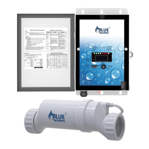
Blueworks BLH Series User manual

1 | P a g e

2 | P a g e
BLUEWORKS BLH Series
SALT CHLORINE GENERATOR
INSTRUCTIONS READ BEFORE USE
There are basic safety precautions that you need to follow to be safe.
Including,
Cautions
Please note, the total working hours for the CELL should be less than 8
hours total per day. If you are using a variable speed pump for 24 hours
a day be sure to adjust the chlorine output to 25-30%. If the pump is
only running 10 hours per day adjust the chlorine output between
60-80%.
You can use this calculation to calculate the appropriate chlorine output
for your pool, suggest at 6 hours per day.
Pump running 24(Hours a day) *25% (Chlorine Output) =6hr (cell run time per day at 25%).
Pump running 20(Hours a day) *30% (Chlorine Output) =6hr (cell run time per day at 30%).
Pump running 15(Hours a day) *40% (Chlorine Output) =6hr (cell run time per day at 40%).
Pump running 12(Hours a day) *50% (Chlorine Output) =6hr (cell run time per day at 50%).
Pump running 8(Hours a day) *75% (Chlorine Output) =6hr (cell run time per day at 75%).
Start the VS pump on a low speed and kick the speed up until the salt
system works.
If your swimming pool has natural stone as a covering or decorative
layer, please consult stone installation experts for stone maintenance
before installing BLH.
When installing and using this electrical equipment, basic safety
precautions should always be exercised, including the following:

3 | P a g e
WARNING
Risk of Electric Shock. All electrical wiring MUST be in conformance
with all applicable local codes, regulations, and the National Electric
Code ® (NEC®).
WARNING
To reduce the risk of injury, do not permit children to use this product.
WARNING
Higher temperatures may require higher chlorine output to maintain
proper free available chlorine residuals. The actual amount of
chlorination required by your pool can change, and varies according
factors not limited to bather load, rain, temperature, dirt, debris, and
chemical balance.
WARNING
Always turn unit off when operating any plumbing control valves such
as for backwashing, water exhaust, or during operation of spa or water
features if operation restricts water flow to the cell. A build-up of
flammable gases will result in hazardous conditions.
When install the machine, ensure that materials and parts used in
the pool are compatible with the use of chlorinated water and salt.
Avoid high salt levels (above the recommended range).
Ensure that the chlorine generator operates only when the
circulation pump is operating. When installed with a pool
equipment timer, the Control Module must be to the load side of
the timer clock.

4 | P a g e
If additional chlorine is required (due to hot weather), use Sodium
Hypochlorite to maintain an appropriate chlorine residual in the
water.
Proper pool chemistry must be maintained at all times.
A green colored terminal is located inside the wiring compartment.
To reduce the risk of electric shock, this terminal must be
connected to the grounding means provided in the electric supply
service panel with a continuous copper wire equivalent in size to
the circuit conductors supplying the equipment.
One bonding for US models is provided on the external surface. To
reduce the risk of electric shock, connect the local common
bonding grid in the area of the swimming pool, spa, or hot tub to
these terminals with an insulated or bare copper conductor not
smaller than 8 AWG US.

5 | P a g e
Table of Contents
OPERATION
Introduction............................................................6
Switches of Control............................................... 7
Water chemistry.....................................................9
Operation ............................................................14
Installation............................................................18
WARRANTY
Warranty..............................................................22
TROUBLESHOOTING
Troubleshooting...................................................27

6 | P a g e
INTRODUCTION
BLH Salt water chlorination is a process that uses dissolved salt for
the chlorination of swimming pools. The chlorine generator
uses electrolysis in the presence of dissolved salt to produce chlorine
gas or its dissolved forms, hypochlorous acid and sodium hypochlorite,
which are already commonly used as sanitizing in pools.
The BLH is designed for residential swimming pool up to 60,000 gallons
(230,000 liters).
The actual amount of chlorination required to properly disinfect the pool
depends on the bather’s load, rainfall, air temperature, water
temperature,exposure of the pool to the sun, pool surface and
cleanliness.

7 | P a g e
Switches of Control
AUTO: Generally, if the BLH is in “Auto”, it will automatically work
according to the chlorine output settings.
SUPER CHLOR: The “Super Chlor” function is the process of
temporarily increasing the free chlorine levels in the pool for the

8 | P a g e
purpose of increased sanitation power. It's often necessary when the
pool water is cloudy, free chlorine levels to fall below optimum
levels. Switch to “ON”. It will work 100%, remember to back to “Auto”
when you have desired chlorine.
OFF: In “OFF” , the BLH stops outputting chlorine.
NOTE: During the maintenance, please turn the power off the
circuit breaker. The OFF switch is not to be used.
OUTPUT LEVEL CONTROL
Adjust this setting to increase or decrease the chlorine output level
percentage.

9 | P a g e
WATER CHEMISTRY
For any pools, it is significant to maintain proper water chemistry of the
pool water, including pH, calcium levels, and alkaline content,
especially to maintain proper levels of salt and stabilizer. It helps to
prevent corrosion or scaling and to bring better experience for pool
users. It is recommended that pool water be professionally tested a
minimum of twice per 3 months and adjust the water chemistry in time.
Remember to tell the pool store service staff that you are using a salt
chlorine generator.
IDEAL CHEMICAL LEVELS
Saturation Index
The “saturation index,” or the “stability index,” is a numerical value
indicating whether or not water is balanced.
Saturation Index = pH + TF + CF + AF – 12.1

10 | P a g e
Ideal Salt Levels & Pool Size
Use the table below to help determine the amount of salt and pool
size.The ideal salt level is between 3000-4000 ppm.

11 | P a g e
Type of Salt to Use
Use evaporated, granular non-iodized salt (sodium chloride). The purer
the salt (at least 99%).
Improve the life and performance of the electrolytic cell. Water softening
salt (also called water conditioner)
Granules are an economical way to buy large amounts of salt. However,
only NaCl salt with a purity of at least 99% can be used. The pill is a
compressed form of evaporated salt and may take longer to dissolve.
Avoid using salt with an anti-caking agent, which may cause
discoloration.
When adding salt to the pool, it’s best to pour the required salt into the
shallow end of the pool and run filter and pump at the same time to
circulate the water and dissolve the salt. Do not pour the salt bag into the
water because the chemicals and ink on the bag will Disturb water
balance. In summer, salt may take 24-48 hours to dissolve, while in
winter it takes longer. Fine grain The salt will dissolve faster than
compressed tablets.
In any swimming pool, do not add salt directly to the skier or directly to
the main drain. Due to the high concentration of salt and reduced pump
flow, this will shut down or shorten the life of the cells.
If the addition is incorrect, please turn off BLH immediately for 24 hours
while the pump and filter are still running. This will help distribute the salt
evenly. The salt display may take up to 24 hours to respond to changes in
salt concentration.

12 | P a g e
Adding Salt
POUNDS and (Kg) OF SALT NEEDED FOR 3400 PPM

13 | P a g e
To ensure BLH working well, swimming pool stabilizer to protect and
extend the life of chlorine generator. Use the chart to see how to reach
ideal 80 ppm.
POUNDS and (Kg) OF STABILIZER (CYANURIC ACID) NEEDED
FOR 80 PPM

14 | P a g e
OPERATION
By familiarizing yourself with the operation of the BLH generator, you
can achieve maximum performance for your pool. When chemical
levels are in the recommended range, there are FOUR factors that you
can control. Filter time each day, amount of salt in the pool, the output
of chlorine you set, and stabilizer level in the water will directly impact
the amount of chlorine the BLH will generate.
When you just begin to set the model, it will take you days to find ideal
chlorine output, you can start at a high setting and then turn down.
Indicators and Diagnostic Displays

15 | P a g e
POWER: Power illuminated, model is in power.
GENERATION: Model in normal operation, the LED will be steady. If it
is flashing, check the pool water chemicals.
SUPER CHLOR: The generator runs at 100% capacity which can
produce enough chlorine to clear up moderate cloudiness, but the
generator is forced to overwork. It will be automatically switched to the
original output after 24- hour SUPER CHLOR operation.
REMOTE: Controlled by remote models (not available)
CHECK CELL: If “Check Cell” LED is flashing and salt level is above
2700ppm, 500hr cell count down timer is active. Once cleaned, hold
down “System Status” button (3-5seconds) to reset timer for 500hrs.
HIGH SALT: When it is on or flashing, BLH is warning that the water
salinity is too high to work.
CHECK SALT: When it is on or flashing, BLH salinity is too low to work.
NO FLOW: When it is on, flow switch detect that there is no flow
through the cell. If it is flashing, the flow is restored.
DIAGNOSTIC DISPLAY
Average Salt Level (default as 2800ppm)
1. Water Temperature (xx degrees Fahrenheit or Celsius)
2. Cell Voltage (20-30VDC)
3. Cell Amperage (How is the cell working,fine or not)
4. Desired Output % (% of cell time ON)
5. Instant salinity
6. Product name sent to the pool automation Control display
(AL0-5=product branding)

16 | P a g e
7. Software revision level
8. Cell type (F-3,F-9,C-9,F-15,C-15,T-15)
BLH20: F-3 BLH30: F-9 BLH40: F-15
9. Salt Calibration (E000)
10. End of the loop (-EE)
Spring Start-up
When reopening the pool after long term, check all water chemistry
before power on the BLH.
Maintenance
When checking other water chemistry levels, always monitor the salinity
level of the swimming pool.
After the system runs for a period of time, it will eventually need to clean
the cells due to the scaling of natural minerals.
You will be notified by opening "CHECK CELL" Light. When lit, cleaning
the cell with a cleaning stand is better.
Important information: The frequency of cleaning depends on your
water chemistry and water saturation index.
For most people, only need to clean a few times per season. Faster
mineral accumulation must be long-term high saturation index,chemical
imbalance may lead to rapid fouling. Consult Swimming pool
professionals.

17 | P a g e
How to clean the cell?
Important information: If there is severe mineral accumulation, more
than one cleaning may be required to dissolve the remaining solids.
After cleaning, carefully inspect the cell plate with bright light. If you see
any remaining scale, debris or physical blocked in the salt cell, please
repeat the cleaning process as needed. If it is "check cell"come back
soon after cleaning,
1) Confirm that the salinity is within the range
2) Ensure that the cell is fully filled with water
3) Verify the cell type setting of the system
Before removing the cell for cleaning or replacement:
1) Turn off all power sources of all swimming pool equipment and close
the water supply line valve (if applicable).
2) Unplug the cell cable connecting to the control box.
3) Loosen the threaded ring around the joint at the junction of the pool
and the pipes.
To clean the cell with mineral deposits:
1) Cleaning stand and adjust the direction of the cell vertically. Place on
the ground and stabilize to keep it upright.
2) In a separate bucket, mix one part of muriatic acid with four parts of
water. Pour this acid solution directly to cell. Make sure that the
cleaning water completely covers the components inside the cell.
3) Wait for the foaming to stop. Let the solution soak for no more than
fifteen minutes.
4) Properly dispose of the acid solution, and use a hose to wash away
the remaining debris from the pool.

18 | P a g e
5) Look inside the unit and check if there is no debris or scale residue. If
necessary, repeat steps 2-4.
6) Re install the cell into the PVC return pipe.
Note: If you do not currently have a cleaning cap or cleaning rack, you
can fully immerse the cell in a five-gallon bucket.
ALWAYS POUR ACID INTO WATER-NEVER POUR WATER INTO ACID.
BE SURE TO WEAR PROTECTIVE GLASSES, CLOTHING, AND CHEMICAL
RESISTANT GLOVES.
INSTALLATION
Before installation, make sure all the water chemistry is in normal
range.
Using 2-inch pipes and should be performed by qualified personnel in
case there is a 1.5-inch pipe, a reducer can be used to fit the system;
be sure to pay attention to any changes.
Check each measurement carefully before cutting.
Mounting the BLH Control
Install the control box as close as possible to the pump and filter system.
For safety reasons, please do not install the control box within 10 feet of
the edge of the pool and comply with all applicable regulations. Verify
cell and flow switch cable can reach the control box.
As with most electronic devices, avoid using the controller above the
heater or in a tightly enclosed or insulated space can avoid excessive
heat accumulation and also avoid being close to acid chemicals, it may
damage the control.
Use screws to fix the mounting bracket of the control box on the wall or

19 | P a g e
vertical bracket comfortably horizontally.
At least 3 feet above the ground. Hang the control on the bracket.
Mounting the Flow Switch, and Cell.
Flow switch, confirm that the arrows on the flow switch (located on the
side) point in the same direction of water flow.
The Cell and Flow Switch cables have easy plug-in connectors in the
control, the diagram below for the location of these connections.

20 | P a g e
Plumbing
These instructions apply to 2-inch pipe (typical). Make sure to choose
with existing pool pipe size (1.5 inches or 2 inches), and discard other
unnecessary joints.
For articulated connections, you will also use the included 2" to 1.5"
reducer bushing to accommodate the flow switch. For 1½"
installations,be sure to pay attention to any new or other measurements
before cutting the tube.
Other manuals for BLH Series
1
Table of contents
Other Blueworks Portable Generator manuals
Popular Portable Generator manuals by other brands
Teknoware
Teknoware TKT66 Installation and maintenance instructions
Wacker Neuson
Wacker Neuson GV 7000A Operator's manual

Briggs & Stratton
Briggs & Stratton 14000 Series installation instructions
Baumer
Baumer GTR 9 Mounting and operating instructions

Champion
Champion 100460 Operator's manual
Wanco
Wanco WSP12 Operator's manual
DANA
DANA Brevini P1510 Series Assembly instructions
Juntek
Juntek JDS2800-60M quick start guide

Lincoln Electric
Lincoln Electric OUTBACK 200 CE Operator's manual
CAMPAGNOLA
CAMPAGNOLA POWER 58 quick guide

Homelite
Homelite HGCA4500 Series quick start guide
Wacker Neuson
Wacker Neuson GP 4000 Operator's manual
