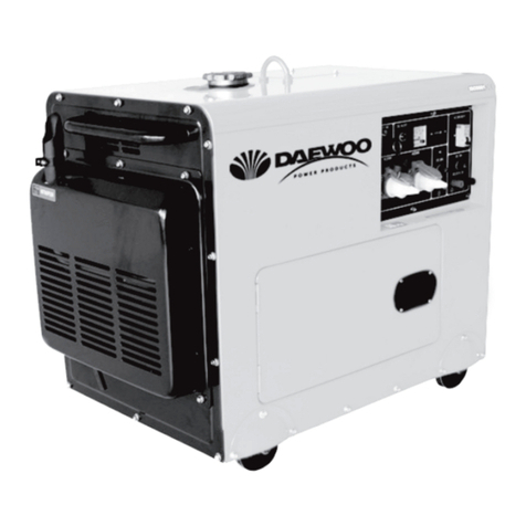
Daewoo DAGFS Series User manual

Manufactured under license of Daewoo International Corporation, Korea
www.daewoopowerproducts.com
USER’S MANUAL
DAGFS-SERIES Silent diesel generator & Digital panel /
Brushless synchronous A.C. Alternators
Blown Air Drying
Remove the covers from all apertures to allow the escape of the water-laden air. During drying,
air must be able to ow freely through the generator in order to carry off the moisture.
Direct hot air from two electrical fan heaters of around 1-3 KW into the generator air inlet aper-
tures. Ensure the heat source is at least 300mm away from the windings to avoid over heating
and damage to the insulation.
Apply the heat and plot the insulation value at half hourly intervals. The process is complete
when the parameters covered in the section entitled, 'Typical Drying Out Curve', are met.
Remove the heaters, replace all covers and re-commission as appropriate.
If the set is not to be run immediately ensure that the anticondensation heaters are energized,
and retest prior to running.
Shirt Circuit Method
NOTE: This process shou ld only be performed by a competent engineer familiar with safe
operating practices within and around generator sets of the type in question. Ensure the gene-
rator is safe to work on, initiate all mechanical and electrical safety procedures pertaining to the
genset and the site.
Bolt a short ci rcuit of adequate current carrying capacity, across the main terminals of the
generator. The shorting link should be capable of taking full load current.
Disconnect the cables from terminals "X" and "XX" of the AVR.
Connect a variable de supply to the "X" (positive) and "XX" (negative) eld cables. The de
supply must be able to provide a current up to 2.0 Amp at 0-24Volts.
Position a suitable ac ammeter to measure the shorting link current.
Set the de supply voltage to zero and start the generating set. Slowly increase the de voltage to
pass current through the exciter eld winding. As the excitation current increases, so the stator
current in the shorting link will increase. This stator output current level must be monitored, and
not allowed to exceed 80% of the generators rated output current.
After every 30 minutes of this exercise: Stop the generator and switch off the separate excita-
tion supply, and measure and record the stator winding IR values, and plot the results.
The resulting graph should be compared with the classic shaped graph. This drying out proce-
dure is complete when the parameters covered in the section entitled 'Typical Drying Out
Curve' are met.
Once the insulation Resistance is raised to an acceptable level minimum value 10MΩ - the de
supply may be removed and the exciter eld leads "X" and "XX" re-connected to their terminals
on the AVR.
Rebuild the genset, replace all covers and re-commission as appropriate.
If the set is not to be run immediately ensure that the anticondensation heaters are energised,
and retest the generator prior to running.
Typical Drying Out Curve
Whichever method is used to dry out the generator the resistance should be measured every
half-hour and a curve plotted as shown.(Fig 9)
The illustration shows a typical curve for a machine that has absorbed a considerable amount
of moisture. The curve indicates a temporary increase in resistance, a fall and then a gradual
rise to a steady state. Point 'A', the steady state, must be greater than 1.0MΩ (If the windings
are only slightly damp the dotted portion of the curve may not appear).
For general guidance expect that the typical time to reach point 'A' will be approximately 3
hours for a LV 6 generator.
Drying should be continued after point "A" has been reached for at least one hour.
It should be noted that as winding temperature increases, values of insulation resistance may
signicantly reduce. Therefore, the reference values for insulation resistance can only be esta-
blished with windings at a temperature of approximately 20°C.
After drying out, the insulation resistances should be rechecked to verify minimum resistances
quoted above are achieved. On re-testing it is recommended that the main stator insulation
resistance is checked as fol lows:
-Separate the neutral leads.
Ground V and W phase and megger U phase to ground
Ground U and W phase and megger V phase to ground
Ground U and V phase and megger W phase to ground.
If the minimum value of 1.0MΩ is not obtained, drying out must be continued and the test
repeated.
If the minimum value of 1.0MΩ for all components cannot be achieved rewinding or refurbish-
ment of the generator will be necessary.
The generator must not be put into service until the minimum value, Of 1.0MΩ for all compo-
nents, can be achieved.
8.2 BEARINGS
All bearings are supplied from the factory pre-packed with Kluber Asonic GHY 72 grease.
Do not mix kluber Asonic GHY 72 with any grease of different specications. Mixing grease of
differing specications will reduce bearing life. The specication for Kluber Asonic FHY 72 is
available on request from the factory.
Sealed for life bearings are tted with integral seals and are not re-greasable.
BEARING LIFE
IMPORTANT! The life of a bearing in service is subject to the working conditions and the
environment.
IMPORTANT! High levels of vibration from the engine or misalignment of the set will
stress the bearing and reduce its service life. If the vibration limits set out
im BS 5000-3 and ISO 8528-9 are exceeded bearing life will be reduced.
Refer to 'vibration’ below.
IMPORTANT! Long stationary periods in an environment where the generator is subject
to vibration can cause false brinneling, which puts ats on the ball and
grooves on the races, leading to premature failure.
IMPORTANT! Very humid atmospheric or wet conditions can emulsify the grease causing
corrosion and deterioration of the grease, leading to premature failure of
the bearings.
HEALTH MONLTORING OF THE BEARINGS
It recommends that the user check the bearing condition, using monitoring equipment, to
determine the state of the bearings. The 'best practice' is to take initial readings as a base line
and periodically monitor the bearings to detect a deteriorating trend. It will then be possible to
plan a bearing change at an appropriate generating set or engine service interval.
VLBRATION
The generators are designed ti withstand the vibration levels encountered on generating sets
built to meet the requirements of ISO 8528-9 and BS5000-3. (Where ISO 8528 is taken to be
broad band measurements and BS5000 refers to the predominant frequency of any vibrations
on the generating set.)
Denition of BSS000-3
Generators shall be capable of continuously withstanding linear vibration levels with amplitudes
of 0.25 mm between 5 Hz and velocities of 9.0 mm/s. Between 8 Hz and 200 Hz when measu-
red at any point directly on the carcass or main frame of the machine. These limits refer Only to
the predominant frequency of v ibration of any complex waveform.
Denition of ISO 8528-9
ISO 8528-9 refers to a broad band of frequencies, the broad band is taken to be between 2
Hertz and 300 Hertz. The table below is an example from ISO 8528-9 (value 1 ). This simplied
table lists the vibration limits by kVA range and speed for acceptable genset operation.
IMPORTANT! Exceeding either o f the above specications will have a detrimental effect
on the life of the bearing. This will invalidate the generator warranty. If you
are in any doubt, contact Newage International limited.
If the vibration levels of the generating set are not within the parameters quoted above.
1. consult the genset builder. The genset builder should address the genset design to reduce
the vibration levels as much ad possible.
2. Discuss the impact of not meeting the above levels on both bearing and generator life
expectancy.
Where requested, or deemed necessary, Newage will work with the genset builder in an
attempt to nd a satisfactory solution.
BEARING 'SERVICELIFE' EXPECTANCY
Bearing manufacturers recognize that the "service life" of their bearings is dependent upon
many factors that are not in their control, they cannot therefore quote a "service life".
Although "service life" cannot be guaranteed, it can be maximized by attention to the genera-
ting set design. An understanding of the genset application will also help the user to maximize
the service life expectancy of the bearings. Particular attention should be paid to the alignment,
reduction of vibration levels, environmental protection, maintenance and monitoring procedu-
res. We does not quote life expectancy gures for bearings, but suggests practicable replace-
ment intervals based on the L 10 life of the bearing, the grease and the recommendations of
the bearing and grease manufacturers. For general-purpose applications, provid ing the vibra-
tion levels do not exceed the levels stated in ISO8528-9* and BS5000-3* and the ambient
temperature does not exceed 50°C the following approximations can be applied when *
(See section on vibration)
Sealed for life Bearings. - Approximately 30,000hours.
Re-greaseable bearings.- Approximately 40,000hours.
This is provided the correct maintenance is carried out, and only Kluber Asonic GHY 72 grease
(or equivalent) is used in all bearings. It is important to note that bearings in service. Under
good operating conditions, can continue to run beyond the remembered re placement period.
It should also be remembered that the r isk of bearing failure increases with time.
8.3 ALR FILTERS
Air lters for the removal of airborne particulate matter (dus) are offered as an addition to the
standard build option. Filters on it's need to be ordered with the generator. Air lters need to
be charged with oil before the genset is put to work (see 8.3.2) The frequency of lter mainte-
nance will depend upon the severity of the site conditions. Regular inspection of the elements
will be required to establish when cleaning is necessary.
Danger! Removal of lter elements enables access to LIVE parts. Only remove elements
with the generator out of service.
8.3.1 CLEANING PROCEDURE
Remove the lter elements from the lter frames. Immerse of ush the element with a suitable
degreasing agent until the element is cleas.
As an alternative procedure a high-pressure water hose with a at nozzle can be used. Sweep
the water spray back and forth across the element from the clean side (ne mesh side of
element) holding the nozzle rm ly against the element surface. Cold water may be adequate
depending upon type of contamination although hot water is preferable.
The element can be inspected for cleanliness by looking through the lter towards the light.
When the roughly clean, no cloudy areas will be seen. Dry elements thoroughly before attemp-
ting to carry out the recharging procedure.
8.3.2 RECHARGING (GHARGING) AIR FILTERS
Charging is best done by totally immersing the dry element into a dip tank containing "Filterko-
te Type k" or commercial lubricating oil SAE 20/50. oils of higher or lower viscosity are not
recommended.
Allow elements to completely drain before retting the elements into the frames and putting
into service.
8.4 FAULT FINDING
IMPORTANT! Before commencing any faultnding procedures, examine all wiring for
broken or loose connections.
Two types of AVR can be tted to the WH generator. The Refer to the generator nameplate for
type of AVR tted.
8.4.1 MX341 AVR, FAULT FINDING
8.5 SEPARATE EXCITATION TEST PROCEDURE
The generator windings, diode assembly and AVR can be checked using the appropriate
following sections.
8.5.1 GENERATOR WINDINGS, ROTATING DIODES and PERMANENT MAGNET GENERA-
TOR (PMG)
IMPORTANT! The resistances quoted apply to a standard winding. For generators
having windings or voltages other than those specied refer to fac-
tory for details. Ensure all disconnected leads are isolated and free
from earth.
IMPORTANT! Incorrect speed setting will give proportional error in voltage out put.
Checking Generator Windings and Rotating Diodes
This procedure is carried out w ith lead X and XX disconnected at the AVR or transformer
control rectier bridge and using a 12 volt d. c. Supply to leads X and XX.
Start the set and run at rated speed.
Measure the voltages at the main output terminals U, V and W. if voltages are balanced and
within +/-10% of the generator nomial voltage, refer to 7 .5.1.1.
Check voltages at AVR terminals 6, 7 and 8. These should be balanced and between 170-250
volts.
If voltages at main terminals are balanced but voltage at 6, 7
and 8 are unbalanced, check continuity of leads 6,7 and 8.
If voltages are unbalanced , refer to 7 .5.1.2.
8.5.1.1 BALANCED MAIN TERMINAL VOLTAGES
If all voltages are balanced within 1 % at the main terminals, it can be assumed that all exciter
windings, main windings and main rotating diodes are in good order ,and the fault is in the
AVR or transformer control. Refer to subsection 7 .3.2 for test procedure.
If voltages are balanced but low, there is a fault in the main excitation windings or rotating
diode assembly. proceed as follows to identity:-
Rectier Diodes
The diodes on the main rectier assembly can be checked with a multimeter. The exible leads
connected to each diode should be disconnected at the terminal end, and the forward and
reverse resistance checked. A healthy diode will indicate a very high resistance ( innity) in the
reverse direction, and a low resistance in the forward direction. A faulty diode will give a full
deection reading in both directions with the test meter on the 10,000 ohms scale, or an
innity reading in both directions. On an electronic digital meter a healthy diode will give a low
res. We does not quote life expectancy gures for bearings, but suggests practicable replace-
ment intervals based on the L 10 life of the bearing, the grease and the recommendations of
the bearing and grease manufacturers. For general-purpose applications, provid ing the vibra-
tion levels do not exceed the levels stated in ISO8528-9* and BS5000-3* and the ambient
temperature does not exceed 50°C the following approximations can be applied when *
(See section on vibration)
Sealed for life Bearings. - Approximately 30,000hours.
Re-greaseable bearings.- Approximately 40,000hours.
This is provided the correct maintenance is carried out, and only Kluber Asonic GHY 72 grease
(or equivalent) is used in all bearings. It is important to note that bearings in service. Under
good operating conditions, can continue to run beyond the remembered re placement period.
It should also be remembered that the r isk of bearing failure increases with time.
8.3 ALR FILTERS
Air lters for the removal of airborne particulate matter (dus) are offered as an addition to the
standard build option. Filters on it's need to be ordered with the generator. Air lters need to
be charged with oil before the genset is put to work (see 8.3.2) The frequency of lter mainte-
nance will depend upon the severity of the site conditions. Regular inspection of the elements
will be required to establish when cleaning is necessary.
Danger! Removal of lter elements enables access to LIVE parts. Only remove elements
with the generator out of service.
8.3.1 CLEANING PROCEDURE
Remove the lter elements from the lter frames. Immerse of ush the element with a suitable
degreasing agent until the element is cleas.
As an alternative procedure a high-pressure water hose with a at nozzle can be used. Sweep
the water spray back and forth across the element from the clean side (ne mesh side of
element) holding the nozzle rm ly against the element surface. Cold water may be adequate
depending upon type of contamination although hot water is preferable.
The element can be inspected for cleanliness by looking through the lter towards the light.
When the roughly clean, no cloudy areas will be seen. Dry elements thoroughly before attemp-
ting to carry out the recharging procedure.

1
1. SAFETY AND WARNING...........................................................................................................................2
2. GENERAL INTRODUCTION.....................................................................................................................6
3. OPERATION INSTRUCTION FOR FIRST START.....................................................................................8
4. MAINTENANCE.......................................................................................................................................14
5. TECHNICAL DATA...................................................................................................................................17
6. DIGITAL PANEL.......................................................................................................................................21
7. EXPLODED VIEW AND PARTS LIST......................................................................................................28
8. EC.............................................................................................................................................................48
9. WARRANTY.............................................................................................................................................49
INDEX
1. SAFETY AND WARNING
The operator of the machine:
Is responsible for and has a duty of care in making sure that the machine is operated safely and
in accordance with the instructions in this user manual.
Should never leave it in a condition, which would allow an untrained or unauthorised person/s
to operate this machine.
Take all due care and diligence for the safety of and with regard to those around whilst using the
machine, to include but not limited to;
Elderly, children, pets, livestock and property.
Some or all of the following PPE, warning signs and symbols may appear throughout this
manual and you must adhere to their warning/s. Failure to do so may result in personal injury.
Personal Protective Equipment (PPE)
Before operation and maintenance for the generator sets, please read carefully about this
manual and make sure a good understanding of this operation manual and other documents
which attached with the engine.
Correct installation of the generator set is the precondition of normal operation. Qualied spare
parts shall be used for maintenance to ensure good running condition and long life expectancy
The generator set shall be operated only by the staffs who have received training on the
operation and the repair shall be made by the authorized staffs. Operator and maintenance staff
shall be clear about safety and preventive actions and operation maintenance procedure.
The generator sets can only be started under safety conditions. Please do not start the
generator sets when any abnormal condition has been found so that to avoid accidents.
When clean, maintain and repair the generator sets, please shut down the generator set and cut
off the connection of negative polar of the battery or dismantle battery connecting cable, and
place warning label at the relative place so that to avoid accident.
The exhaust air discharged from engine is harmful for people’s health. All of the generator sets
installed indoors shall discharge the exhaust gas to outside doors.
During the period of generator set running, the exhaust pipe and silencer will generate high
temperature. Therefore when the generator set is installed, these parts need to be covered with
insulation materials and be kept far away from inammable materials. Please ensure good
ventilation and organized environment for the generator set’s installation room. Please do not
place inammable materials and explosives (liquid) near the engine.
Smoking, spark over, and other re lighting behaviors are not allowed in the area which is close
to the battery and fuel because the mixture of volatilization from fuel and hydrogen generated by
battery charging process will cause explosion when it meets sparkle or naked ame.
The generator set installation room shall be facilitated with BC and ABC re extinguisher, and
operators shall be familiar with the knowledge on how to use it.
When fan protection cover or other protection cover has been detached, please do not try to
start the generator set; and when the generator set has to be started, please don’t put your hand
in the area where the protection cover is missing or make repair around these areas. please keep
your palm, arm, long hair, jewelry and loose clothes far away from belt pulley, belt and other
power transmission parts.
When working in the generator set installation room, please ware working clothes, gloves and
hat. After the generator set being started, please don’t try to open the cover of the radiator
before the anti‐freeze fully cooled down, so that to avoid steam (hot water) burst forth to hurt
people. Please don’t swallow or let your skin contact with the harmful materials such as fuel,
anti‐freeze, lubricant and electrolyte.
When you skin is spattered with these kinds of liquids, please use plenty of water to rinse.
Long time stay in high noise level environment will cause harm to your hearing. If you have to
work around the generator set frequently, you’d better ware the device to protect your ear.
When the generator set need to make cable connections to output power, the operation shall
conform to the condition, specication, standard related to power distribution. Qualied cable
shall be used to make power distribution.
When the installation of generator set involves with welding, please do not connect to the
ground circuit or make grounding through generator set (engine) so that to avoid the big current
generated from welding operation hurt the electric appliance, bearing and bearing bush etc.
inside of the generator set. Please ensure the safety of generator set and reliable grounding.
SAFETY LABELS INFORMATION
TRANSPORT WARNING
• Never lift the generating set by attaching to the engine
or alternator lifting lugs, instead use the lifting points on the
base frame or canopy.
• Ensure that the lifting rigging and supporting structure is
in good condition and has a capacity suitable for the load.
• Keep all personnel away from the generating set when it
is suspended.
MECHANICAL WARNING
• Do not attempt to operate the generating set with the
safety guards removed. While the generating set is run
ning do not attempt to reach under or around the guards
to do maintenance or for any other reason.
• Keep hands, arms, long hair, loose clothing and jewel
ers away from pulleys, belts and other moving parts.
SAFEGUARD WARNING
• Generating sets that are not equipped with sound att
enuating enclosures can produce noise levels in excess
of 105 dB (A). Prolonged exposure to noise levels above
85 dB (A) is hazardous to hearing.
• Wear protective clothing including gloves and hat whe
n working around the generating set.
• If equipped keep access doors on enclosures closed and locke
d when not required to be open.
• Avoid contact with hot oil, hot coolant, hot exhaust gases, hot
surfaces and sharp edges and corners.
Blown Air Drying
Remove the covers from all apertures to allow the escape of the water-laden air. During drying,
air must be able to ow freely through the generator in order to carry off the moisture.
Direct hot air from two electrical fan heaters of around 1-3 KW into the generator air inlet aper-
tures. Ensure the heat source is at least 300mm away from the windings to avoid over heating
and damage to the insulation.
Apply the heat and plot the insulation value at half hourly intervals. The process is complete
when the parameters covered in the section entitled, 'Typical Drying Out Curve', are met.
Remove the heaters, replace all covers and re-commission as appropriate.
If the set is not to be run immediately ensure that the anticondensation heaters are energized,
and retest prior to running.
Shirt Circuit Method
NOTE: This process shou ld only be performed by a competent engineer familiar with safe
operating practices within and around generator sets of the type in question. Ensure the gene-
rator is safe to work on, initiate all mechanical and electrical safety procedures pertaining to the
genset and the site.
Bolt a short ci rcuit of adequate current carrying capacity, across the main terminals of the
generator. The shorting link should be capable of taking full load current.
Disconnect the cables from terminals "X" and "XX" of the AVR.
Connect a variable de supply to the "X" (positive) and "XX" (negative) eld cables. The de
supply must be able to provide a current up to 2.0 Amp at 0-24Volts.
Position a suitable ac ammeter to measure the shorting link current.
Set the de supply voltage to zero and start the generating set. Slowly increase the de voltage to
pass current through the exciter eld winding. As the excitation current increases, so the stator
current in the shorting link will increase. This stator output current level must be monitored, and
not allowed to exceed 80% of the generators rated output current.
After every 30 minutes of this exercise: Stop the generator and switch off the separate excita-
tion supply, and measure and record the stator winding IR values, and plot the results.
The resulting graph should be compared with the classic shaped graph. This drying out proce-
dure is complete when the parameters covered in the section entitled 'Typical Drying Out
Curve' are met.
Once the insulation Resistance is raised to an acceptable level minimum value 10MΩ - the de
supply may be removed and the exciter eld leads "X" and "XX" re-connected to their terminals
on the AVR.
Rebuild the genset, replace all covers and re-commission as appropriate.
If the set is not to be run immediately ensure that the anticondensation heaters are energised,
and retest the generator prior to running.
Typical Drying Out Curve
Whichever method is used to dry out the generator the resistance should be measured every
half-hour and a curve plotted as shown.(Fig 9)
The illustration shows a typical curve for a machine that has absorbed a considerable amount
of moisture. The curve indicates a temporary increase in resistance, a fall and then a gradual
rise to a steady state. Point 'A', the steady state, must be greater than 1.0MΩ (If the windings
are only slightly damp the dotted portion of the curve may not appear).
For general guidance expect that the typical time to reach point 'A' will be approximately 3
hours for a LV 6 generator.
Drying should be continued after point "A" has been reached for at least one hour.
It should be noted that as winding temperature increases, values of insulation resistance may
signicantly reduce. Therefore, the reference values for insulation resistance can only be esta-
blished with windings at a temperature of approximately 20°C.
After drying out, the insulation resistances should be rechecked to verify minimum resistances
quoted above are achieved. On re-testing it is recommended that the main stator insulation
resistance is checked as fol lows:
-Separate the neutral leads.
Ground V and W phase and megger U phase to ground
Ground U and W phase and megger V phase to ground
Ground U and V phase and megger W phase to ground.
If the minimum value of 1.0MΩ is not obtained, drying out must be continued and the test
repeated.
If the minimum value of 1.0MΩ for all components cannot be achieved rewinding or refurbish-
ment of the generator will be necessary.
The generator must not be put into service until the minimum value, Of 1.0MΩ for all compo-
nents, can be achieved.
8.2 BEARINGS
All bearings are supplied from the factory pre-packed with Kluber Asonic GHY 72 grease.
Do not mix kluber Asonic GHY 72 with any grease of different specications. Mixing grease of
differing specications will reduce bearing life. The specication for Kluber Asonic FHY 72 is
available on request from the factory.
Sealed for life bearings are tted with integral seals and are not re-greasable.
BEARING LIFE
IMPORTANT! The life of a bearing in service is subject to the working conditions and the
environment.
IMPORTANT! High levels of vibration from the engine or misalignment of the set will
stress the bearing and reduce its service life. If the vibration limits set out
im BS 5000-3 and ISO 8528-9 are exceeded bearing life will be reduced.
Refer to 'vibration’ below.
IMPORTANT! Long stationary periods in an environment where the generator is subject
to vibration can cause false brinneling, which puts ats on the ball and
grooves on the races, leading to premature failure.
IMPORTANT! Very humid atmospheric or wet conditions can emulsify the grease causing
corrosion and deterioration of the grease, leading to premature failure of
the bearings.
HEALTH MONLTORING OF THE BEARINGS
It recommends that the user check the bearing condition, using monitoring equipment, to
determine the state of the bearings. The 'best practice' is to take initial readings as a base line
and periodically monitor the bearings to detect a deteriorating trend. It will then be possible to
plan a bearing change at an appropriate generating set or engine service interval.
VLBRATION
The generators are designed ti withstand the vibration levels encountered on generating sets
built to meet the requirements of ISO 8528-9 and BS5000-3. (Where ISO 8528 is taken to be
broad band measurements and BS5000 refers to the predominant frequency of any vibrations
on the generating set.)
Denition of BSS000-3
Generators shall be capable of continuously withstanding linear vibration levels with amplitudes
of 0.25 mm between 5 Hz and velocities of 9.0 mm/s. Between 8 Hz and 200 Hz when measu-
red at any point directly on the carcass or main frame of the machine. These limits refer Only to
the predominant frequency of v ibration of any complex waveform.
Denition of ISO 8528-9
ISO 8528-9 refers to a broad band of frequencies, the broad band is taken to be between 2
Hertz and 300 Hertz. The table below is an example from ISO 8528-9 (value 1 ). This simplied
table lists the vibration limits by kVA range and speed for acceptable genset operation.
IMPORTANT! Exceeding either o f the above specications will have a detrimental effect
on the life of the bearing. This will invalidate the generator warranty. If you
are in any doubt, contact Newage International limited.
If the vibration levels of the generating set are not within the parameters quoted above.
1. consult the genset builder. The genset builder should address the genset design to reduce
the vibration levels as much ad possible.
2. Discuss the impact of not meeting the above levels on both bearing and generator life
expectancy.
Where requested, or deemed necessary, Newage will work with the genset builder in an
attempt to nd a satisfactory solution.
BEARING 'SERVICELIFE' EXPECTANCY
Bearing manufacturers recognize that the "service life" of their bearings is dependent upon
many factors that are not in their control, they cannot therefore quote a "service life".
Although "service life" cannot be guaranteed, it can be maximized by attention to the genera-
ting set design. An understanding of the genset application will also help the user to maximize
the service life expectancy of the bearings. Particular attention should be paid to the alignment,
reduction of vibration levels, environmental protection, maintenance and monitoring procedu-
res. We does not quote life expectancy gures for bearings, but suggests practicable replace-
ment intervals based on the L 10 life of the bearing, the grease and the recommendations of
the bearing and grease manufacturers. For general-purpose applications, provid ing the vibra-
tion levels do not exceed the levels stated in ISO8528-9* and BS5000-3* and the ambient
temperature does not exceed 50°C the following approximations can be applied when *
(See section on vibration)
Sealed for life Bearings. - Approximately 30,000hours.
Re-greaseable bearings.- Approximately 40,000hours.
This is provided the correct maintenance is carried out, and only Kluber Asonic GHY 72 grease
(or equivalent) is used in all bearings. It is important to note that bearings in service. Under
good operating conditions, can continue to run beyond the remembered re placement period.
It should also be remembered that the r isk of bearing failure increases with time.
8.3 ALR FILTERS
Air lters for the removal of airborne particulate matter (dus) are offered as an addition to the
standard build option. Filters on it's need to be ordered with the generator. Air lters need to
be charged with oil before the genset is put to work (see 8.3.2) The frequency of lter mainte-
nance will depend upon the severity of the site conditions. Regular inspection of the elements
will be required to establish when cleaning is necessary.
Danger! Removal of lter elements enables access to LIVE parts. Only remove elements
with the generator out of service.
8.3.1 CLEANING PROCEDURE
Remove the lter elements from the lter frames. Immerse of ush the element with a suitable
degreasing agent until the element is cleas.
As an alternative procedure a high-pressure water hose with a at nozzle can be used. Sweep
the water spray back and forth across the element from the clean side (ne mesh side of
element) holding the nozzle rm ly against the element surface. Cold water may be adequate
depending upon type of contamination although hot water is preferable.
The element can be inspected for cleanliness by looking through the lter towards the light.
When the roughly clean, no cloudy areas will be seen. Dry elements thoroughly before attemp-
ting to carry out the recharging procedure.
8.3.2 RECHARGING (GHARGING) AIR FILTERS
Charging is best done by totally immersing the dry element into a dip tank containing "Filterko-
te Type k" or commercial lubricating oil SAE 20/50. oils of higher or lower viscosity are not
recommended.
Allow elements to completely drain before retting the elements into the frames and putting
into service.
8.4 FAULT FINDING
IMPORTANT! Before commencing any faultnding procedures, examine all wiring for
broken or loose connections.
Two types of AVR can be tted to the WH generator. The Refer to the generator nameplate for
type of AVR tted.
8.4.1 MX341 AVR, FAULT FINDING
8.5 SEPARATE EXCITATION TEST PROCEDURE
The generator windings, diode assembly and AVR can be checked using the appropriate
following sections.
8.5.1 GENERATOR WINDINGS, ROTATING DIODES and PERMANENT MAGNET GENERA-
TOR (PMG)
IMPORTANT! The resistances quoted apply to a standard winding. For generators
having windings or voltages other than those specied refer to fac-
tory for details. Ensure all disconnected leads are isolated and free
from earth.
IMPORTANT! Incorrect speed setting will give proportional error in voltage out put.
Checking Generator Windings and Rotating Diodes
This procedure is carried out w ith lead X and XX disconnected at the AVR or transformer
control rectier bridge and using a 12 volt d. c. Supply to leads X and XX.
Start the set and run at rated speed.
Measure the voltages at the main output terminals U, V and W. if voltages are balanced and
within +/-10% of the generator nomial voltage, refer to 7 .5.1.1.
Check voltages at AVR terminals 6, 7 and 8. These should be balanced and between 170-250
volts.
If voltages at main terminals are balanced but voltage at 6, 7
and 8 are unbalanced, check continuity of leads 6,7 and 8.
If voltages are unbalanced , refer to 7 .5.1.2.
8.5.1.1 BALANCED MAIN TERMINAL VOLTAGES
If all voltages are balanced within 1 % at the main terminals, it can be assumed that all exciter
windings, main windings and main rotating diodes are in good order ,and the fault is in the
AVR or transformer control. Refer to subsection 7 .3.2 for test procedure.
If voltages are balanced but low, there is a fault in the main excitation windings or rotating
diode assembly. proceed as follows to identity:-
Rectier Diodes
The diodes on the main rectier assembly can be checked with a multimeter. The exible leads
connected to each diode should be disconnected at the terminal end, and the forward and
reverse resistance checked. A healthy diode will indicate a very high resistance ( innity) in the
reverse direction, and a low resistance in the forward direction. A faulty diode will give a full
deection reading in both directions with the test meter on the 10,000 ohms scale, or an
innity reading in both directions. On an electronic digital meter a healthy diode will give a low

2
1. SAFETY AND WARNING
The operator of the machine:
Is responsible for and has a duty of care in making sure that the machine is operated safely and
in accordance with the instructions in this user manual.
Should never leave it in a condition, which would allow an untrained or unauthorised person/s
to operate this machine.
Take all due care and diligence for the safety of and with regard to those around whilst using the
machine, to include but not limited to;
Elderly, children, pets, livestock and property.
Some or all of the following PPE, warning signs and symbols may appear throughout this
manual and you must adhere to their warning/s. Failure to do so may result in personal injury.
Personal Protective Equipment (PPE)
Before operation and maintenance for the generator sets, please read carefully about this
manual and make sure a good understanding of this operation manual and other documents
which attached with the engine.
Correct installation of the generator set is the precondition of normal operation. Qualied spare
parts shall be used for maintenance to ensure good running condition and long life expectancy
The generator set shall be operated only by the staffs who have received training on the
operation and the repair shall be made by the authorized staffs. Operator and maintenance staff
shall be clear about safety and preventive actions and operation maintenance procedure.
The generator sets can only be started under safety conditions. Please do not start the
generator sets when any abnormal condition has been found so that to avoid accidents.
When clean, maintain and repair the generator sets, please shut down the generator set and cut
off the connection of negative polar of the battery or dismantle battery connecting cable, and
place warning label at the relative place so that to avoid accident.
The exhaust air discharged from engine is harmful for people’s health. All of the generator sets
installed indoors shall discharge the exhaust gas to outside doors.
During the period of generator set running, the exhaust pipe and silencer will generate high
temperature. Therefore when the generator set is installed, these parts need to be covered with
insulation materials and be kept far away from inammable materials. Please ensure good
ventilation and organized environment for the generator set’s installation room. Please do not
place inammable materials and explosives (liquid) near the engine.
Smoking, spark over, and other re lighting behaviors are not allowed in the area which is close
to the battery and fuel because the mixture of volatilization from fuel and hydrogen generated by
battery charging process will cause explosion when it meets sparkle or naked ame.
The generator set installation room shall be facilitated with BC and ABC re extinguisher, and
operators shall be familiar with the knowledge on how to use it.
When fan protection cover or other protection cover has been detached, please do not try to
start the generator set; and when the generator set has to be started, please don’t put your hand
in the area where the protection cover is missing or make repair around these areas. please keep
your palm, arm, long hair, jewelry and loose clothes far away from belt pulley, belt and other
power transmission parts.
When working in the generator set installation room, please ware working clothes, gloves and
hat. After the generator set being started, please don’t try to open the cover of the radiator
before the anti‐freeze fully cooled down, so that to avoid steam (hot water) burst forth to hurt
people. Please don’t swallow or let your skin contact with the harmful materials such as fuel,
anti‐freeze, lubricant and electrolyte.
When you skin is spattered with these kinds of liquids, please use plenty of water to rinse.
Long time stay in high noise level environment will cause harm to your hearing. If you have to
work around the generator set frequently, you’d better ware the device to protect your ear.
When the generator set need to make cable connections to output power, the operation shall
conform to the condition, specication, standard related to power distribution. Qualied cable
shall be used to make power distribution.
When the installation of generator set involves with welding, please do not connect to the
ground circuit or make grounding through generator set (engine) so that to avoid the big current
generated from welding operation hurt the electric appliance, bearing and bearing bush etc.
inside of the generator set. Please ensure the safety of generator set and reliable grounding.
SAFETY LABELS INFORMATION
TRANSPORT WARNING
• Never lift the generating set by attaching to the engine
or alternator lifting lugs, instead use the lifting points on the
base frame or canopy.
• Ensure that the lifting rigging and supporting structure is
in good condition and has a capacity suitable for the load.
• Keep all personnel away from the generating set when it
is suspended.
MECHANICAL WARNING
• Do not attempt to operate the generating set with the
safety guards removed. While the generating set is run
ning do not attempt to reach under or around the guards
to do maintenance or for any other reason.
• Keep hands, arms, long hair, loose clothing and jewel
ers away from pulleys, belts and other moving parts.
SAFEGUARD WARNING
• Generating sets that are not equipped with sound att
enuating enclosures can produce noise levels in excess
of 105 dB (A). Prolonged exposure to noise levels above
85 dB (A) is hazardous to hearing.
• Wear protective clothing including gloves and hat whe
n working around the generating set.
• If equipped keep access doors on enclosures closed and locke
d when not required to be open.
• Avoid contact with hot oil, hot coolant, hot exhaust gases, hot
surfaces and sharp edges and corners.
Blown Air Drying
Remove the covers from all apertures to allow the escape of the water-laden air. During drying,
air must be able to ow freely through the generator in order to carry off the moisture.
Direct hot air from two electrical fan heaters of around 1-3 KW into the generator air inlet aper-
tures. Ensure the heat source is at least 300mm away from the windings to avoid over heating
and damage to the insulation.
Apply the heat and plot the insulation value at half hourly intervals. The process is complete
when the parameters covered in the section entitled, 'Typical Drying Out Curve', are met.
Remove the heaters, replace all covers and re-commission as appropriate.
If the set is not to be run immediately ensure that the anticondensation heaters are energized,
and retest prior to running.
Shirt Circuit Method
NOTE: This process shou ld only be performed by a competent engineer familiar with safe
operating practices within and around generator sets of the type in question. Ensure the gene-
rator is safe to work on, initiate all mechanical and electrical safety procedures pertaining to the
genset and the site.
Bolt a short ci rcuit of adequate current carrying capacity, across the main terminals of the
generator. The shorting link should be capable of taking full load current.
Disconnect the cables from terminals "X" and "XX" of the AVR.
Connect a variable de supply to the "X" (positive) and "XX" (negative) eld cables. The de
supply must be able to provide a current up to 2.0 Amp at 0-24Volts.
Position a suitable ac ammeter to measure the shorting link current.
Set the de supply voltage to zero and start the generating set. Slowly increase the de voltage to
pass current through the exciter eld winding. As the excitation current increases, so the stator
current in the shorting link will increase. This stator output current level must be monitored, and
not allowed to exceed 80% of the generators rated output current.
After every 30 minutes of this exercise: Stop the generator and switch off the separate excita-
tion supply, and measure and record the stator winding IR values, and plot the results.
The resulting graph should be compared with the classic shaped graph. This drying out proce-
dure is complete when the parameters covered in the section entitled 'Typical Drying Out
Curve' are met.
Once the insulation Resistance is raised to an acceptable level minimum value 10MΩ - the de
supply may be removed and the exciter eld leads "X" and "XX" re-connected to their terminals
on the AVR.
Rebuild the genset, replace all covers and re-commission as appropriate.
If the set is not to be run immediately ensure that the anticondensation heaters are energised,
and retest the generator prior to running.
Typical Drying Out Curve
Whichever method is used to dry out the generator the resistance should be measured every
half-hour and a curve plotted as shown.(Fig 9)
The illustration shows a typical curve for a machine that has absorbed a considerable amount
of moisture. The curve indicates a temporary increase in resistance, a fall and then a gradual
rise to a steady state. Point 'A', the steady state, must be greater than 1.0MΩ (If the windings
are only slightly damp the dotted portion of the curve may not appear).
For general guidance expect that the typical time to reach point 'A' will be approximately 3
hours for a LV 6 generator.
Drying should be continued after point "A" has been reached for at least one hour.
It should be noted that as winding temperature increases, values of insulation resistance may
signicantly reduce. Therefore, the reference values for insulation resistance can only be esta-
blished with windings at a temperature of approximately 20°C.
After drying out, the insulation resistances should be rechecked to verify minimum resistances
quoted above are achieved. On re-testing it is recommended that the main stator insulation
resistance is checked as fol lows:
-Separate the neutral leads.
Ground V and W phase and megger U phase to ground
Ground U and W phase and megger V phase to ground
Ground U and V phase and megger W phase to ground.
If the minimum value of 1.0MΩ is not obtained, drying out must be continued and the test
repeated.
If the minimum value of 1.0MΩ for all components cannot be achieved rewinding or refurbish-
ment of the generator will be necessary.
The generator must not be put into service until the minimum value, Of 1.0MΩ for all compo-
nents, can be achieved.
8.2 BEARINGS
All bearings are supplied from the factory pre-packed with Kluber Asonic GHY 72 grease.
Do not mix kluber Asonic GHY 72 with any grease of different specications. Mixing grease of
differing specications will reduce bearing life. The specication for Kluber Asonic FHY 72 is
available on request from the factory.
Sealed for life bearings are tted with integral seals and are not re-greasable.
BEARING LIFE
IMPORTANT! The life of a bearing in service is subject to the working conditions and the
environment.
IMPORTANT! High levels of vibration from the engine or misalignment of the set will
stress the bearing and reduce its service life. If the vibration limits set out
im BS 5000-3 and ISO 8528-9 are exceeded bearing life will be reduced.
Refer to 'vibration’ below.
IMPORTANT! Long stationary periods in an environment where the generator is subject
to vibration can cause false brinneling, which puts ats on the ball and
grooves on the races, leading to premature failure.
IMPORTANT! Very humid atmospheric or wet conditions can emulsify the grease causing
corrosion and deterioration of the grease, leading to premature failure of
the bearings.
HEALTH MONLTORING OF THE BEARINGS
It recommends that the user check the bearing condition, using monitoring equipment, to
determine the state of the bearings. The 'best practice' is to take initial readings as a base line
and periodically monitor the bearings to detect a deteriorating trend. It will then be possible to
plan a bearing change at an appropriate generating set or engine service interval.
VLBRATION
The generators are designed ti withstand the vibration levels encountered on generating sets
built to meet the requirements of ISO 8528-9 and BS5000-3. (Where ISO 8528 is taken to be
broad band measurements and BS5000 refers to the predominant frequency of any vibrations
on the generating set.)
Denition of BSS000-3
Generators shall be capable of continuously withstanding linear vibration levels with amplitudes
of 0.25 mm between 5 Hz and velocities of 9.0 mm/s. Between 8 Hz and 200 Hz when measu-
red at any point directly on the carcass or main frame of the machine. These limits refer Only to
the predominant frequency of v ibration of any complex waveform.
Denition of ISO 8528-9
ISO 8528-9 refers to a broad band of frequencies, the broad band is taken to be between 2
Hertz and 300 Hertz. The table below is an example from ISO 8528-9 (value 1 ). This simplied
table lists the vibration limits by kVA range and speed for acceptable genset operation.
IMPORTANT! Exceeding either o f the above specications will have a detrimental effect
on the life of the bearing. This will invalidate the generator warranty. If you
are in any doubt, contact Newage International limited.
If the vibration levels of the generating set are not within the parameters quoted above.
1. consult the genset builder. The genset builder should address the genset design to reduce
the vibration levels as much ad possible.
2. Discuss the impact of not meeting the above levels on both bearing and generator life
expectancy.
Where requested, or deemed necessary, Newage will work with the genset builder in an
attempt to nd a satisfactory solution.
BEARING 'SERVICELIFE' EXPECTANCY
Bearing manufacturers recognize that the "service life" of their bearings is dependent upon
many factors that are not in their control, they cannot therefore quote a "service life".
Although "service life" cannot be guaranteed, it can be maximized by attention to the genera-
ting set design. An understanding of the genset application will also help the user to maximize
the service life expectancy of the bearings. Particular attention should be paid to the alignment,
reduction of vibration levels, environmental protection, maintenance and monitoring procedu-
res. We does not quote life expectancy gures for bearings, but suggests practicable replace-
ment intervals based on the L 10 life of the bearing, the grease and the recommendations of
the bearing and grease manufacturers. For general-purpose applications, provid ing the vibra-
tion levels do not exceed the levels stated in ISO8528-9* and BS5000-3* and the ambient
temperature does not exceed 50°C the following approximations can be applied when *
(See section on vibration)
Sealed for life Bearings. - Approximately 30,000hours.
Re-greaseable bearings.- Approximately 40,000hours.
This is provided the correct maintenance is carried out, and only Kluber Asonic GHY 72 grease
(or equivalent) is used in all bearings. It is important to note that bearings in service. Under
good operating conditions, can continue to run beyond the remembered re placement period.
It should also be remembered that the r isk of bearing failure increases with time.
8.3 ALR FILTERS
Air lters for the removal of airborne particulate matter (dus) are offered as an addition to the
standard build option. Filters on it's need to be ordered with the generator. Air lters need to
be charged with oil before the genset is put to work (see 8.3.2) The frequency of lter mainte-
nance will depend upon the severity of the site conditions. Regular inspection of the elements
will be required to establish when cleaning is necessary.
Danger! Removal of lter elements enables access to LIVE parts. Only remove elements
with the generator out of service.
8.3.1 CLEANING PROCEDURE
Remove the lter elements from the lter frames. Immerse of ush the element with a suitable
degreasing agent until the element is cleas.
As an alternative procedure a high-pressure water hose with a at nozzle can be used. Sweep
the water spray back and forth across the element from the clean side (ne mesh side of
element) holding the nozzle rm ly against the element surface. Cold water may be adequate
depending upon type of contamination although hot water is preferable.
The element can be inspected for cleanliness by looking through the lter towards the light.
When the roughly clean, no cloudy areas will be seen. Dry elements thoroughly before attemp-
ting to carry out the recharging procedure.
8.3.2 RECHARGING (GHARGING) AIR FILTERS
Charging is best done by totally immersing the dry element into a dip tank containing "Filterko-
te Type k" or commercial lubricating oil SAE 20/50. oils of higher or lower viscosity are not
recommended.
Allow elements to completely drain before retting the elements into the frames and putting
into service.
8.4 FAULT FINDING
IMPORTANT! Before commencing any faultnding procedures, examine all wiring for
broken or loose connections.
Two types of AVR can be tted to the WH generator. The Refer to the generator nameplate for
type of AVR tted.
8.4.1 MX341 AVR, FAULT FINDING
8.5 SEPARATE EXCITATION TEST PROCEDURE
The generator windings, diode assembly and AVR can be checked using the appropriate
following sections.
8.5.1 GENERATOR WINDINGS, ROTATING DIODES and PERMANENT MAGNET GENERA-
TOR (PMG)
IMPORTANT! The resistances quoted apply to a standard winding. For generators
having windings or voltages other than those specied refer to fac-
tory for details. Ensure all disconnected leads are isolated and free
from earth.
IMPORTANT! Incorrect speed setting will give proportional error in voltage out put.
Checking Generator Windings and Rotating Diodes
This procedure is carried out w ith lead X and XX disconnected at the AVR or transformer
control rectier bridge and using a 12 volt d. c. Supply to leads X and XX.
Start the set and run at rated speed.
Measure the voltages at the main output terminals U, V and W. if voltages are balanced and
within +/-10% of the generator nomial voltage, refer to 7 .5.1.1.
Check voltages at AVR terminals 6, 7 and 8. These should be balanced and between 170-250
volts.
If voltages at main terminals are balanced but voltage at 6, 7
and 8 are unbalanced, check continuity of leads 6,7 and 8.
If voltages are unbalanced , refer to 7 .5.1.2.
8.5.1.1 BALANCED MAIN TERMINAL VOLTAGES
If all voltages are balanced within 1 % at the main terminals, it can be assumed that all exciter
windings, main windings and main rotating diodes are in good order ,and the fault is in the
AVR or transformer control. Refer to subsection 7 .3.2 for test procedure.
If voltages are balanced but low, there is a fault in the main excitation windings or rotating
diode assembly. proceed as follows to identity:-
Rectier Diodes
The diodes on the main rectier assembly can be checked with a multimeter. The exible leads
connected to each diode should be disconnected at the terminal end, and the forward and
reverse resistance checked. A healthy diode will indicate a very high resistance ( innity) in the
reverse direction, and a low resistance in the forward direction. A faulty diode will give a full
deection reading in both directions with the test meter on the 10,000 ohms scale, or an
innity reading in both directions. On an electronic digital meter a healthy diode will give a low
3
1. SAFETY AND WARNING
The operator of the machine:
Is responsible for and has a duty of care in making sure that the machine is operated safely and
in accordance with the instructions in this user manual.
Should never leave it in a condition, which would allow an untrained or unauthorised person/s
to operate this machine.
Take all due care and diligence for the safety of and with regard to those around whilst using the
machine, to include but not limited to;
Elderly, children, pets, livestock and property.
Some or all of the following PPE, warning signs and symbols may appear throughout this
manual and you must adhere to their warning/s. Failure to do so may result in personal injury.
Personal Protective Equipment (PPE)
Before operation and maintenance for the generator sets, please read carefully about this
manual and make sure a good understanding of this operation manual and other documents
which attached with the engine.
Correct installation of the generator set is the precondition of normal operation. Qualied spare
parts shall be used for maintenance to ensure good running condition and long life expectancy
The generator set shall be operated only by the staffs who have received training on the
operation and the repair shall be made by the authorized staffs. Operator and maintenance staff
shall be clear about safety and preventive actions and operation maintenance procedure.
The generator sets can only be started under safety conditions. Please do not start the
generator sets when any abnormal condition has been found so that to avoid accidents.
When clean, maintain and repair the generator sets, please shut down the generator set and cut
off the connection of negative polar of the battery or dismantle battery connecting cable, and
place warning label at the relative place so that to avoid accident.
The exhaust air discharged from engine is harmful for people’s health. All of the generator sets
installed indoors shall discharge the exhaust gas to outside doors.
During the period of generator set running, the exhaust pipe and silencer will generate high
temperature. Therefore when the generator set is installed, these parts need to be covered with
insulation materials and be kept far away from inammable materials. Please ensure good
ventilation and organized environment for the generator set’s installation room. Please do not
place inammable materials and explosives (liquid) near the engine.
Smoking, spark over, and other re lighting behaviors are not allowed in the area which is close
to the battery and fuel because the mixture of volatilization from fuel and hydrogen generated by
battery charging process will cause explosion when it meets sparkle or naked ame.
The generator set installation room shall be facilitated with BC and ABC re extinguisher, and
operators shall be familiar with the knowledge on how to use it.
When fan protection cover or other protection cover has been detached, please do not try to
start the generator set; and when the generator set has to be started, please don’t put your hand
in the area where the protection cover is missing or make repair around these areas. please keep
your palm, arm, long hair, jewelry and loose clothes far away from belt pulley, belt and other
power transmission parts.
When working in the generator set installation room, please ware working clothes, gloves and
hat. After the generator set being started, please don’t try to open the cover of the radiator
before the anti‐freeze fully cooled down, so that to avoid steam (hot water) burst forth to hurt
people. Please don’t swallow or let your skin contact with the harmful materials such as fuel,
anti‐freeze, lubricant and electrolyte.
When you skin is spattered with these kinds of liquids, please use plenty of water to rinse.
Long time stay in high noise level environment will cause harm to your hearing. If you have to
work around the generator set frequently, you’d better ware the device to protect your ear.
When the generator set need to make cable connections to output power, the operation shall
conform to the condition, specication, standard related to power distribution. Qualied cable
shall be used to make power distribution.
When the installation of generator set involves with welding, please do not connect to the
ground circuit or make grounding through generator set (engine) so that to avoid the big current
generated from welding operation hurt the electric appliance, bearing and bearing bush etc.
inside of the generator set. Please ensure the safety of generator set and reliable grounding.
SAFETY LABELS INFORMATION
TRANSPORT WARNING
• Never lift the generating set by attaching to the engine
or alternator lifting lugs, instead use the lifting points on the
base frame or canopy.
• Ensure that the lifting rigging and supporting structure is
in good condition and has a capacity suitable for the load.
• Keep all personnel away from the generating set when it
is suspended.
MECHANICAL WARNING
• Do not attempt to operate the generating set with the
safety guards removed. While the generating set is run
ning do not attempt to reach under or around the guards
to do maintenance or for any other reason.
• Keep hands, arms, long hair, loose clothing and jewel
ers away from pulleys, belts and other moving parts.
SAFEGUARD WARNING
• Generating sets that are not equipped with sound att
enuating enclosures can produce noise levels in excess
of 105 dB (A). Prolonged exposure to noise levels above
85 dB (A) is hazardous to hearing.
• Wear protective clothing including gloves and hat whe
n working around the generating set.
• If equipped keep access doors on enclosures closed and locke
d when not required to be open.
• Avoid contact with hot oil, hot coolant, hot exhaust gases, hot
surfaces and sharp edges and corners.
Blown Air Drying
Remove the covers from all apertures to allow the escape of the water-laden air. During drying,
air must be able to ow freely through the generator in order to carry off the moisture.
Direct hot air from two electrical fan heaters of around 1-3 KW into the generator air inlet aper-
tures. Ensure the heat source is at least 300mm away from the windings to avoid over heating
and damage to the insulation.
Apply the heat and plot the insulation value at half hourly intervals. The process is complete
when the parameters covered in the section entitled, 'Typical Drying Out Curve', are met.
Remove the heaters, replace all covers and re-commission as appropriate.
If the set is not to be run immediately ensure that the anticondensation heaters are energized,
and retest prior to running.
Shirt Circuit Method
NOTE: This process shou ld only be performed by a competent engineer familiar with safe
operating practices within and around generator sets of the type in question. Ensure the gene-
rator is safe to work on, initiate all mechanical and electrical safety procedures pertaining to the
genset and the site.
Bolt a short ci rcuit of adequate current carrying capacity, across the main terminals of the
generator. The shorting link should be capable of taking full load current.
Disconnect the cables from terminals "X" and "XX" of the AVR.
Connect a variable de supply to the "X" (positive) and "XX" (negative) eld cables. The de
supply must be able to provide a current up to 2.0 Amp at 0-24Volts.
Position a suitable ac ammeter to measure the shorting link current.
Set the de supply voltage to zero and start the generating set. Slowly increase the de voltage to
pass current through the exciter eld winding. As the excitation current increases, so the stator
current in the shorting link will increase. This stator output current level must be monitored, and
not allowed to exceed 80% of the generators rated output current.
After every 30 minutes of this exercise: Stop the generator and switch off the separate excita-
tion supply, and measure and record the stator winding IR values, and plot the results.
The resulting graph should be compared with the classic shaped graph. This drying out proce-
dure is complete when the parameters covered in the section entitled 'Typical Drying Out
Curve' are met.
Once the insulation Resistance is raised to an acceptable level minimum value 10MΩ - the de
supply may be removed and the exciter eld leads "X" and "XX" re-connected to their terminals
on the AVR.
Rebuild the genset, replace all covers and re-commission as appropriate.
If the set is not to be run immediately ensure that the anticondensation heaters are energised,
and retest the generator prior to running.
Typical Drying Out Curve
Whichever method is used to dry out the generator the resistance should be measured every
half-hour and a curve plotted as shown.(Fig 9)
The illustration shows a typical curve for a machine that has absorbed a considerable amount
of moisture. The curve indicates a temporary increase in resistance, a fall and then a gradual
rise to a steady state. Point 'A', the steady state, must be greater than 1.0MΩ (If the windings
are only slightly damp the dotted portion of the curve may not appear).
For general guidance expect that the typical time to reach point 'A' will be approximately 3
hours for a LV 6 generator.
Drying should be continued after point "A" has been reached for at least one hour.
It should be noted that as winding temperature increases, values of insulation resistance may
signicantly reduce. Therefore, the reference values for insulation resistance can only be esta-
blished with windings at a temperature of approximately 20°C.
After drying out, the insulation resistances should be rechecked to verify minimum resistances
quoted above are achieved. On re-testing it is recommended that the main stator insulation
resistance is checked as fol lows:
-Separate the neutral leads.
Ground V and W phase and megger U phase to ground
Ground U and W phase and megger V phase to ground
Ground U and V phase and megger W phase to ground.
If the minimum value of 1.0MΩ is not obtained, drying out must be continued and the test
repeated.
If the minimum value of 1.0MΩ for all components cannot be achieved rewinding or refurbish-
ment of the generator will be necessary.
The generator must not be put into service until the minimum value, Of 1.0MΩ for all compo-
nents, can be achieved.
8.2 BEARINGS
All bearings are supplied from the factory pre-packed with Kluber Asonic GHY 72 grease.
Do not mix kluber Asonic GHY 72 with any grease of different specications. Mixing grease of
differing specications will reduce bearing life. The specication for Kluber Asonic FHY 72 is
available on request from the factory.
Sealed for life bearings are tted with integral seals and are not re-greasable.
BEARING LIFE
IMPORTANT! The life of a bearing in service is subject to the working conditions and the
environment.
IMPORTANT! High levels of vibration from the engine or misalignment of the set will
stress the bearing and reduce its service life. If the vibration limits set out
im BS 5000-3 and ISO 8528-9 are exceeded bearing life will be reduced.
Refer to 'vibration’ below.
IMPORTANT! Long stationary periods in an environment where the generator is subject
to vibration can cause false brinneling, which puts ats on the ball and
grooves on the races, leading to premature failure.
IMPORTANT! Very humid atmospheric or wet conditions can emulsify the grease causing
corrosion and deterioration of the grease, leading to premature failure of
the bearings.
HEALTH MONLTORING OF THE BEARINGS
It recommends that the user check the bearing condition, using monitoring equipment, to
determine the state of the bearings. The 'best practice' is to take initial readings as a base line
and periodically monitor the bearings to detect a deteriorating trend. It will then be possible to
plan a bearing change at an appropriate generating set or engine service interval.
VLBRATION
The generators are designed ti withstand the vibration levels encountered on generating sets
built to meet the requirements of ISO 8528-9 and BS5000-3. (Where ISO 8528 is taken to be
broad band measurements and BS5000 refers to the predominant frequency of any vibrations
on the generating set.)
Denition of BSS000-3
Generators shall be capable of continuously withstanding linear vibration levels with amplitudes
of 0.25 mm between 5 Hz and velocities of 9.0 mm/s. Between 8 Hz and 200 Hz when measu-
red at any point directly on the carcass or main frame of the machine. These limits refer Only to
the predominant frequency of v ibration of any complex waveform.
Denition of ISO 8528-9
ISO 8528-9 refers to a broad band of frequencies, the broad band is taken to be between 2
Hertz and 300 Hertz. The table below is an example from ISO 8528-9 (value 1 ). This simplied
table lists the vibration limits by kVA range and speed for acceptable genset operation.
IMPORTANT! Exceeding either o f the above specications will have a detrimental effect
on the life of the bearing. This will invalidate the generator warranty. If you
are in any doubt, contact Newage International limited.
If the vibration levels of the generating set are not within the parameters quoted above.
1. consult the genset builder. The genset builder should address the genset design to reduce
the vibration levels as much ad possible.
2. Discuss the impact of not meeting the above levels on both bearing and generator life
expectancy.
Where requested, or deemed necessary, Newage will work with the genset builder in an
attempt to nd a satisfactory solution.
BEARING 'SERVICELIFE' EXPECTANCY
Bearing manufacturers recognize that the "service life" of their bearings is dependent upon
many factors that are not in their control, they cannot therefore quote a "service life".
Although "service life" cannot be guaranteed, it can be maximized by attention to the genera-
ting set design. An understanding of the genset application will also help the user to maximize
the service life expectancy of the bearings. Particular attention should be paid to the alignment,
reduction of vibration levels, environmental protection, maintenance and monitoring procedu-
res. We does not quote life expectancy gures for bearings, but suggests practicable replace-
ment intervals based on the L 10 life of the bearing, the grease and the recommendations of
the bearing and grease manufacturers. For general-purpose applications, provid ing the vibra-
tion levels do not exceed the levels stated in ISO8528-9* and BS5000-3* and the ambient
temperature does not exceed 50°C the following approximations can be applied when *
(See section on vibration)
Sealed for life Bearings. - Approximately 30,000hours.
Re-greaseable bearings.- Approximately 40,000hours.
This is provided the correct maintenance is carried out, and only Kluber Asonic GHY 72 grease
(or equivalent) is used in all bearings. It is important to note that bearings in service. Under
good operating conditions, can continue to run beyond the remembered re placement period.
It should also be remembered that the r isk of bearing failure increases with time.
8.3 ALR FILTERS
Air lters for the removal of airborne particulate matter (dus) are offered as an addition to the
standard build option. Filters on it's need to be ordered with the generator. Air lters need to
be charged with oil before the genset is put to work (see 8.3.2) The frequency of lter mainte-
nance will depend upon the severity of the site conditions. Regular inspection of the elements
will be required to establish when cleaning is necessary.
Danger! Removal of lter elements enables access to LIVE parts. Only remove elements
with the generator out of service.
8.3.1 CLEANING PROCEDURE
Remove the lter elements from the lter frames. Immerse of ush the element with a suitable
degreasing agent until the element is cleas.
As an alternative procedure a high-pressure water hose with a at nozzle can be used. Sweep
the water spray back and forth across the element from the clean side (ne mesh side of
element) holding the nozzle rm ly against the element surface. Cold water may be adequate
depending upon type of contamination although hot water is preferable.
The element can be inspected for cleanliness by looking through the lter towards the light.
When the roughly clean, no cloudy areas will be seen. Dry elements thoroughly before attemp-
ting to carry out the recharging procedure.
8.3.2 RECHARGING (GHARGING) AIR FILTERS
Charging is best done by totally immersing the dry element into a dip tank containing "Filterko-
te Type k" or commercial lubricating oil SAE 20/50. oils of higher or lower viscosity are not
recommended.
Allow elements to completely drain before retting the elements into the frames and putting
into service.
8.4 FAULT FINDING
IMPORTANT! Before commencing any faultnding procedures, examine all wiring for
broken or loose connections.
Two types of AVR can be tted to the WH generator. The Refer to the generator nameplate for
type of AVR tted.
8.4.1 MX341 AVR, FAULT FINDING
8.5 SEPARATE EXCITATION TEST PROCEDURE
The generator windings, diode assembly and AVR can be checked using the appropriate
following sections.
8.5.1 GENERATOR WINDINGS, ROTATING DIODES and PERMANENT MAGNET GENERA-
TOR (PMG)
IMPORTANT! The resistances quoted apply to a standard winding. For generators
having windings or voltages other than those specied refer to fac-
tory for details. Ensure all disconnected leads are isolated and free
from earth.
IMPORTANT! Incorrect speed setting will give proportional error in voltage out put.
Checking Generator Windings and Rotating Diodes
This procedure is carried out w ith lead X and XX disconnected at the AVR or transformer
control rectier bridge and using a 12 volt d. c. Supply to leads X and XX.
Start the set and run at rated speed.
Measure the voltages at the main output terminals U, V and W. if voltages are balanced and
within +/-10% of the generator nomial voltage, refer to 7 .5.1.1.
Check voltages at AVR terminals 6, 7 and 8. These should be balanced and between 170-250
volts.
If voltages at main terminals are balanced but voltage at 6, 7
and 8 are unbalanced, check continuity of leads 6,7 and 8.
If voltages are unbalanced , refer to 7 .5.1.2.
8.5.1.1 BALANCED MAIN TERMINAL VOLTAGES
If all voltages are balanced within 1 % at the main terminals, it can be assumed that all exciter
windings, main windings and main rotating diodes are in good order ,and the fault is in the
AVR or transformer control. Refer to subsection 7 .3.2 for test procedure.
If voltages are balanced but low, there is a fault in the main excitation windings or rotating
diode assembly. proceed as follows to identity:-
Rectier Diodes
The diodes on the main rectier assembly can be checked with a multimeter. The exible leads
connected to each diode should be disconnected at the terminal end, and the forward and
reverse resistance checked. A healthy diode will indicate a very high resistance ( innity) in the
reverse direction, and a low resistance in the forward direction. A faulty diode will give a full
deection reading in both directions with the test meter on the 10,000 ohms scale, or an
innity reading in both directions. On an electronic digital meter a healthy diode will give a low

4
1. SAFETY AND WARNING
The operator of the machine:
Is responsible for and has a duty of care in making sure that the machine is operated safely and
in accordance with the instructions in this user manual.
Should never leave it in a condition, which would allow an untrained or unauthorised person/s
to operate this machine.
Take all due care and diligence for the safety of and with regard to those around whilst using the
machine, to include but not limited to;
Elderly, children, pets, livestock and property.
Some or all of the following PPE, warning signs and symbols may appear throughout this
manual and you must adhere to their warning/s. Failure to do so may result in personal injury.
Personal Protective Equipment (PPE)
Before operation and maintenance for the generator sets, please read carefully about this
manual and make sure a good understanding of this operation manual and other documents
which attached with the engine.
Correct installation of the generator set is the precondition of normal operation. Qualied spare
parts shall be used for maintenance to ensure good running condition and long life expectancy
The generator set shall be operated only by the staffs who have received training on the
operation and the repair shall be made by the authorized staffs. Operator and maintenance staff
shall be clear about safety and preventive actions and operation maintenance procedure.
The generator sets can only be started under safety conditions. Please do not start the
generator sets when any abnormal condition has been found so that to avoid accidents.
When clean, maintain and repair the generator sets, please shut down the generator set and cut
off the connection of negative polar of the battery or dismantle battery connecting cable, and
place warning label at the relative place so that to avoid accident.
The exhaust air discharged from engine is harmful for people’s health. All of the generator sets
installed indoors shall discharge the exhaust gas to outside doors.
During the period of generator set running, the exhaust pipe and silencer will generate high
temperature. Therefore when the generator set is installed, these parts need to be covered with
insulation materials and be kept far away from inammable materials. Please ensure good
ventilation and organized environment for the generator set’s installation room. Please do not
place inammable materials and explosives (liquid) near the engine.
Smoking, spark over, and other re lighting behaviors are not allowed in the area which is close
to the battery and fuel because the mixture of volatilization from fuel and hydrogen generated by
battery charging process will cause explosion when it meets sparkle or naked ame.
The generator set installation room shall be facilitated with BC and ABC re extinguisher, and
operators shall be familiar with the knowledge on how to use it.
When fan protection cover or other protection cover has been detached, please do not try to
start the generator set; and when the generator set has to be started, please don’t put your hand
in the area where the protection cover is missing or make repair around these areas. please keep
your palm, arm, long hair, jewelry and loose clothes far away from belt pulley, belt and other
power transmission parts.
When working in the generator set installation room, please ware working clothes, gloves and
hat. After the generator set being started, please don’t try to open the cover of the radiator
before the anti‐freeze fully cooled down, so that to avoid steam (hot water) burst forth to hurt
people. Please don’t swallow or let your skin contact with the harmful materials such as fuel,
anti‐freeze, lubricant and electrolyte.
When you skin is spattered with these kinds of liquids, please use plenty of water to rinse.
Long time stay in high noise level environment will cause harm to your hearing. If you have to
work around the generator set frequently, you’d better ware the device to protect your ear.
When the generator set need to make cable connections to output power, the operation shall
conform to the condition, specication, standard related to power distribution. Qualied cable
shall be used to make power distribution.
When the installation of generator set involves with welding, please do not connect to the
ground circuit or make grounding through generator set (engine) so that to avoid the big current
generated from welding operation hurt the electric appliance, bearing and bearing bush etc.
inside of the generator set. Please ensure the safety of generator set and reliable grounding.
SAFETY LABELS INFORMATION
TRANSPORT WARNING
• Never lift the generating set by attaching to the engine
or alternator lifting lugs, instead use the lifting points on the
base frame or canopy.
• Ensure that the lifting rigging and supporting structure is
in good condition and has a capacity suitable for the load.
• Keep all personnel away from the generating set when it
is suspended.
MECHANICAL WARNING
• Do not attempt to operate the generating set with the
safety guards removed. While the generating set is run
ning do not attempt to reach under or around the guards
to do maintenance or for any other reason.
• Keep hands, arms, long hair, loose clothing and jewel
ers away from pulleys, belts and other moving parts.
SAFEGUARD WARNING
• Generating sets that are not equipped with sound att
enuating enclosures can produce noise levels in excess
of 105 dB (A). Prolonged exposure to noise levels above
85 dB (A) is hazardous to hearing.
• Wear protective clothing including gloves and hat whe
n working around the generating set.
• If equipped keep access doors on enclosures closed and locke
d when not required to be open.
• Avoid contact with hot oil, hot coolant, hot exhaust gases, hot
surfaces and sharp edges and corners.
Blown Air Drying
Remove the covers from all apertures to allow the escape of the water-laden air. During drying,
air must be able to ow freely through the generator in order to carry off the moisture.
Direct hot air from two electrical fan heaters of around 1-3 KW into the generator air inlet aper-
tures. Ensure the heat source is at least 300mm away from the windings to avoid over heating
and damage to the insulation.
Apply the heat and plot the insulation value at half hourly intervals. The process is complete
when the parameters covered in the section entitled, 'Typical Drying Out Curve', are met.
Remove the heaters, replace all covers and re-commission as appropriate.
If the set is not to be run immediately ensure that the anticondensation heaters are energized,
and retest prior to running.
Shirt Circuit Method
NOTE: This process shou ld only be performed by a competent engineer familiar with safe
operating practices within and around generator sets of the type in question. Ensure the gene-
rator is safe to work on, initiate all mechanical and electrical safety procedures pertaining to the
genset and the site.
Bolt a short ci rcuit of adequate current carrying capacity, across the main terminals of the
generator. The shorting link should be capable of taking full load current.
Disconnect the cables from terminals "X" and "XX" of the AVR.
Connect a variable de supply to the "X" (positive) and "XX" (negative) eld cables. The de
supply must be able to provide a current up to 2.0 Amp at 0-24Volts.
Position a suitable ac ammeter to measure the shorting link current.
Set the de supply voltage to zero and start the generating set. Slowly increase the de voltage to
pass current through the exciter eld winding. As the excitation current increases, so the stator
current in the shorting link will increase. This stator output current level must be monitored, and
not allowed to exceed 80% of the generators rated output current.
After every 30 minutes of this exercise: Stop the generator and switch off the separate excita-
tion supply, and measure and record the stator winding IR values, and plot the results.
The resulting graph should be compared with the classic shaped graph. This drying out proce-
dure is complete when the parameters covered in the section entitled 'Typical Drying Out
Curve' are met.
Once the insulation Resistance is raised to an acceptable level minimum value 10MΩ - the de
supply may be removed and the exciter eld leads "X" and "XX" re-connected to their terminals
on the AVR.
Rebuild the genset, replace all covers and re-commission as appropriate.
If the set is not to be run immediately ensure that the anticondensation heaters are energised,
and retest the generator prior to running.
Typical Drying Out Curve
Whichever method is used to dry out the generator the resistance should be measured every
half-hour and a curve plotted as shown.(Fig 9)
The illustration shows a typical curve for a machine that has absorbed a considerable amount
of moisture. The curve indicates a temporary increase in resistance, a fall and then a gradual
rise to a steady state. Point 'A', the steady state, must be greater than 1.0MΩ (If the windings
are only slightly damp the dotted portion of the curve may not appear).
For general guidance expect that the typical time to reach point 'A' will be approximately 3
hours for a LV 6 generator.
Drying should be continued after point "A" has been reached for at least one hour.
It should be noted that as winding temperature increases, values of insulation resistance may
signicantly reduce. Therefore, the reference values for insulation resistance can only be esta-
blished with windings at a temperature of approximately 20°C.
After drying out, the insulation resistances should be rechecked to verify minimum resistances
quoted above are achieved. On re-testing it is recommended that the main stator insulation
resistance is checked as fol lows:
-Separate the neutral leads.
Ground V and W phase and megger U phase to ground
Ground U and W phase and megger V phase to ground
Ground U and V phase and megger W phase to ground.
If the minimum value of 1.0MΩ is not obtained, drying out must be continued and the test
repeated.
If the minimum value of 1.0MΩ for all components cannot be achieved rewinding or refurbish-
ment of the generator will be necessary.
The generator must not be put into service until the minimum value, Of 1.0MΩ for all compo-
nents, can be achieved.
8.2 BEARINGS
All bearings are supplied from the factory pre-packed with Kluber Asonic GHY 72 grease.
Do not mix kluber Asonic GHY 72 with any grease of different specications. Mixing grease of
differing specications will reduce bearing life. The specication for Kluber Asonic FHY 72 is
available on request from the factory.
Sealed for life bearings are tted with integral seals and are not re-greasable.
BEARING LIFE
IMPORTANT! The life of a bearing in service is subject to the working conditions and the
environment.
IMPORTANT! High levels of vibration from the engine or misalignment of the set will
stress the bearing and reduce its service life. If the vibration limits set out
im BS 5000-3 and ISO 8528-9 are exceeded bearing life will be reduced.
Refer to 'vibration’ below.
IMPORTANT! Long stationary periods in an environment where the generator is subject
to vibration can cause false brinneling, which puts ats on the ball and
grooves on the races, leading to premature failure.
IMPORTANT! Very humid atmospheric or wet conditions can emulsify the grease causing
corrosion and deterioration of the grease, leading to premature failure of
the bearings.
HEALTH MONLTORING OF THE BEARINGS
It recommends that the user check the bearing condition, using monitoring equipment, to
determine the state of the bearings. The 'best practice' is to take initial readings as a base line
and periodically monitor the bearings to detect a deteriorating trend. It will then be possible to
plan a bearing change at an appropriate generating set or engine service interval.
VLBRATION
The generators are designed ti withstand the vibration levels encountered on generating sets
built to meet the requirements of ISO 8528-9 and BS5000-3. (Where ISO 8528 is taken to be
broad band measurements and BS5000 refers to the predominant frequency of any vibrations
on the generating set.)
Denition of BSS000-3
Generators shall be capable of continuously withstanding linear vibration levels with amplitudes
of 0.25 mm between 5 Hz and velocities of 9.0 mm/s. Between 8 Hz and 200 Hz when measu-
red at any point directly on the carcass or main frame of the machine. These limits refer Only to
the predominant frequency of v ibration of any complex waveform.
Denition of ISO 8528-9
ISO 8528-9 refers to a broad band of frequencies, the broad band is taken to be between 2
Hertz and 300 Hertz. The table below is an example from ISO 8528-9 (value 1 ). This simplied
table lists the vibration limits by kVA range and speed for acceptable genset operation.
IMPORTANT! Exceeding either o f the above specications will have a detrimental effect
on the life of the bearing. This will invalidate the generator warranty. If you
are in any doubt, contact Newage International limited.
If the vibration levels of the generating set are not within the parameters quoted above.
1. consult the genset builder. The genset builder should address the genset design to reduce
the vibration levels as much ad possible.
2. Discuss the impact of not meeting the above levels on both bearing and generator life
expectancy.
Where requested, or deemed necessary, Newage will work with the genset builder in an
attempt to nd a satisfactory solution.
BEARING 'SERVICELIFE' EXPECTANCY
Bearing manufacturers recognize that the "service life" of their bearings is dependent upon
many factors that are not in their control, they cannot therefore quote a "service life".
Although "service life" cannot be guaranteed, it can be maximized by attention to the genera-
ting set design. An understanding of the genset application will also help the user to maximize
the service life expectancy of the bearings. Particular attention should be paid to the alignment,
reduction of vibration levels, environmental protection, maintenance and monitoring procedu-
res. We does not quote life expectancy gures for bearings, but suggests practicable replace-
ment intervals based on the L 10 life of the bearing, the grease and the recommendations of
the bearing and grease manufacturers. For general-purpose applications, provid ing the vibra-
tion levels do not exceed the levels stated in ISO8528-9* and BS5000-3* and the ambient
temperature does not exceed 50°C the following approximations can be applied when *
(See section on vibration)
Sealed for life Bearings. - Approximately 30,000hours.
Re-greaseable bearings.- Approximately 40,000hours.
This is provided the correct maintenance is carried out, and only Kluber Asonic GHY 72 grease
(or equivalent) is used in all bearings. It is important to note that bearings in service. Under
good operating conditions, can continue to run beyond the remembered re placement period.
It should also be remembered that the r isk of bearing failure increases with time.
8.3 ALR FILTERS
Air lters for the removal of airborne particulate matter (dus) are offered as an addition to the
standard build option. Filters on it's need to be ordered with the generator. Air lters need to
be charged with oil before the genset is put to work (see 8.3.2) The frequency of lter mainte-
nance will depend upon the severity of the site conditions. Regular inspection of the elements
will be required to establish when cleaning is necessary.
Danger! Removal of lter elements enables access to LIVE parts. Only remove elements
with the generator out of service.
8.3.1 CLEANING PROCEDURE
Remove the lter elements from the lter frames. Immerse of ush the element with a suitable
degreasing agent until the element is cleas.
As an alternative procedure a high-pressure water hose with a at nozzle can be used. Sweep
the water spray back and forth across the element from the clean side (ne mesh side of
element) holding the nozzle rm ly against the element surface. Cold water may be adequate
depending upon type of contamination although hot water is preferable.
The element can be inspected for cleanliness by looking through the lter towards the light.
When the roughly clean, no cloudy areas will be seen. Dry elements thoroughly before attemp-
ting to carry out the recharging procedure.
8.3.2 RECHARGING (GHARGING) AIR FILTERS
Charging is best done by totally immersing the dry element into a dip tank containing "Filterko-
te Type k" or commercial lubricating oil SAE 20/50. oils of higher or lower viscosity are not
recommended.
Allow elements to completely drain before retting the elements into the frames and putting
into service.
8.4 FAULT FINDING
IMPORTANT! Before commencing any faultnding procedures, examine all wiring for
broken or loose connections.
Two types of AVR can be tted to the WH generator. The Refer to the generator nameplate for
type of AVR tted.
8.4.1 MX341 AVR, FAULT FINDING
8.5 SEPARATE EXCITATION TEST PROCEDURE
The generator windings, diode assembly and AVR can be checked using the appropriate
following sections.
8.5.1 GENERATOR WINDINGS, ROTATING DIODES and PERMANENT MAGNET GENERA-
TOR (PMG)
IMPORTANT! The resistances quoted apply to a standard winding. For generators
having windings or voltages other than those specied refer to fac-
tory for details. Ensure all disconnected leads are isolated and free
from earth.
IMPORTANT! Incorrect speed setting will give proportional error in voltage out put.
Checking Generator Windings and Rotating Diodes
This procedure is carried out w ith lead X and XX disconnected at the AVR or transformer
control rectier bridge and using a 12 volt d. c. Supply to leads X and XX.
Start the set and run at rated speed.
Measure the voltages at the main output terminals U, V and W. if voltages are balanced and
within +/-10% of the generator nomial voltage, refer to 7 .5.1.1.
Check voltages at AVR terminals 6, 7 and 8. These should be balanced and between 170-250
volts.
If voltages at main terminals are balanced but voltage at 6, 7
and 8 are unbalanced, check continuity of leads 6,7 and 8.
If voltages are unbalanced , refer to 7 .5.1.2.
8.5.1.1 BALANCED MAIN TERMINAL VOLTAGES
If all voltages are balanced within 1 % at the main terminals, it can be assumed that all exciter
windings, main windings and main rotating diodes are in good order ,and the fault is in the
AVR or transformer control. Refer to subsection 7 .3.2 for test procedure.
If voltages are balanced but low, there is a fault in the main excitation windings or rotating
diode assembly. proceed as follows to identity:-
Rectier Diodes
The diodes on the main rectier assembly can be checked with a multimeter. The exible leads
connected to each diode should be disconnected at the terminal end, and the forward and
reverse resistance checked. A healthy diode will indicate a very high resistance ( innity) in the
reverse direction, and a low resistance in the forward direction. A faulty diode will give a full
deection reading in both directions with the test meter on the 10,000 ohms scale, or an
innity reading in both directions. On an electronic digital meter a healthy diode will give a low
5
CHEMICAL WARNING
• Ensure that the generating set room is properly
ventilated.
• Keep the room, the oor and the generating set clean.
When spills of fuel, oil, battery electrolyte or coolant occur,
they should be cleaned up immediately.
• Never store ammable liquids near the engine.
• Do not smoke or allow sparks, ames or other sources
of ignition around fuel or batteries. Fuel vapors are
explosive. Hydrogen gas generated by charging batteries
is also explosive.
• Never store ammable liquids near the engine.
• Do not smoke or allow sparks, ames or other sources
of ignition around fuel or batteries. Fuel vapors are explosive.
Hydrogen gas generated by charging batteries is also explosive.
ELECTRICAL WARNING
• The generating set should be shutdown with the battery
negative (‐) terminal disconnected prior to attempting to
connect or disconnect load connections.
•Do not attempt to connect or disconnect load connections
while standing in water or on wet or soggy ground.
• Make sure connect generator set to earth.
• Replace the generating set terminal box cover as soon as
connection or disconnection of the load cables is complete.
Do not operate the generating set without the cover securely in
place.
• Connect the generating set only to loads and/ or electrical
systems that are compatible with its electrical characteristics
and that are within its rated capacity
• Keep all electrical equipment clean and dry. Replace any
wiring where the insulation is cracked, cut, abraded or otherwise
degraded. Replace terminals that are worn, discolored or corroded.
Keep terminals clean and tight.
• Do not touch electrically energized parts of the generating
set and/or interconnecting cables or conductors with any
part of the body or with any non insulated conductive object.

12
34
5
6
7
8
9
2. GENERAL INTRODUCTION
GENERATOR SUPPLY SCOPE
Engine
Brand-new engine
Alternator
Brand new brush
less alternator
Access
Large Canopy doors for
convenient maintain and
inspection purpose
Radiator
40°C for open type,
50°C for soundproof type
Rain Cover
Strong materials cover to avoid rain
and dopant in the genset to make
sure generator work regularly
Silencer
Strong thick pipe with heat insulation
materials to reduce noise effectively
and to avoid excessive temperature
11 in canopy inside
Terminal Box Inside
Regular internal wire connecting to
convenient maintain
Digital Control Panel
Branded high quality digital control
panel rise the reliability and stability
of the genset
Fuel Tank
Average 8 hours base fuel tank
1
2
3
4
5
6
7
8
9
6

A. Product Test logo
Our gensets offered are manufactured strictly accord to the
ISO9001-2000 international quality management system.
Our genset at least 1 hour on load testing from 25%,50%,
75%,10 0%,110%.
1. MORE 8 HOURS BOTTOM FUEL TANK
WITH FUEL GUAGE
High strength bending base, long-term durability, non-deformation,
anti• corrosion,professional baking paint,large capacity,base tank
height 24-35mm/12-35rnm.
2. HIGH PERFORMANCE SOUND SUPPRESSOR
The high-grade rubber shock absorber between diesel engine,
alternator and frame,it reduce the vibration,reduce the damage for
parts,prolong the service life of the unit, double screw design
more solid and durable and prvent the loose when running,
and to reduce the vibration noise
3. SUPER QUALITY CANOPY & PAINT
2-6 mm thick high quality ATSM standard steel case,
high temperature baking varnish with position pole oxidation
Avoid off paint,More professional
4. TRANSPORTABITY
One-point lifing eye makes it easy to transport all generator.
Special forklift opening are provided in the base of the machine.
7

8
APPLICATION
Continuous service
Used as main power supply to generate electricity for several purposes: motion force, lighting,
heating etc. The generator sets can continue running and allow 10% over load for 1 hour per 12
hours under variable load, which is used for remote area.
Standby service
Used as standby power supply to provide continue electric power for non‐invariable loads. The
generator set is suitable for the area where must ensure continue power supply, such as hospi-
tals, industrial facilities, airports etc. Keep the generator set standby state at any time and st
art to run when the mains supply is abnormal.
Emergency service
Used as auxiliary power supply to solve energy interruptions that may cause serious problems
to people, physical and /or financial damage or to face consumption peaks. The generator set
can start in short order to provide steady electric power for the loads when the mains supply
happen abnormity, and switch to stop after the mains supply becomes normal. Generally the
generator set continues working for several hours.
3. OPERATION INSTRUCTION FOR FIRST START
1) Inject water/oil/diesel

9
2) Connect the battery, red wire for anode, black wire for cathode

10
3) Press diesel pump, to exhaust air until feel pressure
4) Turn on the emergency stop button

11
5) Use the key to turn on the generator, keep it running
6) Operating control panel, in order: STOP Manual Start

12
Note: Go to next step if engine starts smoothly. If not, turn back to step 3, press the diese
pump a few more times
7) Connect city power and output wire, attention: N is null line,U、V、W is firing line
Wire socket above ATS use for city power,bottom for output wire
Firing line connect only with U, null line only with N for single phase city power
8) Operating control panel, in order: Stop Auto ( set it to auto mode)

13
Final step: Finish set up the generator and then turn on breaker for auto protection

14
4. MAINTENANCE
General outline
For different types of generator sets, users need to refer to the matched engine’s operation and
maintenance manual to implement correct maintenance operation.
In order to obtain maximum operation safety and life expectancy of the generator sets, perio-
dic maintenance is very important. Strictly observance of the terms on generator set’s mainte-
nance can ensure generator set’s performance and reduce its damage to environment.
Correctly identify and strictly observe the labels (drawings, words and warnings etc.) On diesel
generator sets can be of great help to correct maintenance and safe operations.
Maintenance of the generator sets shall be made when it has been stopped and the cable
which connect to the negative polar of the battery shall be dis‐connected so that to ensure the
generator set will not mistakenly start.
Engine
Each time before start the engine
• Check lubricant oil level
• Check coolant level
• Check air filter indicator
• Check the ventilation of radiator and ambient environment
• Check engine’s transmission belt
• Check fuel supply status
Generator sets which run frequently need to be checked one time every 6 to 8 hours.
Backup generator sets need to be checked once more after being stopped.
Depends on the new generator set’s running status, when it is necessary, within 100 to 300
Hours, following actions shall be taken:
• Check the valve clearance
• Check the fuel injector
For each 0~50 hours of running
• Discharge the water remained in the oil‐water separator
For each 50~600 hours of running or at least each 12 months
• Change lubricant and lubricant filter
• Because the quality of lubricant oil, sulfur content of the fuel, and lubricant consumption rate
of each engine is different, the interval for lubricant oil change for each generator set will be
different. When change the lubricant oil, at the same time oil filter needs to be changed,
otherwise the change of oil will become meaningless. On the contrary, if the lubricant oil

15
remains in good status, we can filter the lubricant much better by change the oil filter.
• Change fuel filter, clean or change first stage fuel filter core, oil water separator’s core (some
of the generator sets have), check and organize fuel pipes arrangement.
• The change interval of above fuel filter (core) depends on the quality of fuel (if it contains
many impurity), the fuel adding method is reasonable or not, the fuel tank is cleaned periodica-
lly or not (contaminant discharge). Once the color of engine exhaust air is found to be abnormal
and the output power decrease, first the fuel system needs to be checked.
For each 400 hours of running
• Check and adjust the transmission belt and change it when necessary
• Check and clean radiator core
• Discharge deposit in the fuel tank
For each 800 hours of running
• Check if the turbocharger has leakage
• Check if the air inlet pipes has leakage
For each 1200 hours of running
• Adjust valve clearance
For each 2000 hours of running or at least 24 months
• Change air filter (depend on ambient air quality, decide if this need to be changed earlier)
• Change coolant and coolant filter (some generator sets have)
• Thoroughly clean radiator core and water path
For each 2400 hours of running
• Check fuel injector
• Thoroughly check and clean turbo‐charger
• Comprehensively check engine equipment
For each 2400 hours of running
• Check fuel injector
• Thoroughly check and clean turbo‐charger
• Comprehensively check engine equipment
Alternator
Inside and outside of the alternator shall be cleaned periodically. And the frequency of cleaning
depends on the generator set’s ambient environment. When the cleaning becomes necessary,
following procedures can be followed: cut off all of the powers, wipe off the dirt, contaminant,
oil stain, water or any other liquid from the surface. The ventilation mesh also needs to be
cleaned. The adhesiveness of these materials to the coils will cause the coils overheat or
damage the insulation.
The dirt and contaminant need to be absorbed by dust collector. Please don’t use air blow or

16
high pressure water spray to clean the alternator. The humidity of alternator will decrease
insulation resistance. The alternator shall be dried. Please refer to Alternator’s Operation and
Maintenance Manual for the method of drying and detailed maintenance.
Control panel
Daily maintenance for the control panel shall ensure the cleanness of its surface, make the
indicator more clear and easy for reading, and the operation button flexible and reliable.
During the generator set’s running period, vibration will cause the shift of “0” position in the
instrument of control panel and loose of tightened parts, and therefore periodically check the
instrument of the control panel and parts and cable’s connections are very important.
Repair for the control panel can only be done after thorough learning of the principle of this
control panel (please refer to Control Panel Operation Manual for details)
Start battery
Batteries which have been stored in a long time shall be properly charged before being used,
so that to ensure normal capacitance of the battery. (Densimeter can be used to check the
actual capacitance of the battery)
Normal operation and battery charging will cause some water inside of the battery being
vaporized. And therefore constant fluid infusion is needed. Before fluid infusion, first the conta-
minant around the adding hole shall be cleaned so that to avoid them falling into the battery.
Then open the adding hole, add proper amount of distilled water or purified water. Do not add
too much (shall be according to the indicating line in the battery polar plate), Otherwise the
inside electrolyte will overflow from the adding hole when the battery is under discharge or
charging, which will cause contamination to the ambient material and environment.
Please do not use the battery to start the generator set under low temperature because the
battery capacitance can not output normally under low temperature, and long time discharge
may cause battery malfunction(crake or explode).
Warning:
• The battery of the backup generator set shall be periodically maintained and charged. It is
suggested that users can buy floating charger for the battery.

Model
Engine Model
Alternator Model
Frequency
Phase/Voltage
Rated Current
DAGFS-15
ZH2105D
VG-164D
50 Hz
3 phase/ 380 V
23 A
Power
Power
Standby Power
Standby Power
Net weight
Size
12 kW
15 KVA
13.2 kW
14.52 KVA
650 kg
1700x900x1150 mm
Engine Model
Displacement
Rated Power
Rated Power
Fuel Consumption
Governor
Type
ZH2105D
1.8 L
18 kW
22,5 KVA
236 g/kw.h
Machinery Governor
4-stroke, V In-line Water
Cool,Electric start
Cylinder N°
Bore and Stroke
Volume of Oil
Combustion
Aspiration Type
Radiator Water Tank
Diesel tank capacity
4
100 x 115 mm
13 L
Vortex Design
Natural Aspirated
50°C
59 L
DETAILS OF ALTERNATOR
DETAILS OF ENGINE
SILENT TYPE DIESEL GENERATOR SET
17
5. TECHNICAL DATA
Alternator Model
Type
Prime Power
Winding Lead
AT S
Efficient
VG-164D
Brushless sel-excited
15
12
100 A
90%
A.V.R.
Protection
Insulation
Factor
Wire
SX460
IP23
Class H
0.8
100% copper wire
DAGFS-15

Model
Engine Model
Alternator Model
Frequency
Phase/Voltage
Rated Current
DAGFS-25
K4100D
VG-184FS
50 Hz
3 phase/ 380 V
38 A
Power
Power
Standby Power
Standby Power
Net weight
Size
20 kW
25 KVA
22 kW
28 KVA
710 kg
2000x850x1150 mm
Engine Model
Displacement
Rated Power
Rated Power
Fuel Consumption
Governor
Type
Alternator Model
Type
Prime Power
Winding Lead
AT S
K4100D
3,61 L
30 kW
38 KVA
7 L/H on 75% loading
Machinery Governor
4-stroke, V In-line Water
Cool,Electric start
Cylinder N°
Bore and Stroke
Volume of Oil
Combustion
Aspiration Type
Radiator Water Tank
Diesel tank capacity
4
100 x 115 mm
13 L
Vortex Design
Natural Aspirated
50°C
70 L
VG-184FS
Brushless sel-excited
25
12
100 A
Efficient
A.V.R.
Protection
Insulation
Factor
90%
SX460
IP23
Class H
0.8
DAGFS-25
SILENT TYPE DIESEL GENERATOR SET
DETAILS OF ENGINE
DETAILS OF ALTERNATOR
18

Model
Engine Model
Alternator Model
Frequency
Phase/Voltage
Rated Current
DAGFS-35
K4102D
VG-184G
50 Hz
3 phase/ 380 V
53 A
Power
Power
Standby Power
Standby Power
Net weight
Size
28 kW
35 KVA
30.8 kW
38.5 KVA
710 kg
2000x850x1150 mm
Engine Model
Displacement
Rated Power
Rated Power
Fuel Consumption
Governor
Type
Alternator Model
Type
Prime Power
Winding Lead
AT S
K4102D
3,61 L
36 kW
45 KVA
8.2 L/H on 75% loading
Machinery Governor
4-stroke, V In-line Water
Cool,Electric start
Cylinder N°
Bore and Stroke
Volume of Oil
Combustion
Aspiration Type
Radiator Water Tank
Diesel tank capacity
4
100 x 115 mm
13 L
Vortex Design
Natural Aspirated
50°C
72 L
VG-184G
Brushless sel-excited
35
12
100 A
Efficient
A.V.R.
Protection
Insulation
Factor
90%
SX460
IP23
Class H
0.8
DAGFS-35
SILENT TYPE DIESEL GENERATOR SET
DETAILS OF ENGINE
DETAILS OF ALTERNATOR
19
This manual suits for next models
6
Table of contents
Other Daewoo Portable Generator manuals

Daewoo
Daewoo GDA 3500 User manual

Daewoo
Daewoo DAPD17REQ-EC User manual

Daewoo
Daewoo GDAA980 User manual

Daewoo
Daewoo DWTM Series User manual

Daewoo
Daewoo DDAE8000SE User manual

Daewoo
Daewoo DAPD15REG-EB User manual

Daewoo
Daewoo GDA Series User manual

Daewoo
Daewoo DAGFS-15AC User manual

Daewoo
Daewoo DDAE6000XE User manual

Daewoo
Daewoo DAIG Series User manual