BAC VX Series Manual

OPERATION & MAINTENANCE MANUAL
VX Series

VXT Cooling Towers
VXI-S Industrial Fluid Coolers
VXC-S Evaporative Condensers
Heat Transfer Section -
Construction Details

VXT Cooling Towers
VXI-S Industrial Fluid Coolers and
VXC-S Evaporative Condensers
* VXI-S & VXC-S Only. VXT suction connection located where pump suction shown above.
Pan Section -

Warnings
• THIS EQUIPMENT HAS THE POTENTIAL TO BE A HIGH RISK HAZARD! DO NOT HANDLE, RIG, LIFT, INSTALL, ASSEMBLE,
OPERATE, MAINTAIN OR ENTER THIS EQUIPMENT WITHOUT ASSESSING THE RISKS INVOLVED. CONTROL MEASURES MUST BE
DEVELOPED TO ELIMINATE OR MINIMISE THE POTENTIAL RISKS.
• WARNING: Only qualied personnel may operate, maintain, and repair this equipment. All such
personnel must be thoroughly familiar with the equipment, the associated system and controls,
and the procedures in this manual. Use proper care, procedures, and tools when handling, lifting,
installing, operating, maintaining and repairing this equipment to prevent personal injury and/or
property damage.
• WARNING: The top horizontal surface of the unit is not intended to be used as a walking surface or
working platform. If access to the top of the unit is desired, the purchaser/end-user is cautioned to
use appropriate means complying with applicable safety standards of governmental authorities.
• WARNING: For the protection of authorised service and maintenance personnel, install each fan and
pump motor associated with this equipment with a lockable disconnect switch located within sight
of the cooling tower.
• WARNING: Do no service work on or near the fans, motors, drives, or inside the unit without rst
disconnecting and locking out the fan and pump motor.
• WARNING: The re-circulating water system may contain chemicals or biological contaminants,
including Legionella, which could be harmful if inhaled or ingested. Personnel exposed directly
to the discharge airstream and the associated drift mists, generated during operation of the water
distribution system and/or fans, or mists produced by high pressure water jets or compressed air
(if used to clean components of the re-circulating water system), must wear respiratory protection
equipment approved for such use by the local occupational safety and health authorities.
Warranties
Please refer to the Limitation of Warranties in the submittal packet applicable to and in effect at the time
of the sale/purchase of these products. Described in this manual are the recommended services for start-
up, operation, and shutdown, and the approximate frequency of each.

Cautions
• CAUTION: BAC units are typically installed immediately after shipment and many operate year round.
However, if the unit is to be stored for a prolonged period of time either before or after installation,
certain precautions should be observed. For instance, covering the unit with a clear plastic
tarpaulin during storage can trap heat inside the unit, potentially causing damage to the ll and
other components. If units must be covered during storage, an opaque, reective tarp should be
used. For normal seasonal shutdowns, refer to the applicable section in this manual.
• CAUTION: All electrical, mechanical, and rotating machinery are potential hazards, particularly for
those not familiar with their design, construction, and operation. Accordingly, use appropriate
lockout procedures. Adequate safeguards (including the use of protective enclosures where
necessary) should be taken with this equipment both to safeguard the public from injury and to
prevent damage to the equipment, its associated system, and the premises.
• CAUTION: When reversing the direction of fan rotation, allow the fan to come to a complete stop
before restarting the motor.
• CAUTION: Do not use oils containing detergents for bearing lubrication. Detergent oils will remove the
graphite in the bearing sleeve and cause bearing failure. Also, do not disturb bearing alignment by
tightening the bearing cap adjustment on a new unit, as it is torque adjusted at the factory.
• CAUTION: Do not use steam or high pressure water to clean PVC eliminators or materials other than steel.
• CAUTION: This equipment should never be operated without all fan screens, access panels, and access
doors in place. For the protection of authorised service and maintenance personnel, install a lockable
disconnect switch located within sight of the unit on each fan motor associated with the equipment.
• CAUTION: Pressure greater than 69 kPa may cause damage to the distribution system.
• CAUTION: Never use chloride or chlorine based solvents such as bleach or muriatic (hydrochloric)
acid to clean stainless steel. It is important to rinse the surface with warm water and wipe with a
dry cloth after cleaning.
Freeze Protection
These products must be protected against damage and/or reduced effectiveness due to possible freeze-up
by mechanical and operational methods. Please refer to the product catalogue or contact the local BAC.

Recommended Maintenance Service
WARNING: Do not perform any
service on or near the fans, motors
and drives, or inside the unit
without rst ensuring that the fans
and pumps are disconnected and
tagged out.
NOTES:
1. Recommended service intervals are the minimum for typical installations.
Different environmental conditions may dictate more frequent servicing.
2. When operating in ambient temperatures below freezing, the unit should be
inspected more frequently.
3. Tension on new belts must be readjusted after the rst 24 hours of
operation and quarterly, thereafter.
Type Service Start-Up Monthly Every 6
months Shutdown Annually
Inspect general condition of the unit
Clean Debris from Unit
Clean and Flush Sump
Clean Sump Strainer
Check and adjust Sump Water Level
Inspect Heat Transfer Section
Inspect Spray Nozzles
Check and Adjust Fan Belt Tension
Check and Adjust Bleed Rate
Check Operation of Make-Up Valve
Check Unit for Unusual Noise or Vibration
Check Fan Bearing Locking Collars
Check Motor Voltage and Current
Lubricate Fan Shaft Bearings
Lubricate Motor Base Adjusting Screw
Check Fan for Rotation Without Obstruction
Check Fan and Pump Motor for Proper Rotation
Drain Sump and Piping
Inspect Protective Finish
Table 1. Recommended Maintenance Services for VX Equipment

1
WWW.BALTIMOREAIRCOIL.COM.AU
MAR113-0
Table of Contents
Construction Details
Warnings and Cautions
Construction Details
PART 1 Operation and Maintenance
3 Initial & Seasonal Start-Up
4 After 24 Hours
4 Operation
5 Seasonal Shutdown
PART 2 Maintenance Procedures
7 Cold Water Sump
7 Make-Up Valve
9 Fan Shaft Bearings
9 Ball Bearings
10 Spray Nozzles and Heat Transfer Section
11 Corrosion Protection
12 Locking Collars
12 Adjustable Motor Base
13 Fan Drives
PART 3 Water Treatment
15 Re-Circulated Water Quality Guidelines
16 Bleed Off
17 Biological Control
PART 4 Cold Weather Operation
PART 5 Factory Authorised Parts
OPERATIONS & MAINTENANCE » VX SERIES

VX SERIES
Operation and Maintenance
INITIAL AND SEASONAL START -UP
AFTER 24 HOURS
OPERATION
SEASONAL SHUTDOWN
1

3
WWW.BALTIMOREAIRCOIL.COM.AU
MAR113-0
Operation and Maintenance
Initial & Seasonal Start-Up
Initial and Seasonal Start-Up
Before initial start-up or after a long shut-down period, the unit should
be thoroughly inspected and cleaned:
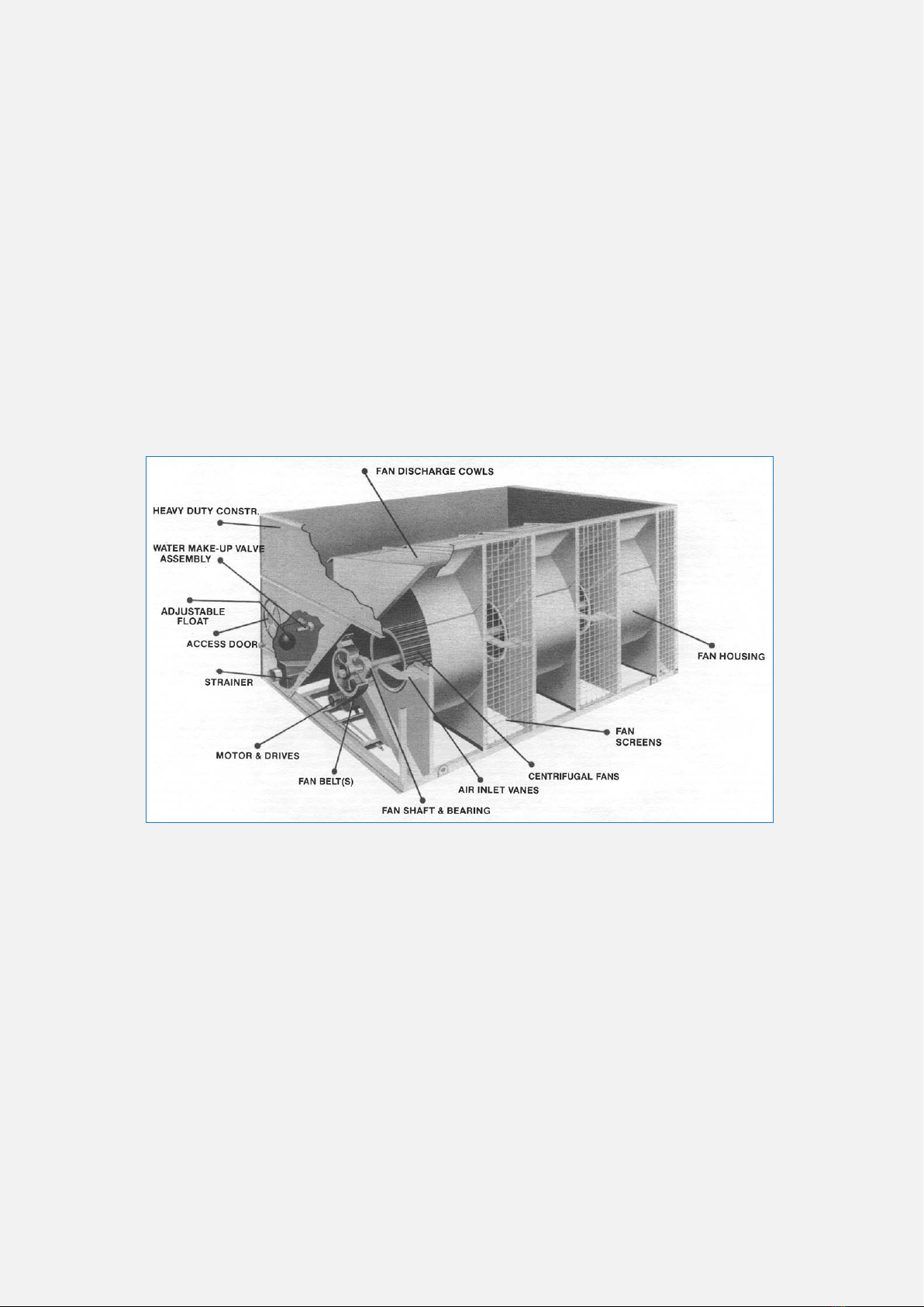
1. Clean any debris from inlet air screens, fans, water basin.
2. Flush the cold water sump (with sump strainers in place) and drain
to remove accumulated dirt.
3. Remove, clean, and replace sump strainers.
4. Turn the fan by hand to ensure rotation without obstruction.
5. Check and, if necessary, adjust the fanbelt tension.
6. Prior to seasonal start-up, lubricate the fan shaft and motor bearings.
The ball bearings are factory lubricated, but should be relubricated if
the unit has been sitting on site for more than a year before start-up.
7. Check oat operated make-up valve to be sure it is operating freely.
8. Fill cold water sump with fresh water to the overow level.
9. Set the oat on the make-up valve to shut off the valve when the
oat is approximately 10mm below the overow level.
10. On VXI-S Industrial Fluid Coolers and VXC-S Evaporative
Condensers, start the pump and check for the proper rotation as
indicated by the arrow on the pump cover. On installations where the
unit pump was not furnished by the factory, a globe valve should be
installed in the pump discharge line and the pump ow rate adjusted
to the correct water ow. Do not run pump dry.
11. Inspect spray nozzles and heat transfer section.
12. Check the locking collar on each fan bearing assembly and tighten
as required.
13. Start the fan and check for the proper rotation as indicated by the
arrow on the fan housing.
14. Check the voltage and current of all three legs of the fan and pump
motors. The current should not exceed the nameplate rating. After
prolonged shutdowns, the motor insulation should be checked with a
megger insulation tester prior to re-starting the motor.
15. Open the bleed line valve (must be furnished by others on cooling
tower models VXT-N215 through VXT-4800) and adjust bleed to the
recommended rate (See “Water Treatment”).
WARNING: Rapid on/off cycling
can cause the fan motor to
overheat. Controls should be set
to allow a maximum of six on/off
cycles per hour.

4
WWW.BALTIMOREAIRCOIL.COM.AU
MAR113-0
WARNING: Do not perform any
service on or near the fans,
motors, and drives, or inside the
unit without rst ensuring
that the fans and the pumps are
disconnected and locked out.
After 24 Hours
After 24 hours of operating under load, the following services should
be performed.
1. Check the unit for any unusual noise or vibration.
2. Check the operating water level in the cold water sump. Adjust the
make up oat valve if necessary.
3. Readjust the belt tension.
4. Inspect spray nozzles and heat transfer section.
Operation
During operation, the unit should be inspected, cleaned, and
lubricated on a regular basis, as per the ‘Recommended Maintenance
Service Table’ in this bulletin.

5
WWW.BALTIMOREAIRCOIL.COM.AU
MAR113-0
Operation and Maintenance
After 24 Hours
Operation
Seasonal Shutdown
Seasonal Shutdown
The following services should be performed when the unit is to be
shutdown for a prolonged period:
1. Drain the cold water sump and all piping that will be exposed to
freezing temperatures.
2. Clean and ush the cold water sump with the sump strainers in
place. Leave the drain open so rain and melting snow will drain from
the unit.
3. Clean the sump strainers and re-install.
4. Lubricate the fan shaft and motor bearings, motor base and motor
base adjusting screw.
5. Close shut-off valve in water make-up line and drain all exposed
make-up piping.
6. Inspect the protective nish on the unit. Clean and renish as
required.
7. If operating VXI-S coolers in cold climates see section on cold
weather operation and consult your B.A.C. representative about
protection against coil freezing.

VX SERIES
Maintenance Procedures
COLD WATER SUMP
MAKE-UP VALVE
FAN SHAFT BEARINGS
BALL BEARINGS
SPRAY NOZZLES AND HEAT TRANSFER SECTION
CORROSION PROTECTION
LOCKING COLLARS
ADJUSTABLE MOTOR BASE
FAN DRIVES
2

7
WWW.BALTIMOREAIRCOIL.COM.AU
MAR113-0
Maintenance Procedures
Cold Water Sump
Make-Up Valve
Cold Water Sump
The cold water sump should be inspected regularly. Any trash or debris
which may have accumulated in the sump or on the strainers should
be removed.
Each month, the entire cold water sump should be drained, cleaned,
and ushed with fresh water to remove the silt and sediment which
normally collects in the sump during operation. If not removed
periodically, this sediment can become corrosive and cause
deterioration of the protective nish. When ushing the sump,
the strainers should be left in place to prevent the sediment from
reentering the system. After the sump has been ushed, the strainers
should be removed, cleaned, and replaced before relling the sump
with fresh water. The strainers can be removed by pulling the handle
up and away from the outlet connection. NOTE: Do not use acid to clean the
strainers.
Make-Up Valve
A oat operated water make-up (See Figure 1) is furnished as standard
equipment on all units unless the unit has been ordered with an
electric water level control or for remote sump application. The oat
controlling the valve is mounted on a threaded rod, held in place by
wing nuts to facilitate adjustment of the operating water level.
To make the initial setting, adjust the wing
nuts so that the make-up valve is completely
closed when the water level in the cold
water sump is 10mm below the overow
level. This will ensure that the tower sump
contains enough water volume to prevent air
entrainment in the circulating pump during
system start-up. Under normal thermal load
and with average city water pressure at the
valve (15 to 50 psig), this setting should
produce an operating water level as shown in
Table 2 and Figure 1A.
Figure 1 - Water Make-up Valve Assembly

8
WWW.BALTIMOREAIRCOIL.COM.AU
MAR113-0
Model Number Operating Level (mm)
measured from the pan (bottom)
VXT-10 TO 135 327mm
VXI-S9, 18, 27, 36 343MM
VXC-S14 to S135 343mm
VXT-150 to 185 394mm
VXI-S50 419mm
VXC-S150 to S205 419mm
VXT-N215 to N535 432mm
VXI-S70, 95, 145, 190, 290 432mm
VXC-S221 to 265 & VXC-S288 to 1010 432mm
VXT-315 to 4800 457mm
VXI-S180, 360 457mm
VXC-S357 to 1360 457mm
VXC-S495 to 1608 356mm
VXI-S144, 215, 288, 430 356mm
Table 2 - Operating Water Level
The water level in the cold water sump will vary as a function of the
system load (evaporation rate), bleed rate, supply water pressure, and
the quantity of water suspended in the tower during pump operation
plus that contained in the water distribution system, external piping,
and any heat exchangers which could drain to the tower sump when
the circulating pump is shut down. Because the typical winter load is
less than the summer load, the winter evaporation rate is frequently
less than the summer evaporation rate. With this reduced evaporation
rate in the winter, the water level in the cold water sump will
increase unless the oat is
readjusted.
Due to these variables the
operating water level should
be checked monthly and the
oat adjusted as necessary
to maintain the desired
operating level. The valve
itself should be inspected
annually for leakage and
the valve seat replaced if
necessary.
Figure 1a - Operating Water Level

9
WWW.BALTIMOREAIRCOIL.COM.AU
MAR113-0
Maintenance Procedures
Make-Up Valve (cont.)
Fan Shaft Bearings
Ball Bearings
WARNING: Do not use oils
containing detergents for bearing
lubrication. Detergent oils will
remove graphite in the bearing
sleeve and cause bearing failure.
Also, do not disturb bearing
alignment by tightening bearing
cap adjustment on a new unit as
they are torque adjusted at the
factory.
Figure 1a - Operating Water Level
Fan Shaft Bearings
The fan shaft is supported at each end by ball bearings (See Figure 2),
each equipped with a lubrication tting and locking collar.
Models VXT-65 through 135, VXI-S27 and 36, and VXCS-72 through
135 also have intermediate ball bearing(s) located midway on the shaft.
Ball Bearings
Under normal operating conditions, the bearings should be greased
every 2,000 operating hours or at least every six months. The bearings
should also be greased at seasonal start-up and shutdown. Lubricate the
bearings only with one of the following water resistant inhibited greases
which are good for ambient temperatures ranging from -54°C to 120°C
American - Rycon Premium #3
Exxon - Beacon #325
Shell - Aeroshell #17
Mobil - Mobilgrease #28
Chevron - SRI #3
Keystone - 84 EP Light
The bearings should be lubricated only with a hand grease gun. Do not
use high pressure grease guns since they may rupture the bearing seals.
When lubricating, purge the old grease from the bearing by gradually
adding grease until a bead of new grease appears at the seal.
Figure 2 - Ball Bearing

10
WWW.BALTIMOREAIRCOIL.COM.AU
MAR113-0
Figure 8. Nozzle Spray Distribution
Spray Nozzles And Heat Transfer Section
The spray nozzles and heat transfer section should be inspected and
cleaned each month. The inspection procedure is as follows:
1. Shut off the fan, but leave the pump running.
2. Remove the eliminators.
3. Check to see if the nozzles are producing the spray pattern shown
in Figure 8.
4. Clean any nozzles which are clogged. If necessary, the nozzle and
rubber grommet may be removed for cleaning.
5. Inspect the coil or wet deck surface. Any corrosion, damage, or
obstructions must be corrected.
NOTE: Do not use steam or high
pressure water to clean cooling
tower wet deck surface other
than steel.

11
WWW.BALTIMOREAIRCOIL.COM.AU
MAR113-0
Maintenance Procedures
Spray Nozzles and Heat Transfer
Section
Corrosion Protection
VX units are constructed entirely of corrosion resistant materials. The wet
deck surface is made of an inert synthetic material which requires no
protection against rot, decay, rust or biological attack.
Standard
The standard VX unit has steel components of heavy gauge galvanized
steel. The exterior of the cooling tower is nished with an etch primer
covered with a heavy duty fast drying enamel after fabrication. These
units should be inspected annually.
Inspect the inside of the tower for blemishes or corrosion on the
galvanized steel. Affected areas should be thoroughly wire brushed and
recoated with ZRC (zinc-rich compound).
The outside of the tower can be touched up if necessary. ZRC is available
from your local B.A.C. Representative.
Optional
As an option, the VX unit can have 304SST components substituted for
galvanised steel everywhere. Various congurations of SST substitution
are available.
Please consult your local B.A.C. representative for details.

12
WWW.BALTIMOREAIRCOIL.COM.AU
MAR113-0
Locking Collars
Each eccentric locking collar should be checked every six months to
ensure that the inner bearing race is secured to the fan shaft. The
locking collar can be set using the following procedure (See Figure 9):
1. Loosen the set screw.
2. Using a drift pin or centrepunch, tap the collar (in the hole provided)
tangentially in the direction of rotation while holding the shaft.
3. Retighten the set screw.
Figure 9. Locking Collar Assembly
Adjustable Motor Base
The motor base slides and adjusting screw (See Figure 10) should be
coated twice a year using a good quality corrosion inhibiting grease, such
as one of those recommended for lubricating the fan shaft bearings.
Figure 10. Adjustable Motor Base

13
WWW.BALTIMOREAIRCOIL.COM.AU
MAR113-0
Fan Drives
The fan belt should be checked and
adjusted every month. To properly
adjust the belt tension, position
the fan motor so that a single belt
will deect 10mm when moderate
pressure of one nger is applied
midway between the sheaves (See
Figure 12). The position of the fan
motor can be changed by rotating
the motor base adjusting screw
which extends through the bottom
frame angle.
The drive alignment should be
checked annually to ensure
maximum belt life. This can be
done by placing a straightedge
across both sheaves as shown in
Figure 7.
When the drive is properly aligned, the straightedge will contact all
four points as indicated. If realignment is necessary, loosen the motor
sheave and align it with the fan sheave. Allow approximately 6mm
for draw-up as the motor sheave is pulled tight on the bushing; then
retighten the bushing screw.
Figure 11. Fan Belt Adjustment
Detailed Component
Maintenance Procedures
Locking Collars
Adjustable Motor Base
Fan Drives
NOTE: There should be no ‘chirp’
or ‘squeal’ when the fan motor is
started.
Figure 12. Checking Sheave Alignment

VX SERIES
Water Treatment
BLEED OFF
BIOLOGICAL CONTROL
3
Table of contents
Other BAC Industrial Equipment manuals