Fike SRX User manual

INSTALLATION AND MAINTENANCE INSTRUCTIONS
Reverse Acting Rupture Disc Assemblies
Rupture Disc Models: SRX, SRL, Axius, ATLAS, AGT
Holder Models: SRX, SRL/SRL , XL/XL , ATLAS/ATLAS-L
704 SW 10th Street · P. . Box 610 · Blue Springs, Missouri 64013-0610 U.S.A. · (816) 229-3405 · www.fike.com
Page 1
06
-
251
-
1
WARNING
• Read these instructions carefully and completely before
attempting to unpack, install or service the rupture disc
and holder.
• Do not vent a rupture disc assembly to an area where it
would endanger personnel.
• Install the rupture disc assembly in such a way that
equipment in the area will not prevent rupture disc from
opening or be damaged by system discharge.
• A baffle plate on the outlet end of vent piping does N T
necessarily prevent potentially dangerous discharge.
• Piping should be braced to absorb shock when the rupture
disc ruptures.
• Install the enclosed DANGER sign in a conspicuous
location near the zone of potential danger.
• 1” (DN25) Axius is not suitable for liquid systems at burst
pressures less than 20 PSIG (1.38 BARG) with an inlet
piping length greater than 10 IN (25 cm)
• ¾” (DN20) Axius is not suitable for liquid systems at burst
pressures less than 30 PISG (2.07 BARG) with an inlet
piping length greater than 8 IN (20 cm)
• ATLAS not suitable for liquid systems in sizes 14” and
larger.
• Spiral wound gaskets are not suitable for the following
sizes and flange ratings:
• 1” (DN20 & DN25) – All flange ratings
• 1.5” (DN40) – 900-2500 ANSI and JIS 40k, 63k
• 2” (DN50) – 900-2500 ANSI and JIS 30k, 40k, 63k
• 3” (DN80) – JIS 30k, 40k, 63k
• 4” (DN100) – JIS 30k, 40k, 63k
• If the rupture disc features a fluoropolymer liner, do not
remove this component.
NOTE: Rupture disc specifications and year of manufacture
can be found on the rupture disc tag.
TABLE 1 - DISC/HOLDER MODEL COMPATIBILITY
Disc
Model
Holder Model
SRX SRL/
SRL
XL/
XL
ATLAS/
ATLAS-L
SRX
SRL *
Axius **
ATLAS
AGT
*1.5" SRL disc not compatible with 1.5” XL/XL holder
**1.5" Axius disc not compatible with 1.5” SRL/SRL holder
INSPECTION/PREPARATION
A. NEW RUPTURE DISCS
WARNING: Always handle the rupture disc with extreme
caution. Nicks, dents, scratches or foreign material may result
in leakage or affect the burst pressure. Read the rupture disc
tag completely before installing to confirm that the size and
type are correct for your system.
1. Carefully remove the rupture disc from its packaging
container.
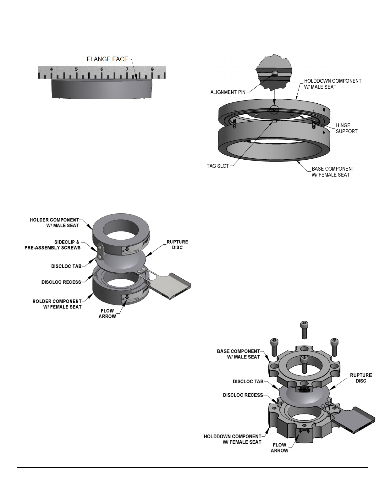
2. Inspect the rupture disc for damage. Look for dents,
scratches or dings in the seat area or dents in the dome of
the rupture disc (See Figure 1).
3. If foreign material is present, carefully clean the rupture
disc with a solvent that is compatible with your media.
Figure 1 - C eck for Damage
NOTE: Handle rupture disc olders wit care. Damage to
t e rupture disc older could affect t e performance of t e
rupture disc. Do not install or use a rupture disc t at as
been damaged!
B. NEW HOLDER
1. Carefully take the rupture disc holder apart by removing
the sideclips or capscrews and discard the white shipping
protector (See Figure 2).
2. Inspect the seat area for scratches, dents, nicks or dirt.
Flaws may adversely affect sealing and burst pressure.
3. If necessary, clean dust or dirt on the seat area with a
solvent that is compatible with your media.
Figure 2 - Insert Holder (Top) and Pre-torqueable Holder
C. EXISTING HOLDER
1. For insert style holders, carefully remove the rupture disc
assembly from piping.
2. Separate rupture disc holder components.
3. Remove old rupture disc.
4. Inspect the seat area of the rupture disc holder. Look for
scratches, nicks, corrosion or deposits left from the media.
704 SW 10th Street · P. . Box 610 · Blue Springs, Missouri 64013-0610 U.S.A. · (816) 229-3405 · www.fike.com
Page 2
5. Check to make sure the gasket faces of the assembly are
flat by placing a straight edge across the face. If faces are
not flat, holder is not suitable for use (See Figure 3).
Figure 3 - Measuring for Flatness
6. If necessary, clean the seat area with a solvent that is
compatible with your media. If this does not remove dirt,
hand polish the seat area with Scotch Brite fine emery
cloth or #0000 steel wool. D N T MACHINE THE
RUPTURE DISC H LDER! If scratches, nicks, corrosion,
or deposits cannot be removed by hand, contact the
factory.
ASSEMBLY
WARNING: Before attempting to assemble the rupture disc
and rupture disc holder, confirm that the seat area of the
rupture disc is designed to fit the rupture disc holder.
1. Place holder component with female seat on a work
surface (See Figures 4, 5, & 6).
Figure 4 - Insert Holder
2. If the holder was supplied with an optional o-ring groove,
install an o-ring into the groove of the component with the
female seat. Note: Use of an o-ring is for improved sealing
and is not required for proper function of the rupture disc
assembly. Do not install an o-ring unless the holder is
designed to accept these components by Fike!
3. Place rupture disc into holder component with female seat
with flow arrow on tag pointing in the same direction as
holder component with female seat flow arrow.
DiscLoc
TM
tab, if present, must seat properly in recess.
4. If the holder was supplied with an optional o-ring groove,
install an o-ring into the groove of the component with the
male seat. Note: Use of an o-ring is for improved sealing
and is not required for proper function of the rupture disc
assembly. Do not install an o-ring unless the holder is
designed to accept these components by Fike!
5. Carefully align and place holder component with male seat
onto rupture disc with flow arrow in the same direction as
disc and holder component with female seat flow arrows.
CAUTION: Be careful to not allow the male seat
component to strike or damage the dome of the rupture
disc!
Figure 5 – Alignment pin fitting in tag slot. (ATLAS sizes
14” and larger”)
WARNING: For ATLAS sizes 14” and larger, ensure that
the alignment pin in the holddown fits into the tag slot of
base (see Figure 5) and check the gap (see Figure 7).
Fragmentation or leaking can occur if this feature is not
aligned properly.
6. Rotate component with male seat to align sideclip holes.
7. If holder configuration is Insert, install sideclips and tighten
securely.
8. If holder configuration is TQ, turn assembly over to access
capscrew holes (depending on design).
Note: It may be beneficial to move/tilt or support the
holder to first install a few capscrews evenly around the
perimeter before turning the assembly over.
9. If holder configuration is TQ or TQ+, lubricate uncoated
capscrews with a light oil such as SAE grade 20. Lubricate
both the threads and the underside of the head. Install
lubricated capscrews and tighten until recessed and snug
in the holder (see Figure 6).
704 SW 10th Street · P. . Box 610 · Blue Springs, Missouri 64013-0610 U.S.A. · (816) 229-3405 · www.fike.com
Page 3
Figure 6 – Pre-torqueable Holder
(TQ+ configuration s own)
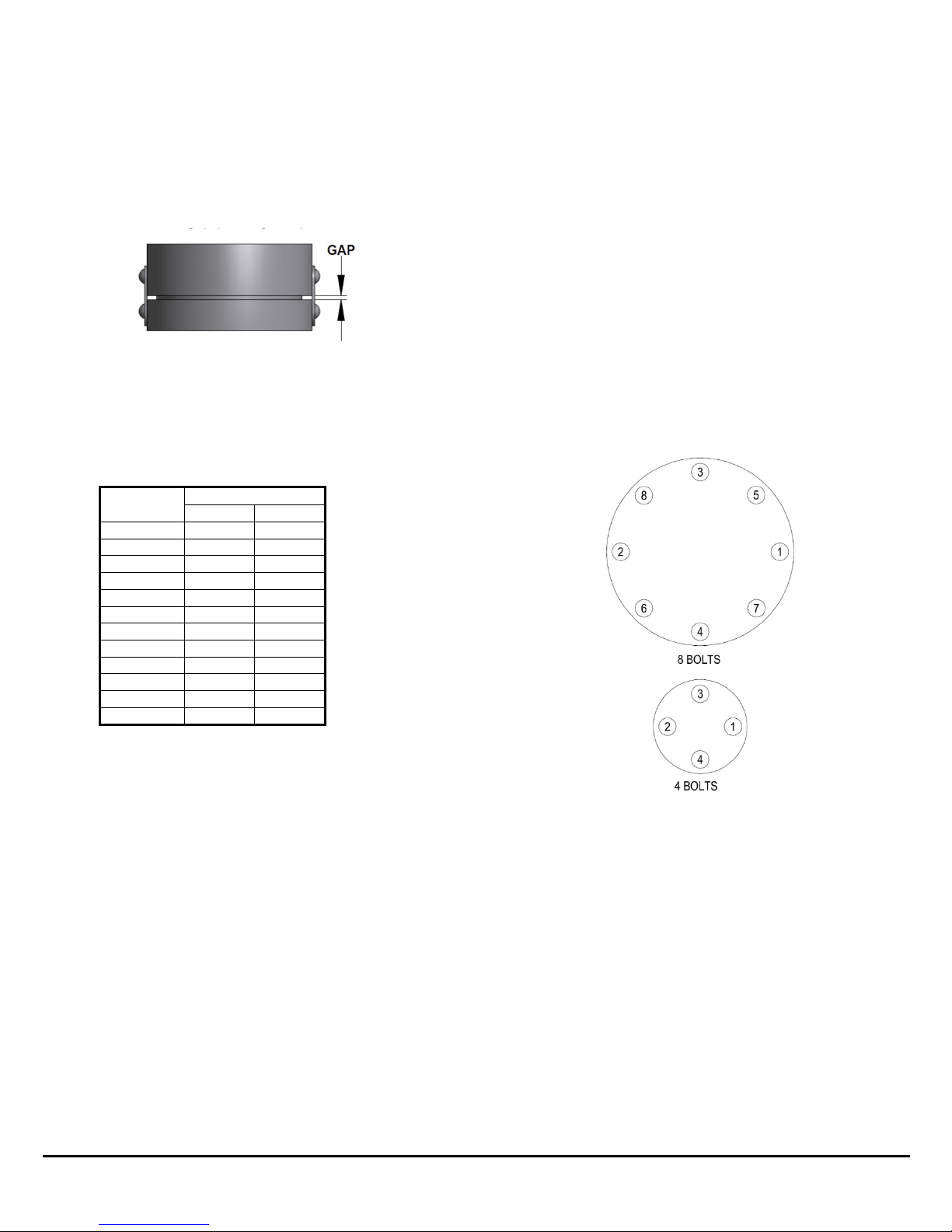
10. Check gap between base and holddown. The gap must be
the same size on all sides of the assembly. This can be
assured by measuring the distance between the holddown
and base at various places around the circumference of
the assembly. Adjust pre-assembly screws if necessary to
provide an even gap (See Figure 7).
Figure 7 - Gap Inspection
11. If holder configuration is TQ or TQ+, torque capscrews to
values shown in Table 2 using crisscross pattern in 20%
increments until the full torque is achieved on all
capscrews.
Note: Torque values are based on a nut factor, K = 0.20.
12. If holder configuration is TQ or TQ+, reconfirm the gap per
step 10 after the capscrews are torqued per Table 2.
INSTALLATION
1. Place gaskets on top and bottom of assembly. Gaskets
subject to relaxation or cold flow are not recommended for
use with the holder assembly. Spiral wound gaskets are
not suitable for certain sizes and flange ratings. Reference
warning notes on page 1.
2. Carefully slide rupture disc assembly between companion
flanges.
WARNING: For installations directly under a pressure relief
valve that utilize a spool/spacer, ensure spool/spacer is
installed between the outlet of the holder and inlet of the
pressure relief valve. SRL , XL , and ATLAS-L holder
sizes 12” and smaller are not suitable for direct-coupling to a
pressure relief valve; they must utilize a high-profile holddown,
spool, or a suitable spacer. Atlas holders 14” and larger
require a spool piece if under a pressure relief valve. Refer to
Fike Technical Bulletin TB8105 for code requirements.
WARNING: Double check the orientation of the rupture disc.
Verify flow arrows on the holder and disc tag are pointed in the
same direction as process flow.
3. If necessary, clean threads on studs and nuts. Wire
brushing is usually sufficient. il studs with a light oil such
as SAE grade 20. Do not use studs and nuts that show
evidence of galling.
4. Finger-tighten flange studs and nuts.
5. Refer to Appendix A to obtain torque value. Locate
nominal disc size and flange rating. This is the
recommended torque value.
6. Using the crisscross pattern shown in Figure 8, apply
torque in 4 steps of 25% increments. For example, if the
torque required from Appendix A is 100 ft-lb, the torque
should be applied in 25 ft-lb increments. Apply 25 ft-lb to
each nut, then 50 ft-lb, then 75 ft-lb, etc. For larger
quantities of bolts than shown below, use a similar
crisscross pattern.
NOTE: Follow the torque instructions in this document
unless a specific torque requirements is stated on the
Rupture Disc and/or Rupture Disc Holder Tag.
Figure 8 - Bolt Tig tening Sequence
7. After recommended torque has been achieved, perform a
final tightening in a clockwise bolt-to-bolt fashion to ensure
that all studs have equal loading.
CHECK GAP BETWEEN BASE AND H LDD WN AFTER
EACH T RQUE STEP. MAINTAIN AN EQUAL DISTANCE
BETWEEN C MPANI N FLANGE FACES N ALL SIDES.
8. Experience has shown that, in some installation
conditions, it may be necessary to re-torque the flange
bolting after the system has operated through normal
pressure and temperature cycles. Under normal operating
conditions, the rupture disc is recommended to be
replaced yearly. Severe operating conditions may require
that the rupture disc be replaced more often.
Capscrew
Size
Torque
ft-lb N-m
1/4” 4 5
5/16” 8 11
3/8” 12 16
7/16” 20 27
1/2” 30 41
5/8” 60 81
3/4” 100 136
7/8” 160 217
M8 10 14
M10 17 23
M12 29 39
M24 221 300
Table 2
–
TQ & TQ+ Capscrew Torque
704 SW 10th Street · P. . Box 610 · Blue Springs, Missouri 64013-0610 U.S.A. · (816) 229-3405 · www.fike.com
Page 4
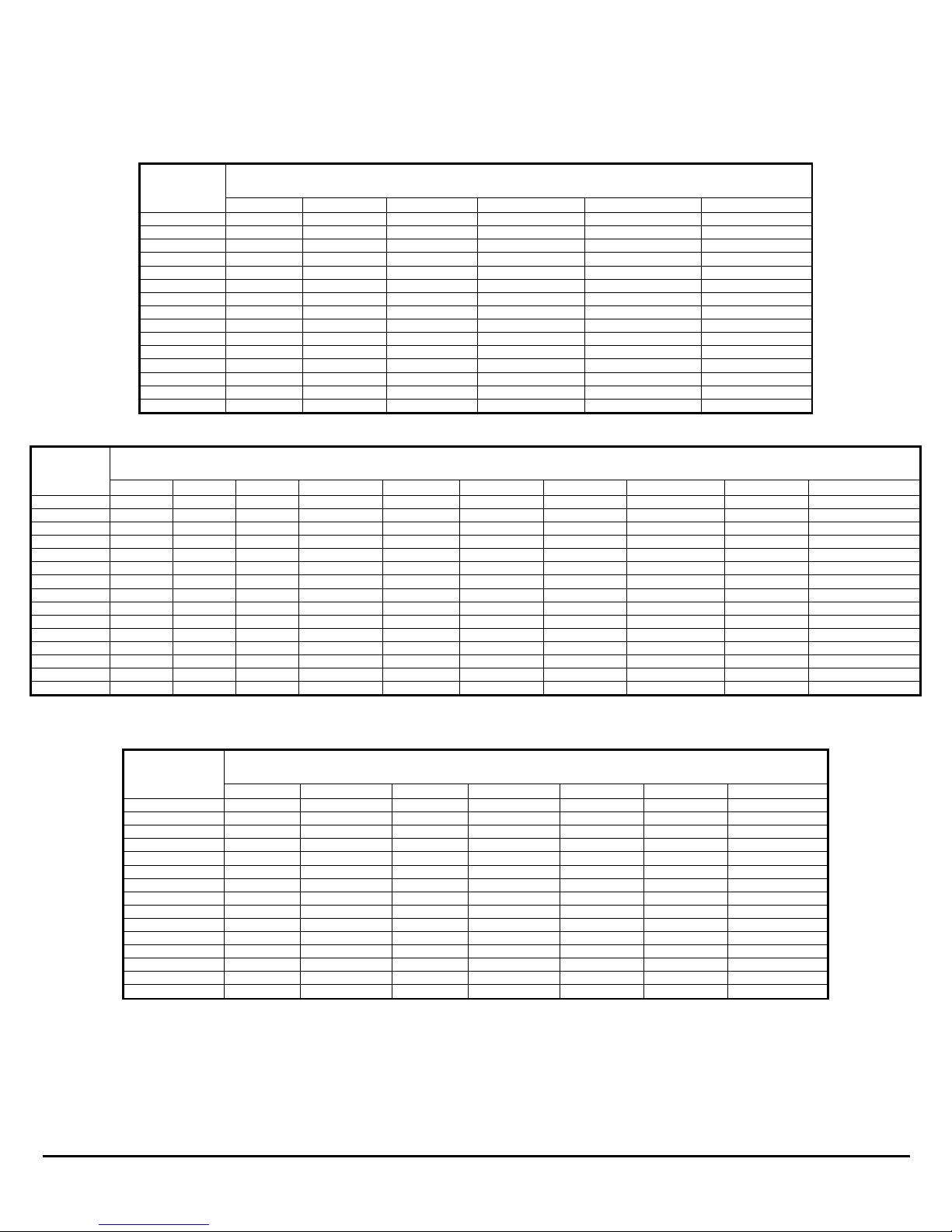
Appendix A – Stud Torque Values
NOTE: Torque values in Appendix A are based on a nut factor K= 0.2. Adjustment to the torque should be considered if the installation
utilizes bolting/lubrication with a nut factor other than K= 0.2. The following expression may be used for correction:
Equation 1: T
2
= (T
1
/K
1
)*K
2
where T
1
and K
1
are the Fike default torque and nut factor values.
NOTE: Torque values in Tables 1 to 3 are recommended values, but may be increased up to 50% to achieve an increased gasket seal.
If the torque values are unsatisfactory, consult factory.
Nominal
Pipe Size
(in)
Torque by Flange Rating
(ft-lb [N-m])
150 ANSI 300 ANSI 600 ANSI 900 ANSI 1500 ANSI 2500 ANSI
.75 30 [41] 60 [81] 60 [81] N/A N/A N/A
1” 30 [41] 60 [81] 60 [81] 160 [217] 160 [217] 160 [217]
1.5 30 [41] 100 [136] 100 [136] 245 [332] 245 [332] 355 [481]
2 60 [81] 60 [81] 60 [81] 160 [217] 160 [217] 245 [332]
3 60 [81] 100 [136] 100 [136] 160 [217] 355 [481] 500 [678]
4 60 [81] 100 [136] 160 [217] 355 [481] 500 [678] 800 [1,085]
6 100 [136] 100 [136] 245 [332] 355 [481] 680 [922] 2,200 [2,983]
8 100 [136] 160 [217] 355 [481] 680 [922] 1,100 [1,491] 2,200 [2,983]
10 160 [217] 245 [332] 500 [678] 680 [922] 2,000 [2712] 4,400 [5,966]
12 160 [217] 355 [481] 500 [678] 680 [922] 2,200 [2,983] 5,920 [8,026]
14 245 [332] 355 [481] 680 [922] 800 [1,085] 3,180 [4,312] N/A
16 245 [332] 500 [678] 800 [1085] 1,100 [1,491] 4,400 [5,966] N/A
18 355 [481] 500 [678] 1100 [1491] 2,000 [2712] 5,920 [8,026] N/A
20 355 [481] 500 [678] 1100 [1491] 2,200 [2,983] 7,720 [10,467] N/A
24 500 [678] 800 [1085] 2000 [2712] 4,400 [5,966] 11,651 [15,797] N/A
Nominal
Pipe Size
(in [mm])
Torque by Flange Rating
(ft-lb [N-m])
PN 6 PN 10 PN 16 IS PN 20 PN 25 PN 40 IS PN 50 DIN PN 63/64 DIN PN 100 IS PN 100/110
.75 [DN20] 23 [31] 28 [37] 28 [37] 32 [44] 45 [61] 45 [61] 60 [82]
N/A
N/A
60 [82]
1” [DN 25] 23 [31] 28 [37] 28 [37] 32 [44] 45 [61] 45 [61] 60 [82] 60 [82] 60 [82] 60 [82]
1.5 [DN 40] 28 [37] 37 [50] 37 [50] 32 [44] 84 [114] 84 [114] 105 [142] 105 [142] 105 [142] 105 [142]
2 [DN 50] 45 [61] 60 [82] 60 [82] 60 [82] 121 [164] 121 [164] 60 [82] 151 [205] 181 [246] 60 [82]
3 [DN 80] 60 [82] 30 [41] 30 [41] 60 [82] 84 [114] 84 [114] 105 [142] 105 [142] 126 [171] 105 [142]
4 [DN 100] 121 [164] 60 [82] 60 [82] 60 [82] 105 [142] 105 [142] 105 [142] 173 [235] 195 [264] 173 [235]
6 [DN 150] 84 [114] 105 [142] 105 [142] 105 [142] 189 [256] 189 [256] 105 [142] 433 [587] 289 [391] 260 [352]
8 [DN 200] 84 [114] 105 [142] 70 [95] 105 [142] 173 [235] 195 [264] 173 [235] 410 [555] 410 [555] 372 [505]
10 [DN 250] 115 [157] 144 [196] 173 [235] 173 [235] 347 [470] 385 [523] 260 [353] 693 [939] 756 [1,025] 520 [705]
12 [DN 300] 144 [196] 144 [196] 173 [235] 173 [235] 336 [455] 373 [505] 373 [505] 650 [881] 768 [1,041] 520 [705]
14 [DN 350] 192 [261] 144 [196] 173 [235] 260 [352] 466 [632] 513 [695] 372 [504] 875 [1,187] 1,094 [1,484] 700 [950]
16 [DN 400] 192 [261] 231 [314] 260 [353] 260 [353] 650 [881] 709 [961] 520 [705] 1,024 [1,388] N/A 819 [1,110]
18 [DN 450] 249 [337] 239 [323] 268 [364] 373 [505] 624 [846] 680 [922] 520 [705] N/A N/A 1,119 [1,517]
20 [DN 500] 249 [337] 298 [405] 373 [506] 372 [504] 624 [846] 737 [999] 520 [705] N/A N/A 1,120 [1,518]
24 [DN 600] 378 [512] 425 [576] 520 [705] 520 [705] 907 [1,230] 1,134 [1,537] 819 [1,110] N/A N/A 2,016 [2,733]
Nominal Pipe
Size (in [mm])
Torque by Flange Rating
(ft-lb [N-m])
JIS 5 JIS 10 JIS 16 JIS 20 JIS 30 JIS 40 JIS 63
.75 [DN20] N/A 28 [37] 28 [37] 60 [82] N/A N/A N/A
1” [DN 25] 23 [31] 37 [50] 37 [50] 60 [82] 60 [82] 60 [82] 75 [102]
1.5 [DN 40] 28 [37] 37 [50] 37 [50] 84 [114] 105 [142] 105 [142] 115 [157]
2 [DN 50] 45 [61] 60 [82] 60 [82] 60 [82] 60 [82] 60 [82] 75 [102]
3 [DN 80] 60 [82] 30 [41] 30 [41] 105 [142] 105 [142] 105 [142] 115 [157]
4 [DN 100] 60 [82] 60 [82] 75 [102] 105 [142] 115 [157 115 [157] 173 [235]
6 [DN 150] 84 [114] 105 [142] 77 [104] 115 [157] 126 [171] 157 [214] 289 [391]]
8 [DN 200] 105 [142] 70 [95] 77 [104] 159 [215] 173 [235] 217 [294] 372 [505]
10 [DN 250] 144 [196] 159 [215] 173 [235] 308 [418] 385 [523] 385 [523] 756 [1,025]
12 [DN 300] 144 [196] 119 [161] 130 [176] 298 [404] 373 [505] 447 [607] 709 [961]
14 [DN 350] 212 [287] 159 [215] 217 [294] 465 [631] 465 [631]] 558 [757] 1,021 [1,385]
16 [DN 400] 212 [287] 231 [314] 289 [392] 591 [801] 709 [961] 709 [961] 1,102 [1,495]
18 [DN 450] 273 [370] 239 [323] 298 [404] 567 [769] N/A N/A N/A
20 [DN 500] 273 [370] 298 [404] 372 [504] 567 [769] N/A N/A N/A
24 [DN 600] 378 [512] 394 [534] 472 [641] 756 [1,025] N/A N/A N/A
Table 1
–
Stud Torque Values
–
ASME
(SRX, SRL
/SRLO
, XL
/XLO
)
Table
2
–
Stud Torque Values
–
EN/
ISO/DIN (SRX, SRL
/SRLO
, XL
/XLO
)
Table 3
–
Stud Torque Values
–
JIS
(SRX, SRL
/SRLO
, XL
/XLO
)

704 SW 10th Street · P. . Box 610 · Blue Springs, Missouri 64013-0610 U.S.A. · (816) 229-3405 · www.fike.com
Copyright © Fike Corporation All Rights Reserved.
P/N 06-251-1-26 May, 2018 Specifications are subject to change without notice. Page 5
NOTE: Torque values for Atlas sizes 14” and larger in Tables 4 to 6 were determined by considering ASME PCC-1 and ASME Section
VIII Division 1 Mandatory Appendix II guidelines. Torque values in Appendix A are based on a nut factor K= 0.2. Adjustment to the
torque should be considered if the installation utilizes bolting/lubrication with a nut factor other than K= 0.2. The following expression
may be used for correction:
Equation 1: T
2
= (T
1
/K
1
)*K
2
where T
1
and K
1
are the Fike default torque and nut factor values.
Nominal
Pipe
Size (in)
Torque by Flange Rating
(ft-lb [N-m])
150
ANSI
300
ANSI
600
ANSI
900
ANSI
1500
ANSI
2500
ANSI
Series B
75
Series B
150
Series B
300
Series A
150
Series A
300
1” 30 [41] 60 [81] 60 [81] 160 [217] 160 [217] 160 [217] N/A N/A N/A N/A N/A
1.5 30 [41] 100 [136] 100 [136] 245 [332] 245 [332] 355 [481] N/A N/A N/A N/A N/A
2 60 [81] 60 [81] 60 [81] 160 [217] 160 [217] 245 [332] N/A N/A N/A N/A N/A
3 60 [81] 100 [136] 100 [136] 160 [217] 355 [481] 500 [678] N/A N/A N/A N/A N/A
4 60 [81] 100 [136] 160 [217] 355 [481] 500 [678] 800 [1,085] N/A N/A N/A N/A N/A
14 459 [622] 682 [925] 1,323 [1,794] N/A N/A N/A N/A N/A N/A N/A N/A
16 459 [622] 968 [1,312] 1,581 [2,144] N/A N/A N/A N/A N/A N/A N/A N/A
18 682 [925] 968 [1,312] 2,275 [3,084] N/A N/A N/A N/A N/A N/A N/A N/A
20 682 [925] 968 [1,312] 1,593 [2,160] N/A N/A N/A N/A N/A N/A N/A N/A
24 968 [1,312] 984 [1,334] 1,947 [2,640] N/A N/A N/A N/A N/A N/A N/A N/A
26 N/A N/A N/A N/A N/A N/A N/A 189 [256] 871 [1,181] 484 [656] 1,365 [1,851]
28 N/A N/A N/A N/A N/A N/A N/A 159 [216] 527 [715] 419 [568] 1,493 [2,024]
30 N/A N/A N/A N/A N/A N/A N/A 154 [209] 722 [979] 418 [567] 1,556 [2,110]
32 N/A N/A N/A N/A N/A N/A N/A 150 [203] 958 [1,299] 703 [953] 1,968 [2,668]
36 N/A N/A N/A N/A N/A N/A N/A 260 [353] 1,365 [1,851] 703 [953] 2,652 [3,596]
42 N/A N/A N/A N/A N/A N/A N/A 321 [435] 2,020 [2,739] 703 [953] 1,593 [2,160]
Nominal
Pipe Size
(in [mm])
Torque by Flange Rating
(ft-lb [N-m])
PN
1, 2 & 6 PN 10 PN 16 IS
PN 20 PN 25 PN 40 IS
PN 50
DIN
PN 63/64
DIN
PN 100
IS
PN 100/110
1” [DN 25] 23 [31] 28 [37] 28 [37] 32 [44] 45 [61] 45 [61] 60 [82] 60 [82] 60 [82] 60 [82]
1.5 [DN 40] 28 [37] 37 [50] 37 [50] 32 [44] 84 [114] 84 [114] 105 [142] 105 [142] 105 [142] 105 [142]
2 [DN 50] 45 [61] 60 [82] 60 [82] 60 [82] 121 [164] 121 [164] 60 [82] 151 [205] 181 [246] 60 [82]
3 [DN 80] 60 [82] 30 [41] 30 [41] 60 [82] 84 [114] 84 [114] 105 [142] 105 [142] 126 [171] 105 [142]
4 [DN 100] 121 [164] 60 [82] 60 [82] 60 [82] 105 [142] 105 [142] 105 [142] 173 [235] 195 [264] 173 [235]
14 [DN 350] N/A 224 [304] 349 [473] 575 [780] 612 [830] 893 [1,211] 816 [1,106] 1,259 [1,707] 2,126 [2,882] 1,333 [1,807]
16 [DN 400] N/A 310 [420] 460 [624] 575 [780] 781 [1,059] 963 [1,306] 1,116 [1,513] 1,646 [2,232] N/A 1,646 [2,232]
18 [DN 450] N/A 240 [325] 288 [390] 816 [1,106] 670 [908] 815 [1,105] 1,116 [1,513] N/A N/A 2,313 [3,136]
20 [DN 500] N/A 277 [376] 354 [480] 816 [1,106] 608 [824] 1,058 [1,434] 1,116 [1,513] N/A N/A 1,948 [2,641]
24 [DN 600] N/A 374 [507] 460 [624] 1,116 [1,513] 807 [1,094] 1,326 [1,798] 1,085 [1,471] N/A N/A 1,864 [2,527]
28 [DN 700] N/A N/A 483 [655] N/A 775 [1,051] N/A N/A N/A N/A N/A
32 [DN 800] N/A N/A 593 [804] N/A N/A N/A N/A N/A N/A N/A
36 [DN 900] N/A N/A 593 [804] N/A N/A N/A N/A N/A N/A N/A
Nominal Pipe
Size (in [mm])
Torque by Flange Rating
(ft-lb [N-m])
JIS 2 JIS 5 JIS 10 JIS 16 JIS 20 JIS 30 JIS 40 JIS 63
1” [DN 25] N/A 23 [31] 37 [50] 37 [50] 60 [82] 60 [82] 60 [82] 75 [102]
1.5 [DN 40] N/A 28 [37] 37 [50] 37 [50] 84 [114] 105 [142] 105 [142] 115 [157]
2 [DN 50] N/A 45 [61] 60 [82] 30 [41] 60 [82] 60 [82] 60 [82] 75 [102]
3 [DN 80] N/A 60 [82] 30 [41] 38 [51] 105 [142] 105 [142] 105 [142] 115 [157]
4 [DN 100] N/A 60 [82] 60 [82] 75 [102] 105 [142] 115 [157] 115 [157] 173 [235]
14 [DN 350] N/A N/A 309 [419] 612 [830] 816 [1,106] N/A N/A N/A
16 [DN 400] N/A N/A 387 [525] 816 [1,106] 816 [1,106] N/A N/A N/A
18 [DN 450] N/A N/A 387 [525] 735 [997] 735 [997] N/A N/A N/A
20 [DN 500] N/A N/A 387 [525] 816 [1,106] 816 [1,106] N/A N/A N/A
24 [DN 600] N/A N/A 571 [774] 1,111 [1,506] 1,185 [1,607] N/A N/A N/A
26 [DN 650] N/A N/A 775 [1,051] N/A N/A N/A N/A N/A
28 [DN 700] N/A N/A 735 [997] N/A N/A N/A N/A N/A
30 [DN 750] N/A N/A 816 [1,106] N/A N/A N/A N/A N/A
32 [DN 800] N/A N/A 735 [997] N/A N/A N/A N/A N/A
36 [DN 900] N/A N/A 775 [1,051] N/A N/A N/A N/A N/A
Table 4
–
Stud Torque Values
–
ASME
(
ATLAS/ATLAS
-
LO
)
Table 5
–
Stud Torque Values
–
EN/ISO/DIN
(
ATLAS/ATLAS
-
LO
)
Table 6
–
Stud Torque Values
–
JIS
(
ATLAS/ATLAS
-
LO
)
Other manuals for SRX
1
This manual suits for next models
8
Table of contents
Other Fike Industrial Equipment manuals


Popular Industrial Equipment manuals by other brands

Jäger
Jäger Z80-M450.61 S5 manual

dunkermotoren
dunkermotoren AMETEK BG 75 dMove Translation of the original function and connection guide

Baileigh
Baileigh Hare&Forbes MSS-14H Operator's manual

GESTRA
GESTRA VKP 40Ex Installation & operating instructions

LSI
LSI GS Series installer and user manual

CTS
CTS ART 100 instruction manual


