BLUM M35.X200.01 Series Manual

EN
M35.X200.01 – Base router
Safety, set-up, operating and maintenance
instructions
Ensure that the instructions have been fully
read and understood before operating the
base router.
Only appropriately trained
and authorised personnel may operate
the base router.

2BA-166
M35.7200.XX – Base router
A – Safety
Table of contents
B – Reference diagrams
C – Set-up and start-up
E – Processable products, required accessories, work steps
F – Set-up
G – Clamping the workpiece
H – Milling the workpiece
D – Information about milling
I – Maintenance
J – Troubleshooting
K – Spare parts
L – Scope of delivery
M – Conformity
Intended use
Warning signs
Attaching to the work area
Connecting the power supply
Connecting the extraction system
Milling with depth stop
Milling with timber stop
Milling with additional slide
Panel thickness 15 to 16 mm
Panel thickness 17, 18, 19 mm
Stop bar
Support stop
Depth stop
Timber stop
Support
Clamping the drawer base
Milling the drawer base
Clamping the back
Milling the back
Everyday cleaning
Removing and installing the motor
Cleaning the housing
Removing and installing the cutter
Changing the cutting inserts
Technic al dat a
Position of warning signs
7
3
4
11
14
18
20
22
23
25
25
29
26
31
27
25
33
34
36
36
38
45
13
14
13
17
5
10
14
18
22
26
29
33
42
43
44
45
3

3
EN
The operator
■must ensure that the base router is only operated and maintained by sufficiently
trained staff, who have read and understood the instruction leaflet and, most
importantly, the safety section
■is responsible for ensuring that the base router is kept in a safe operating state
■will stop using the base router immediately when faults occur which jeopardise
safety.
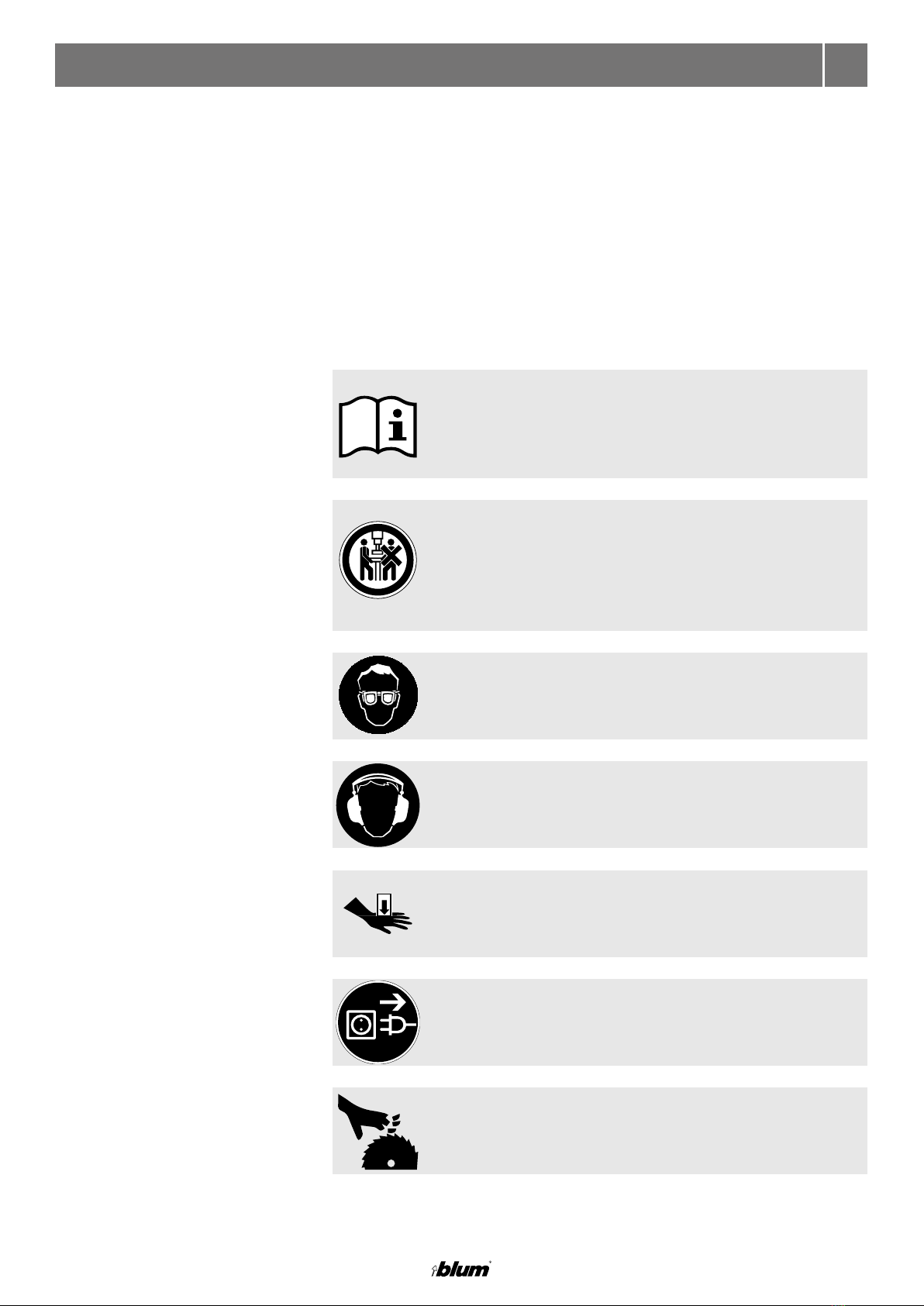
A – Safety ➢Please read the instruction leaflet and the safety information before starting up
the base router.
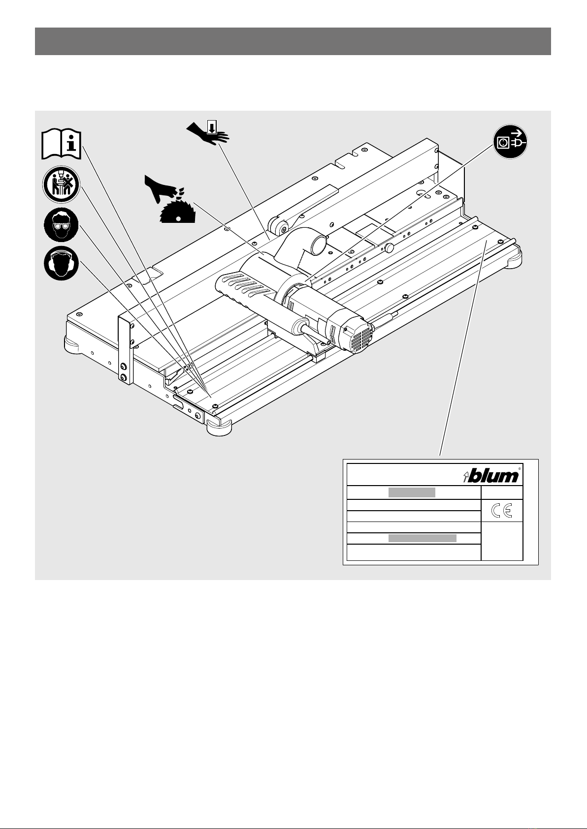
➢We recommend that you use the reference diagram for easier identification of
the parts being described.
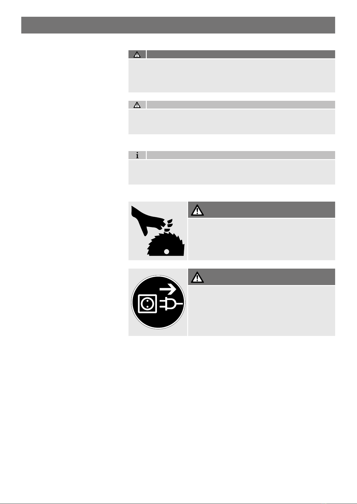
Safety principle
Handling
The base router conforms to current safety standards. Nevertheless, certain risk
factors will remain if the information contained in this instruction leaflet is not
observed.
No solid wood or hard wood or plastic may be processed.
Residual risk according to
DIN ISO EN 12100
■The base router is equipped with all the necessary protection features.
■However, some risk factors will remain for the user, particularly when removing
the protective equipment or when control units fail.
■Other risks are identified by warning signs and safety information. It is therefore
necessary to observe the safety information.
Intended use
Foreseeable misuse
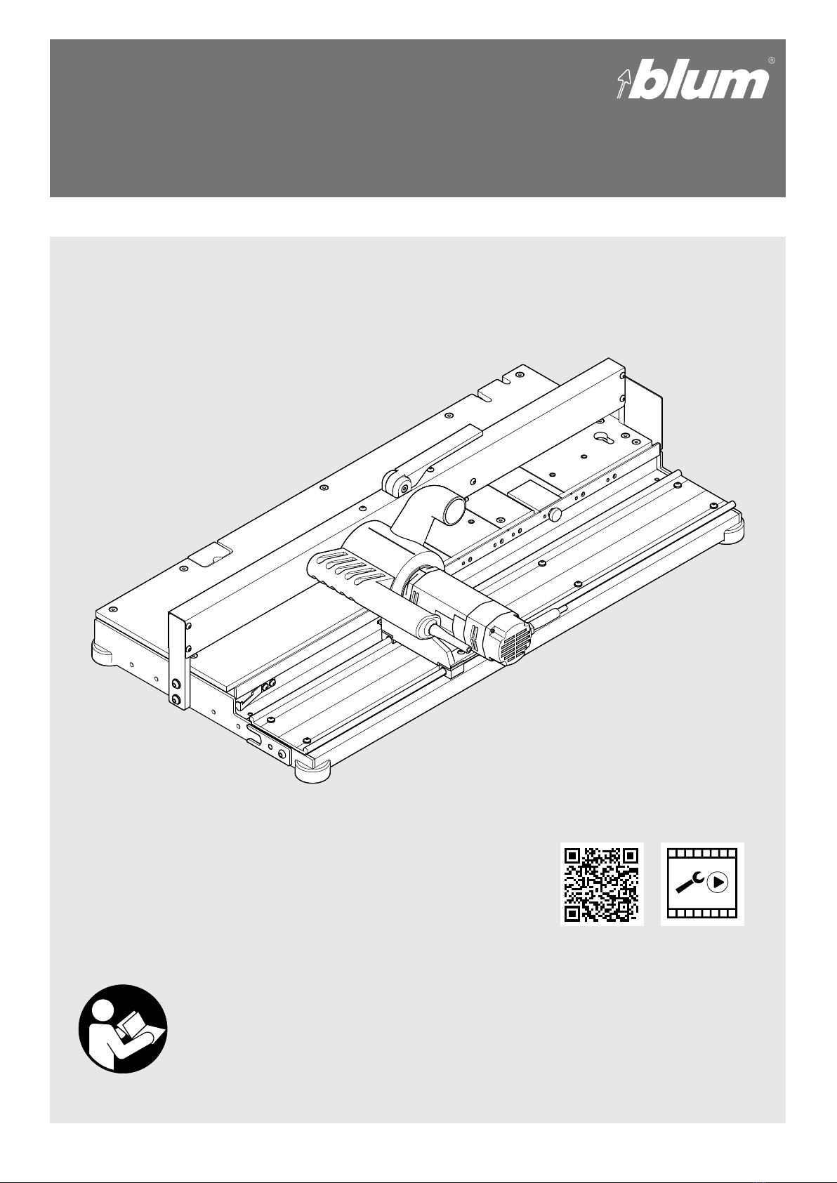
The base router is only intended to process drawer bases for the Blum LEGRABOX
and TANDEMBOX. The base router may only be used under the following conditions:
■The base router may only be operated by fully trained personnel.
■The base router is designed for professional traders.
■Only particle board and medium-density fibreboard (MDF) may be used as
materials.
■The device should only be installed in dry, enclosed rooms.
■Only for drawer bases with a thickness of 15–19 mm. (depending on device type)
■Only original Blum tools may be used.
■No liability can be accepted for any other use.
Responsibilities

4BA-166
M35.7200.XX – Base router
➢The base router is only intended for use by one person.
➢Only attach the base router to a sufficiently stable table.
➢Ensure there is sufficient lighting.
➢Only operate the base router with the extraction system switched on.
➢Before starting work, you should check that the protection devices and
mechanical parts are functioning properly. Any damaged parts should be
replaced by original parts from Blum.
➢Do not make any changes or alterations to the base router.
➢For your own safety, use only those accessories which are recommended or
specified in the instruction leaflet or Blum sales catalogue.
➢Check the electrical cable for damage.
NOTE
■The NOTE sign indicates information that should be observed.
Risk levels WARNING
■WARNING indicates a danger that could lead to serious injury if not avoided.
CAUTION
■CAUTION indicates a danger that could lead to injury if not avoided.
WARNING
WARNING
Serious cuts.
Failure to heed this warning may result in personal
injury.
➢Only push the slide by the handle.
Serious cuts.
Failure to heed this warning may result in personal
injury.
➢The base router must be disconnected from the power
supply before set-up, cleaning and maintenance.

5
EN
➢Ensure that the average air velocity for the extraction system is
at least 20 m/sec.
➢The negative pressure in the extraction system must be 250–300 mbar.
➢Failure to observe the instructions and warnings given for this base router may
result in serious injury.
➢The instruction leaflet should be accessible at all times.
Keep non-authorised persons
away from the base router.
No more than one person may use the base router at a time.
Always wear eye protection when operating this machine.
Danger of crushing!
The base router must be disconnected from the power supply
before cleaning and maintenance.
Serious cuts.
Wear proper ear protection when operating this machine.
Before connecting the base router to the power supply, you must
ensure that you have understood ALL the safety instructions,
warning signs and the instruction leaflet.
Warning signs

6BA-166
M35.7200.XX – Base router
Position of warning signs
Ser.No.: MB 00001
Ref.No.: M35.XXXX.XX
Julius Blum GmbH - A - 6973
Bodenfalzgerät
63.9 lbs
29 kg /
Industriestrasse 1

7
1
2
3
S1
4
8
5
9
12
6
7
10
13
11
14
EN
B – Reference diagrams
Shaft holder
Runner
Slide
Fixing board (delivered loose)
Work top
Clamping lever
Support
Depending on device type
not part of the scope of delivery.
Part number: M35.ZD19
Extraction socket
Support stop
Depth stop
Timber stop
Clamping plate
Stop bar
Transportation lock
Cutter DM 44
11
3
6
12
13
14
8
7
9
10
2
4
5S1
1

8BA-166
22
21
23
24
14
20
M35.7200.XX – Base router
Reference diagram for slide
Sliding film
Flange surface
Notch cutter
Spacer sleeve
Cutter DM 44
Rocker switch
21
20
24
22
23
14

9
8
20
8
EN
Operating elements
Clamping lever
Press down the clamping lever [8] to secure the workpiece.
Rocker switch
The rocker switch [20] is used to switch the base router off and on.
Non-stop operation is not possible.
In the event of overheating due to overload, the motor will be switched off by the
temperature monitoring. After a cooling phase the motor can be operated again.
8
20

10 BA-166
M35.7200.XX – Base router
Dimensions and weight
Requirements for the work area
H:
W:
D:
C – Set-up and start-up
Height (H): _________________________________________________________ 250 mm
Width (W): __________________________________________________________ 580 mm
Depth (D): __________________________________________________________ 990 mm
Weight: _______________________________________________________________ 29 kg
➢Only use in dry, enclosed rooms.
➢Ensure there is sufficient lighting.
➢A table height of more than 900 mm is recommended.
➢The specified width, depth and height are minimum dimensions.
➢The base router must only be used on a stable work top.
WARNING
The base router weighs 29kg.
Failure to observe this information may result in personal injury.
➢The base router must be lifted by two persons.
kg
> 750 mm
> 560 mm
> 900 mm

11
EN
Fixed attachment to worktop
The base router must be securely connected to the workbench.
Failure to heed this warning may result in personal injury and material
damage.
The following fixing methods are intended for the base router:
- fixed attachment to the work top
- removable attachment to the worktop
WARNING
➢Screw the base router to the work top.
Removable attachment to worktop
➢Measure the depth X of the workbench.
Requirement:
Table depth X at least 750 mm.
X

12 BA-166
M35.7200.XX – Base router
➢Position the fixing board [1] within the table length
and screw to the frame.
➢Secure the base router to the work top with fixing boards [1] and screw clamps.
Removing the transportation lock
➢Remove the transportation lock [11].
The slide of the base router is secured for transport.
X
1
11

13
EN
Connecting the power supply ➢Insert the plug.
The base router is designed for 230–240 V 50/60 Hz.
NOTE
■The outlet must be fitted with a PE protective contact.
■The outlet must have a 16 A fuse.
■After finishing work, disconnect the base router from the power supply.
■Avoid overloading the outlet.
■Do not use the base router together with an extension lead or cable drum.
■Use a separately protected outlet for the extraction system and base router.
Connecting the extraction system
➢Insert an extraction hose with an inner diameter of 50 mm into the extraction
socket [9] and secure it.Extraction socket [9] outer diameter 50 mm.
➢Ensure that the average air velocity for the extraction system
is at least 20 m/sec.
➢The negative pressure must be 250–300 mbar.
➢Move the slide [S1] across the full length.
Check that the cable and hose can move freely.
Avoid tensioning or scraping the cable and hose.
9
S1

14 BA-166
M35.7200.XX – Base router
D – Information about milling
Milling with depth stop [6]
for uncoated workpieces
Milling with timber stop [7]
for coated workpieces
The depth stop [6] is used to position the workpiece.
For workpieces with edge bands and for backs, we recommend using
the timber stop [7].
The timber stop [7] prevents torn edges and edge bands. When processing backs,
the use of the timber stop [7] is strongly recommended.
The timber stop [7] is designed for small processing quantities and must therefore
frequently be replaced.
■The timber stop [7] is included loose.
■Spare part – part number: M35.ZT01 (10 pieces)
NOTE
6
7

15
EN
Timber stop drawing [7]
■For in-house production, the timber stop [7] must be pre-notched.
This will significantly improve the result of the processed workpiece.
NOTE
Replacing the timber stop [7]
The timber stop [7] becomes worn through frequent milling. This can lead to torn
edges on the workpiece. To avoid this, the timber stop [7] must be reworked, if
necessary.
7

16 BA-166
M35.7200.XX – Base router
➢Shorten the timber stop [7] by 32 mm.
➢Reposition the timber stop [7] using the next through-hole.
➢The timber stop [7] can be reworked twice.
7
7

17
EN
With the additional slide [S2], edges and edge bands are milled from the rear.
When working with the additional slide, an additional work process is required:
Work process 1: Mill the workpiece at the rear using the additional slide [S2].
Work process 2: Cut through the workpiece with the front slide [S1].
This processing method completely avoids torn edges.
Milling with additional slide [S2]
(optional – part number:
M35.ZS0M01 SCHLITT)
■The additional slide [S2] may not be included in the standard scope
of delivery, depending on the device type.
■Part number: M35.ZS0M01 SCHLITT
NOTE
S2
S1
S2

18 BA-166
M35.7200.XX – Base router
Panel thickness
E – Processable products, required accessories, work steps
LEGRABOX
Notch
Drawer base [30] Cutter fittings
Selecting Set-up
■The cutter M35.ZF44.03 should not be used in the processing of panel thicknesses up to 16 mm.
The spacer sleeve [24] must be mounted in place of the cutter.
■For the product TANDEMBOX, no further processing is necessary for panel thicknesses up to 16 mm.
NOTE
In scope of delivery
16
38
8
37
24

19
EN
M35.0035.01 M35.ZT01
Support [5]Timber stop [7]Depth stop [6]
Set-up Processing
Clamp workpiece
Mill workpiece
25 25 25
26
29
6
7

20 BA-166
M35.7200.XX – Base router
M35.ZD19
M35.ZD19
M35.ZD19
M35.ZD19
Depending on device type not part of the scope of delivery
Panel thickness
LEGRABOXTANDEMBOX
Notch
Notch
Back [31]
Back [31]
Drawer base [30]
Drawer base [30]
Cutter fittings
Cutter fittings
Stop bar [13]
Stop bar [13]
Selecting
Selecting
Set-up
Set-up
For restrictions for Blum products with panel thickness
greater than 16 and up to 19 mm – see page 46:
19.5
16
19.5
16
19.5
16
16
3819.5
8
37
37
37
37
22
22
22
14
14
14
14 13
13
13
This manual suits for next models
1
Table of contents