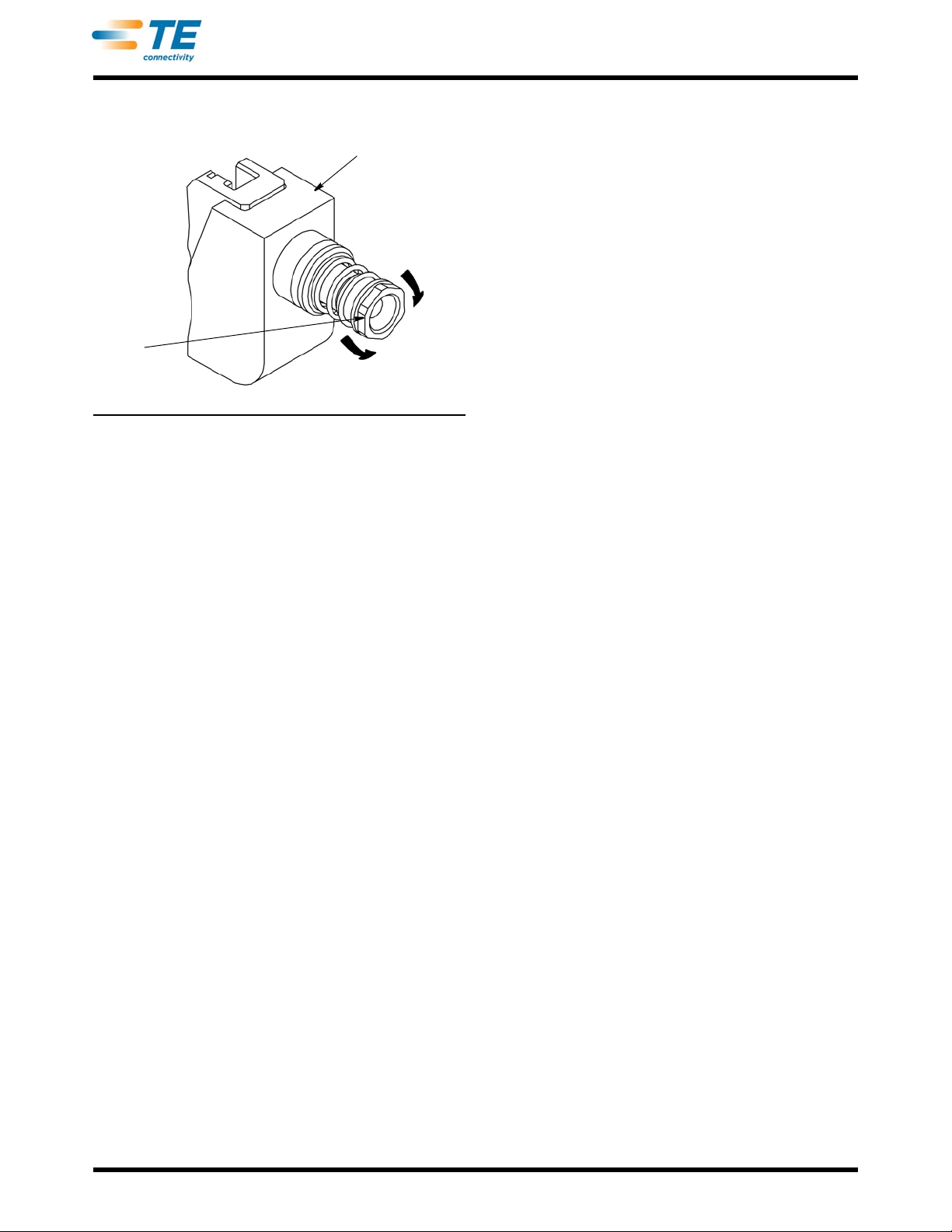
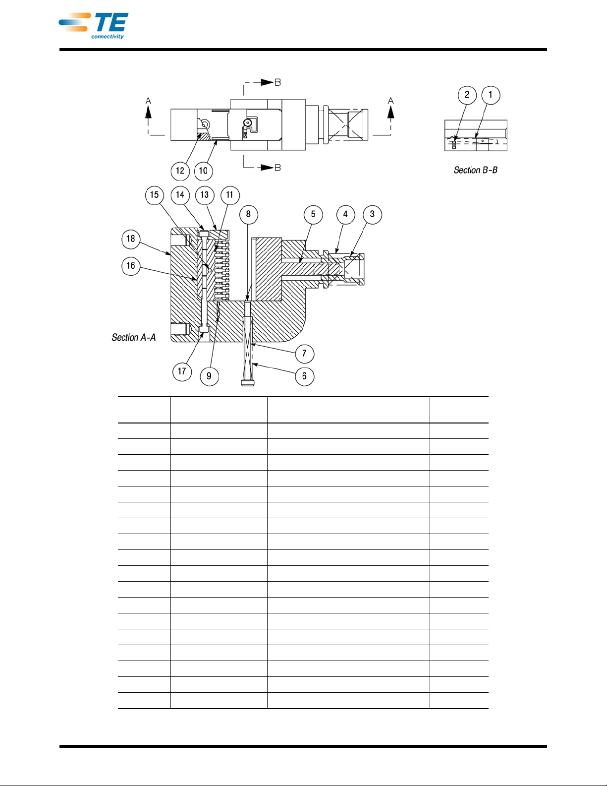
TE Connectivity 58644-1 User manual

Ram
Insertion Rod Adjuster
Push Rod
Locating Pawl (Hidden)
Wire Inserter
Wire Guide
©2011 Tyco Electronics Corporation, a TE Connectivity Ltd. Company
All Rights Reserved
*Trademark
TE Connectivity, TE connectivity (logo), and TE (logo) are trademarks. Other logos, product and/or Company names may be trademarks of their respective owners.
1of 5
Instruction Sheet
TOOLING ASSISTANCE CENTER
1-800-722-1111
PRODUCT INFORMATION
1-800-522-6752
This controlled document is subject to change.
For latest revision and Regional Customer Service,
visit our website at www.te.com
LOC B
408-4406
Mass Insertion Terminating Head 58644-1
for MTA (Mass Termination Assembly) 100
Feed-Through Receptacle Connectors 28 OCT 11 Rev C
Figure 1
1. INTRODUCTION
Mass Insertion Terminating Head 58644-1, shown in
Figure 1, is designed to terminate MTA 100 feed-
through receptacle connectors (positions 2 through
12) onto discrete wire sizes 28 through 22 AWG with a
maximum insulation diameter of 1.27 mm [.050 in.].
Refer to Figure 2 for reference connector part
numbers.
NOTE
i
This head is designed to terminate one connector
at a time.
NOTE
i
A complete list of current connector part numbers
cannotbemaintainedonthisdocument.Forallpart
numbers and their description, refer to Catalog
82056 or contact Product Information at the
number at the bottom of this page.
The head is used with Pistol Grip Manual Handle
Assembly 58074-1. For terminating head installation
procedures, and setup and operation of the handle
assembly, refer to Instruction Sheet 408-6790. Read
this and the referenced material before terminating
any connectors.
NOTE
i
Dimensions on this sheet are in metric units [with
U.S. customary units in brackets]. Figures are not
drawn to scale.
Reasons for reissue are provided in Section 8,
REVISION SUMMARY.
2. DESCRIPTION (Figure 1)
The terminating head, when properly installed onto the
handle assembly, serves as a guide for the connector
during termination.
Features of the head and their functions are as
follows:
Wire Inserter-supports each wire in individual wire
slots so that, during the insertion cycle, the wire forced
into the two-slotted beam of the contact.
Wire Guide-holds the wires in position over the wire
inserter.
Ram-locates and holds the connector while pushing it
down onto the wires.
Locating Pawl-holds connector in proper alignment to
the wire inserter.
Push Rod-used to push the terminated connector past
the locating pawl for removal.
Insertion Rod Adjuster-is a piston for the ram and
regulates the travel of the inserted wires.

WIRE SIZE
(AWG)
MTA 100 FEED-THROUGH RECEPTACLE CONNECTORS
(With Locking Ramp)■
COLOR CODE WITH POLARIZING TABS WITHOUT POLARIZING TABS
22 Red 644540 640620
24 White 644563 640621
26 Blue 644564 640622
28 Green 644565 640623
■Dash numbers indicate number of contact positions (-2 through -12 are applicable for this terminating head).
408-4406
2of 5
Rev C
Figure 2
Each wire is terminated in a connector contact using
the insulation displacement technique (a terminating
technique which inserts unstripped wire into a slotted
contact beam to form a reliable electrical connection
between the wire and the contact). Contact
termination is complete when the handle assembly is
actuated.
3. SETUP
3.1. Installing Head
The head can be installed onto the handle assembly
and used as a hand-held tool, or several tools can be
mounted onto a board to be used as a low-level
harness board fixture.
The board must have two 6.36-mm [.250-in.] holes
spaced 44.45 mm [1.75 in.] apart for each head.
Secure each head with screws. See Figure 3.
NOTE
i
NOTE
i
Thehandle assembly is not quickto install ontothe
head; therefore, each head should have its own
handle assembly.
3.2. Test Termination
At least one test termination should be performed and
inspected before starting production. Determine the
wire size and select the appropriate color-coded
connector.
1. Using a small knife, cut off the wire retainers
(strain relief) from both sides of the test connector.
See Figure 4.
NOTE
i
Wire retainers must be removed from test
connectorstoprovideaclearviewforinspection-do
NOT use test connectors for production
applications.
2. Terminate the test connector according to Section
4and inspect the connector following the
requirements in Step 6. Make any insertion depth
adjustments to the terminating head according to
Section 5 before starting production.
Handle
Assembly
(Ref)
Installing Head As
Harness Board Fixture
Figure 3
4. TERMINATING PROCEDURE
1. Starting with the wire slot closest to the head
frame, push one wire into one slot for each contact
position of the connector being terminated. See
Figure 5.
2. Insert the connector into the ram with the contact
insulation barrels facing the wire slots.
3. Using a screwdriver (or equivalent), push the
connector into the ram until the connector touches
the surface of the frame. Refer to Figure 5.
NOTE
i
To ensure proper alignment in the head, all
connector positions must touch the surface of the
head frame.

Terminated Test Connector
Wire Retainers Removed
(Both Sides)
Contact Partially
Removed for
Inspection
Lead-In
Transition
No Deformation of
Contact Beam
No Cuts
in Wire
Terminated Production Connector
Contact Slot
408-4406
3of 5
Rev C
Figure 4
Wire Inserted into Wire Slot
Ram
Handle Assembly
Surface of Head
Frame (Connector
Must Start Here)
Figure 5
4. Actuate the handle assembly according to the
instructions packaged with the handle assembly.
CAUTION
!
Aftertheramcompletesthestroke,nowiresshould
be left in the wire slots. If any wires are still in the
slots, pull them up and out of the slots before
continuing.
5. Depress the push rod to move the terminated
connector beyond the locating pawl in the ram.
6. Then grip the wires on both sides of the
connector and carefully guide the connector out of
the ram.
7. Refer to Figure 4 and visually inspect the
connector according to the following. If wire
insertion depth is found to be improper, refer to
Section 5 for head adjustments.
CAUTION
!
Wire insulation tends to return to form after being
compressed. It is important to inspect the
connector within five minutes of termination;
otherwise, an improper inspection may result.
•Conductors are terminated past the lead-in
transition and halfway into the contact slot.
•Wires are not bottomed in contact slots.
•Wire insulation is not nicked or cut in any areas
except in the contact slots.
•Contact beams are not deformed. If damage is
evident, replace the damaged contact according to
the instructions packaged with the connector.
•Wire extends below the connector wire retainers.
NOTE
i
For detailed inspection information, refer to
Application Specification 114-1019.
5. INSERTION DEPTH ADJUSTMENT
The terminating head is preset for nominal wire
insertion depth; however, it may be necessary to make
adjustments to the head, due to the wide range of
cable sizes used, as follows:
1. Remove the head from the handle assembly.

Head Removed from
Handle Assembly
Insertion
Rod
Adjuster
Clockwise to
Decrease
Wire Insertion Depth
Counterclockwise
to Increase
408-4406
4of 5
Rev C
Figure 6
2. If the wires are too deep in the contact slots, turn
the insertion rod adjuster clockwise. A 1/6-
revolution will decrease the wire insertion depth by
approximately 0.20 mm [.008 in.]. If the wires are
not deep enough in the contact slots, turn the
adjuster counterclockwise. A 1/6-revolution will
increase the wire insertion depth by approximately
0.20 mm [.008 in.]. See Figure 6.
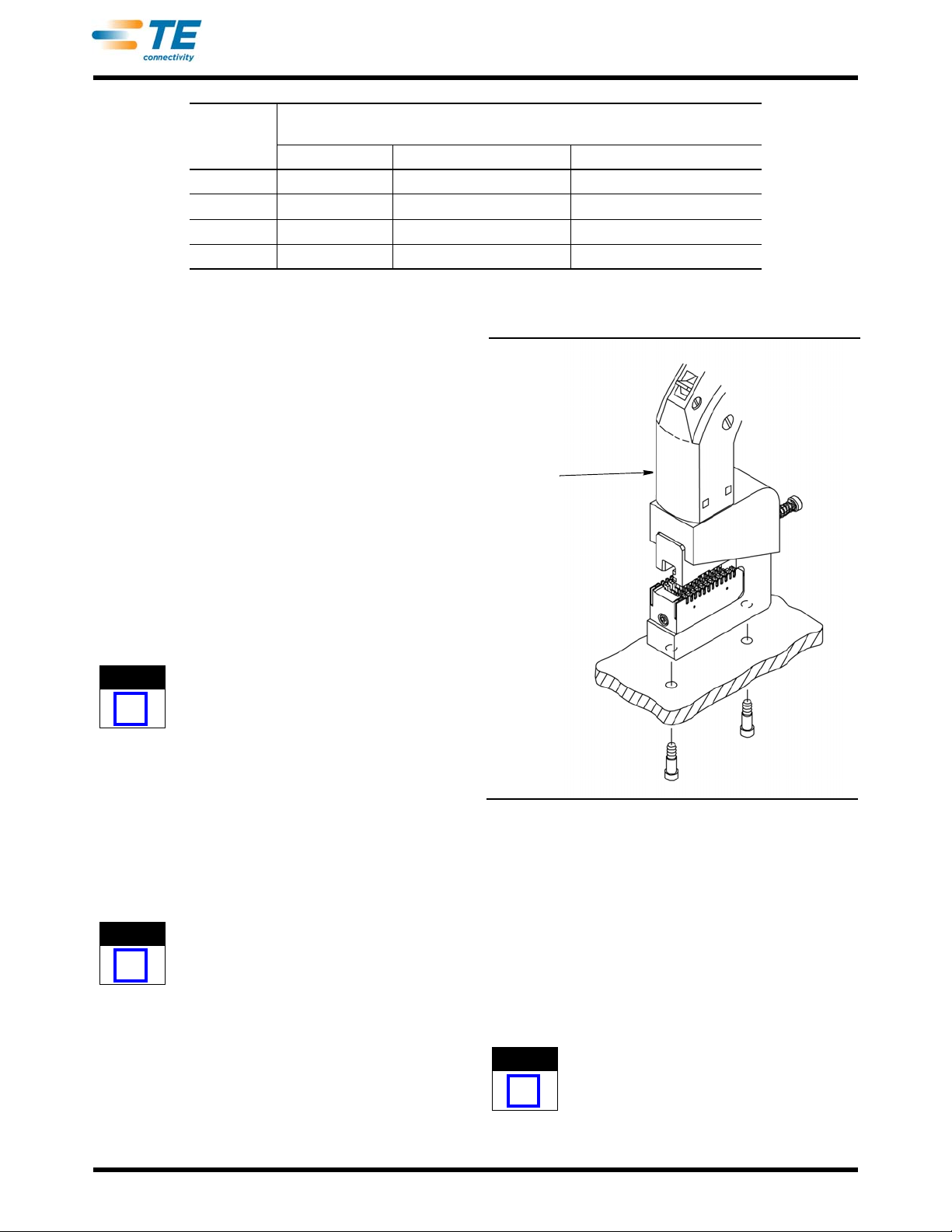
3. Install the head onto the handle assembly; then
terminate and inspect a test connector.
4. Repeat the adjustment as necessary until proper
wire insertion depth is obtained. DO NOT use a
tighter setting than required.
6. MAINTENANCE AND INSPECTION
TE recommends that a maintenance and inspection
program be performed periodically to ensure
dependable and uniform terminations.
6.1. Daily Maintenance
1. Remove dust, moisture, and other contaminants
with a clean, soft brush or a soft, lint-free cloth. Do
NOT use objects that could damage the head.
2. Make sure that all pins, rings, and other
components are in place and secure.
3. When head is not in use, store it in a clean, dry
area.
6.2. Periodic Inspection
Regular inspections should be performed by quality
control personnel. Though recommendations call for
at least one inspection a month, the frequency should
be based on amount of use, working conditions,
operator training and skill, and your established
company policies.
1. Remove all lubrication and accumulated film by
immersing the head in a suitable commercial
degreaser that will not affect paint or plastic.
2. Make certain all components are in place. If
replacements are necessary, refer to Section 7.
3. Check all bearing surfaces for wear. Replace
worn or damaged parts.
4. Inspect the head for flattened, chipped, or broken
surfaces. Replace worn or damaged parts.
7. REPLACEMENT AND REPAIR
Replacement parts are listed in Figure 7. A complete
inventory can be stocked and controlled to prevent lost
time when replacement of parts is necessary. Order
replacement parts through your TE representative, or
call 1-800-526-5142, or send a facsimile of your
purchase order to 1-717-986-7605, or write to:
CUSTOMER SERVICE (038-035)
TYCO ELECTRONICS CORPORATION
PO BOX 3608
HARRISBURG PA 17105-3608
For customer repair service, call 1-800-526-5136.
8. REVISION SUMMARY
Revisions to this instruction sheet include:
•Changed company name and logo

ITEM TE PART NUMBER DESCRIPTION QTY PER
ASSY
1904092-1 PAWL, Locating 1
223147-3 SPRING, Compression 1
3312149-1 ADJUSTER, Rod Insertion 1
422488-5 SPRING, Compression 1
5904087-1 RAM 1
62-22279-5 SPRING, Compression 1
7904093-1 ROD, Push 1
821003-1 SCREW, Flat Head Cap, 0-80 x .12 1
91-23147-2 SPRING, Compression 2
10 904086-1 CLAMP, Wire Guide 2
11 21949-1 PIN, Spiral Wrapped 5
12 904129-1 BLOCK, Wire 2
13 904085-1 GUIDE, Wire 1
14 1-21000-4 SCREW, Socket Head Cap, 4-40 x .38 1
15 21028-2 PIN, Slotted Spring 1
16 904084-1 BLOCK, Inserter 1
17 1-21000-7 SCREW, Socket Head Cap, 4-40 x .75 1
18 904083-1 HEAD 1
408-4406
5of 5
Rev C
Figure 7
Table of contents
Other TE Connectivity Power Tools Accessories manuals
Popular Power Tools Accessories manuals by other brands

Meler
Meler Arion Installation & technical guide

Echo
Echo Speed-Feed Universal 400 LH/RH Installation and loading instructions

Atlas Copco
Atlas Copco BBD 46WS-6 Safety and operating instructions

sauter
sauter OFL1.0 manual

Spearhead
Spearhead Trisaw Series Operator's instruction manual

AEG
AEG OMNI-RT Original instructions