BM PRO BatteryPlus35-II Series User manual

TEAMBMPRO.COM
BatteryPlus35-II
BatteryPlus35-II-HA
BatteryPlus35-II-SI
BatteryPlus35-II-SR
OWNER’S MANUAL


TEAM
BMPRO
.COM
POWERING YOUR ADVENTURES
With over 50 years’ experience in power
solutions combined with manufacturing
and design facilities in Melbourne,
Australia, BMPRO are the leading
experts in RV power management.
Inspired by the great outdoors, we
have created a range of rugged, smart
and reliable products to power your
adventures.
Our range of battery, power and RV
management and control systems gives
you peace of mind when you are on the
road, so that you can relax in even the
most far-flung destinations, knowing
you have control over your power
needs.
To learn more about the BMPRO range
of products, please visit our website
teambmpro.com

SAFETY PRECAUTIONS
Please read the Safety Precautions before installing or using the BatteryPlus35-II.
Be sure to observe all precautions without fail. Failure to observe these instructions
properly may result in personal damage, or personal injury which depending on the
circumstances may be serious and cause loss of life.
Copyright © 2020
MANUAL PART 035011
REV 3.0
Designed by BMPRO, one of Australia’s leading power solution experts, the BMPRO range of
products are proudly Australian-Made in Melbourne, Victoria and represent a high-quality
product that will provide years of service.
DISCLAIMER: BMPRO accepts no liability for any loss or damage which may occur from
the improper or unsafe use of its products. Warranty is only valid if the unit has not been
modified or misused by the customer.
4
WARNING
Ensure that there is a good ventilation from the battery area.
Correct installation is the most critical factor in ensuring the safe use of the
BatteryPlus35-II. If every consideration of these instructions has been satisfied, the
BatteryPlus35-II will be safe to operate.
This product is not intended for use by persons (including children) with reduced
physical, sensory or mental capabilities, or lack of experience and knowledge, unless
they have been given supervision or instructions concerning the use of the appliance
by a person responsible for their safety.
Children shall not play with this product. Cleaning and user maintenance should not
be performed by unsupervised children.
Ensure that the product is well ventilated and that if the product has a fan, the fan is
not covered or obstructed.
Metal conducts electricity. Take care not to drop or touch metal objects onto the
battery terminals, which if contacts the battery terminals, could cause short circuits
and may lead to serious personal injury. Take care and remove unwanted metal
objects from the vicinity of battery and BatteryPlus35-II. Remove any personal
metal adornment such as chain, watch or ring before handling the battery and
BatteryPlus35-II.
Do not attempt to charge non-rechargeable batteries. Charging a non-rechargeable
battery may result in the battery catching fire or possible explosion
Do not replace a damaged mains power cord. If the power cord is damaged, the
product must be discarded.
Batteries are always electrically live and must be treated with extreme caution. They
can supply high short circuit currents, even if they appear damaged or undamaged.
Before servicing a battery, disconnect the power supply from all power sources.
Only charge battery types which are supported by this charger (see “Compatible
Battery Types”)
Do not allow water or other liquids to enter the power supply area.
Do not drop or vigorously shake the product as this may cause damage. Do not shock
the product, its accessories or batteries as this may cause the product or battery to
fail, catch fire or explode.
Stay away from magnetic equipment. Radiation may erase the information stored on
this product causing it to become inoperative.
Please note that your battery can only reach top performance level only after it has
been fully charged and discharged two or three times.
5

6

CONTENTS
SAFETY PRECAUTIONS 4
ABOUT THE BATTERYPLUS35-II 8
WHAT’S INCLUDED 8
OPTIONAL ADD-ONS 8
COMPATIBLE BATTERY TYPES 9
DESCRIPTION OF PARTS 10
INSTALLATION INSTRUCTIONS 13
PERSONNEL 13
EARTHING 13
VENTILATION, ORIENTATION AND THERMAL CONSIDERATIONS 14
MOUNTING 15
MAINS CABLE 15
REPLACING BATTERIES 16
USING YOUR BATTERYPLUS35-II 18
INPUT POWER SOURCES 18
BATTERY CHARGING AND MANAGEMENT WITH THE BATTERYPLUS35-II 20
ECO MODE 21
STORAGE MODE 21
USING THE BATTERYPLUS35-II AS A POWER SUPPLY
(BATTERYLESS OPERATION) 22
FAULT PROTECTION 22
SERVICING, MAINTENANCE AND STORAGE 23
FAQS AND TROUBLESHOOTING 24
BATTERY 24
CARAVAN LOADS 24
SOLAR 25
APPENDICES 26
BATTERYPLUS35-II OPERATIONAL STATUS INDICATOR 26
BATTERY CHARGING MANAGEMENT ALGORITHM 27
SPECIFICATIONS 29
WARRANTY TERMS AND CONDITIONS 30
7

ABOUT THE BATTERYPLUS35-II
BMPRO’s BatteryPlus35-II is a battery management system designed specifically
for use in recreational vehicles. The BatteryPlus35-II operates from 100 to 240V
AC mains power supply, towing vehicle auxiliary and solar panel to provide 35A of
current to simultaneously power caravan loads and charge the caravan battery.
The BatteryPlus35-II is available in a range of models to suite any RV and battery
management needs.
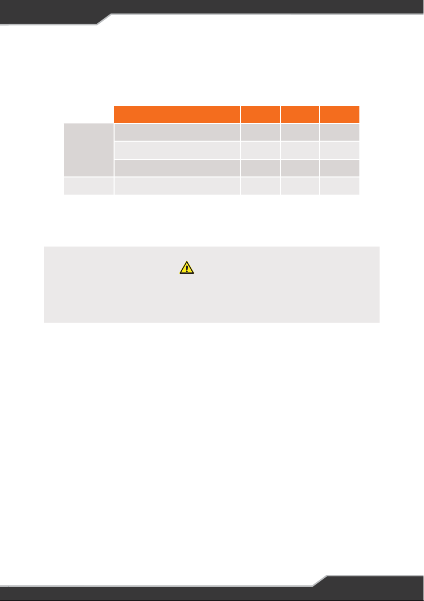
FEATURE BP35-II-SI BP35-II-SR BP35-II-HA
In-built Solar 20A - PWM 30A - MPPT 30A - MPPT
Solar Connection Direct to BatteryPlus35-II
Lithium (LiFePO4) Charging No No Yes
Maximum AC Charging Current 20A 20A 30A
WHAT’S INCLUDED
Included with this product are:
9BatteryPlus35-II Battery Management System
9BatteryPlus35-II Owner’s Manual
OPTIONAL ADD-ONS
To get the most of your BatteryPlus35-II it may be used with the following products
(sold separately) from the BMPRO range:
BC300 + CommLink External Shunt for integration of additional accessories and high
current loads such as inverters
RVView Battery Monitor to monitor battery parameters and charge sources
Trek Battery Monitor to gain greater insights into battery usage, the ability to monitor
water tank levels and control water pumps
Odyssey + OdysseyLink to monitor battery usage and caravan features
(tanks and temperature) and control caravan loads from an in-built monitor
MiniBoost DC-to-DC charge-booster for RV applications
Table 1: Comparison of features for the models of the BatteryPlus35-II range
8
COMPATIBLE BATTERY TYPES
The BatteryPlus35-II is rated to charge battery banks of up to 600Ah in capacity and
of the following battery types:
BATTERY SI SR HA*
Lead Acid
Valve-Regulated (VRLA) Yes Yes Yes
Absorbed Glass Mat (AGM) Yes Yes Yes
Gel Yes Yes Yes
Lithium LiFePO4 No No Yes
Table 2: Batteries compatible for use with the BatteryPlus35-II
* By default, the BP35-II-HA is configured to charge lead acid batteries.
WARNING
The BP35-II-HA is designed for use with Lead Acid and LiFePO4
Lithium batteries only. Do not connect other types of Lithium batteries
to the BP35-II-HA. BMPRO Invicta batteries are recommended.
9

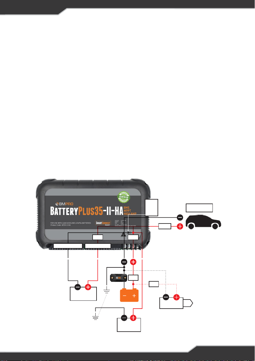
DESCRIPTION OF PARTS
1. MAINS CABLE
The BatteryPlus35-II is pre-cabled with a permanent mains power supply cord
for use with 240V or 110V input power.
2. LOAD TERMINAL BLOCK – COMMON NEGATIVE CONNECTION
Negative wire connection return point for the caravan’s 12V loads.
3. LOAD OUTPUTS – 15A X 2 POSITIVE CONNECTIONS
Used for connecting the positive wire of the 12 V loads, outputs 1 & 2
4. LOAD OUTPUTS – 10A X 12 POSITVE CONNECTIONS
Used for connecting the positive wire of the 12 V loads, outputs 3 – 14
5. AUX+
Connection point for external DC input positive.
WARNING
Do not replace a damaged power supply cord. If the power cord is
damaged, the BatteryPlus35-II must be discarded. Ensure that the
AC mains source always has an earth terminal.
Figure 1: BatteryPlus35-II. Compatible for all models
10

6. BATT+
Connection point for battery positive and negative terminal.
Attach fuse to Batt+ wiring
7. BATT-
8. NOT USED
9. RESET (MASTER RESET BUTTON)
Press the Master Reset Button if any part of the system is
unresponsive or not operating correctly during or after installation
10. CAN BUS COMMUNITCATION CONNECTOR
To connect to and power BMPRO accessories (BC300 + CommLink
External Shunt or OdysseyLink) or monitors (RVView or Trek).
11. REMOTE SWITCH TERMINAL BLOCK (RSW)
Terminal block for connecting an optional remote switch. This switch
is used to disconnect the loads from all power
12. MOUNTING HOLE (X4)
13. LOAD OUTPUT STATUS INDICATORS
14. SOLAR PANEL CONNECTION
This connection is for the solar panel input
LED COLOUR LOAD OPERATIONAL STATUS
GREEN Loads operating normally
RED Fault with load
OFF Load is off
Table 3: LED Status Indicators
11

15. +BRK BATTERY OUTPUT (40A RATED)
WARNING
Loads connected to +BRK output will not turn off even during ECO mode or
Storage mode. To maintain good health of the battery during low voltage, manually
turn these loads off. Exceeding 40A total load current may turn-off some of the load
outputs 1-14. All loads connected on this output must be individually fused.
This output is an uncontrolled 15th output with a maximum current rating of 40 A.
This is specifically designed for loads which do not need to be isolated or have a
current rating of higher than the inbuilt circuit protection of the individual outputs
and have a current rating less than 40 A. This may include but not limited to:
• BMPRO SwayControl
• BMPRO Trailsafe (+)
• Heaters
• Stereo memory
16. SYSTEM STATUS INDICATOR
Indicates the operational status of the BatteryPlus35-II
WARNING
When braking systems are already connected to the +BRK
output, then non-braking loads must use a separate output.
12
INSTALLATION INSTRUCTIONS
PERSONNEL
Installation is to be carried out only by suitably qualified personnel.
EARTHING
As the BP35-11 is positive sensing for current monitoring, this allows for chassis
earthing of both the battery and the negative of DC 12 V appliances.
Note: All DC 12 V positive cables must be wired to outputs 1-14 or the 40A battery
output connection.
Loads greater than 15A
For DC 12V appliances that may draw greater than 15A, such as inverters, both
positive and negative must be wired direct to the new Battery negative on the BC300
(See Figure 2) to ensure that the current is seen by the BP35-II and the correct
information displayed, particular State of Charge & Time Remaining.
Refer to our website for more information on this product
https://teambmpro.com/products/bc300-commlink-external-shunt/
Figure 2: Wiring Diagram
AC
Auxiliary
Inverter
TrailSafe,
Misc loads
Lights,
Pump etc
Rsen
Switch
Fuse
Fuse
Fuse
Negative Output Positive Output
Internal
MosFET
body
diode
13
VENTILATION, ORIENTATION AND THERMAL CONSIDERATIONS
The preferred orientation is with the load connection at the bottom, as shown in
figure 2: Recommended mounting holes and located such that there is a minimum
of 80 mm free air space from all vented sides of BatteryPlus35-II. This allows for the
lowest operating temperature of the internal electronics and the highest reliability of
the product.
The final enclosure must provide adequate ventilation to the outside world (or larger
internal cavity) to prevent excessive heating of the air within the enclosure.
At normal room temperature (25°C), the unit is rated to provide full power in both
vertical and horizontal orientations. At elevated temperature up to 50°C, the output
current is de-rated to 32A.
WARNING
The enclosure air temperature can easily exceed
50°C if adequate ventilation is not provided.
WARNING
Do not install BatteryPlus35-II in the same compartment
where flammable material such as petrol or LPG is stored.
The BatteryPlus35-II has over-temperature protection and will shut down if its
internal temperature rises above safe level. The BatteryPlus35-II will automatically
restart once it has cooled to an acceptable level.
14

WARNING
If the supply cord is damaged, it must not be
replaced and the appliance should be scrapped.
MOUNTING
BatteryPlus35-II should be securely mounted to a suitably rigid surface, using four
pre-drilled mounting holes. Dimensions are provided in Figure 3: Mounting Diagram.
MAINS CABLE
This is pre-cabled and fitted with a mains plug. Ensure that the connections to the
mains supply is in accordance with the national wiring rules, and that the earth
connection is installed, see Mounting Diagram, Figure 3. The mains cable must be
at least 80mm away from the output cables. All DC connections should be wired
according to Figure 2: Wiring diagram.
The plug must be accessible during installation. If this is not possible, an accessible
mains disconnection switch must be incorporated in the mains wiring where the plug
is connected.
Figure 3: Mounting Diagram
15

WARNING
Sparks have the potential to cause an explosion if combustible gases are present.
The following procedures are designed to minimise the risk of spark generation
while connecting or disconnecting the battery. The positive terminal of the battery
MUST NOT be connected to the chassis.
Figure 4: Wiring the battery to the
BatteryPlus35-II.
To protect against short-circuits and
reversed battery connections, install
a 40A fuse, as close as possible to the
battery’s positive terminal.
WARNING
Do not install battery in the same compartment
where flammable material, such as petrol, is stored.
WARNING
Before using a battery other than that which was installed at the caravan
dealership, consult with the battery manufacturer for a detailed description of the
installation, uses and maintenance of the battery. Verify that the type and capacity
of the battery or batteries used are compatible for use with the BatteryPlus35-II.
Figure 4 details connection of the caravan battery to the BatteryPlus35-II.
After fitting a new battery to the BatteryPlus35-II, make sure that it is configured in
your battery monitor.
Correctly configuring the battery capacity and profile will ensure that the
BatteryPlus35-II will select the best charging parameters for the caravan battery in
use, and the software accurately estimates battery usage.
REPLACING BATTERIES
16

Disconnecting a Battery from the BatteryPlus35-II
1. Power off all loads connected to the BatteryPlus35-II, the easiest way is with the
switch connected to the BatteryPlus35-II’s RSW input
2. Turn off and remove all power sources (auxiliary/mains/solar) to the
BatteryPlus35-II
3. Disconnect the battery’s negative (black) terminal from the BatteryPlus35-II
Batt- Connection Point
4. Disconnect the battery’s positive (red) terminal from the BatteryPlus35-II Batt+
Connection point
Connecting a Battery to the BatteryPlus35-II
1. Power off all loads connected to the BatteryPlus35-II, the easiest way is with the
switch connected to the BatteryPlus35-II’s RSW input
2. Turn off and remove all power sources (auxiliary/mains/solar) to the
BatteryPlus35-II
3. Connect the battery’s positive (red) terminal to the BatteryPlus35-II Batt+
connection point
4. Connect the battery’s negative (black) terminal to the BatteryPlus35-II Batt-
connection point
Connecting Multiple Batteries
Before connecting multiple batteries in parallel to the BatteryPlus35-II, check that
all batteries are same
• manufacturer
• model
• capacity
• age, and
• fully charged
Figure 5 shows the recommended wiring for connecting multiple batteries
in parallel to the BatteryPlus35-II. Depending on system requirements, a qualified
auto-electrician may wire the batteries differently.
Figure 5: Recommended wiring to
connect multiple batteries in parallel
17

USING YOUR BATTERYPLUS35-II
INPUT POWER SOURCES
The BatteryPlus35-II can charge from auxiliary, mains and solar input sources.
When multiple inputs are available to the BatteryPlus35-II, the BatteryPlus35-II
uses power as specified in the tables below to provide the current to simultaneously
power caravan loads and charge the caravan battery.
Table 4: Input Power Sources to the BP35-II-SI, BP35-II-HA and BP35-II-SR
INPUT SOURCE TO BATTERYPLUS35-II POWER SOURCE
AUX + Mains Mains
AUX + Solar AUX/Solar Blending
AUX + Mains + Solar Mains
Mains + Solar Mains
18

Auxiliary
To prevent your car battery from discharging when the vehicle’s ignition is off, please
ensure the auxiliary is wired so that it is automatically disconnected in this condition
WARNING
The auxiliary input is designed for use with 12V DC power sources. The voltage of the
DC power source connected to the auxiliary input must not exceed 14.8V.
Fuse protection is required at the auxiliary’s positive input and to protect the wiring
from the source. The rating on this protective fuse must not exceed 30A.
Mains
The BatteryPlus35-II mains power cord can accept power from either a 100 to 240V
50/60Hz voltage outlet.
Solar Input on the BatteryPlus35-II-SI
The BP35-II-SI features an in-built PWM charger. This enables solar panels
to be connected directly to the BatteryPlus35-II-SI without the need for an
external regulator.
The PWM charger supports the use of standard 12V solar panels up to a total
of 20 A / 300W 450W.
WARNING
Ensure solar panel Open Circuit Voltage (Voc) does not exceed
26V and Short Circuit Current (Isc) rating does not exceed 20A.
WARNING
Ensure solar panel Open Circuit Voltage (Voc) does not exceed 26V
Solar Input on the BP35-HA and the BP35-SR
The BP35-II-HA and the BP35-II-SR both feature an in-built MPPT charger. This
enables solar panels to be connected directly to the BatteryPlus35-II-HA or
BatteryPlus35-II-SR without the need for an external regulator.
The MPPT charger supports the use of standard 12V solar panels up to a total of 30 A
19

BATTERY CHARGING AND MANAGEMENT WITH THE BATTERYPLUS35-II
The BatteryPlus35-II can deliver up to 35A to simultaneously power loads and charge
the caravan battery, with a maximum charging current of 20A for the BP35-II-SI and
BP35-II-SR and 30A for the BP35-II-HA with the difference being reserved to supply
12 V loads.
The maximum charging current will be reduced if the loads present are drawing
significant current and as the battery approaches full charge. To ensure that the
caravan battery is charged by the maximum charging current, switch off non-
essential loads.
Auxiliary Charging
When charging from auxiliary, the BatteryPlus35-II monitors the battery voltage
level and charges as needed. Auxiliary charging is commenced only when the
auxiliary voltage exceeds the battery voltage by at least 0.5V and is greater than
12.6V.
Mains Charging
When charging the battery from mains, the BatteryPlus35-II applies a multi-stage
charging algorithm. Further details can be found in the Appendices.
Solar Charging with the BatteryPlus35-II-SI
When charging the battery from solar, the BP35-II-SI applies a multi-stage charging
algorithm.
The BatteryPlus35-II (SI) will use solar as a charging source if the voltage generated
by the solar panel is greater than the battery voltage.
Solar Charging with the BatteryPlus35-II-HA and BatteryPlus35-II-SR
When charging the battery from solar, the BP35-II-HA and BP35-II-SR applies a
multi-stage charging algorithm.
The BatteryPlus35-II (HA and SR) will use solar as a charging source if the voltage
generated by the solar panel is greater than 17.5V for at least two minutes.
WARNING
Do not attempt to charge non-rechargeable batteries. Charging a non-
rechargeable battery may result in the battery catching fire or possible explosion.
20
Other manuals for BatteryPlus35-II Series
2
This manual suits for next models
3
Table of contents
Other BM PRO Batteries Pack manuals


