VOLTIUM ENERGY VE-ESS-R5120 User manual

0
Rechargeable Lithium Battery
Operation and Maintenance manual
VE-ESS-R5120
Version: V-02

Advanced battery for residential application 2
0
Legal Provisions
This manual describes in detail the requirements and procedures for safe installation and
operation of VOLTIUM ENERGY lithium battery pack. Please read this manual carefully, only
qualified persons are allowed to install, operate and maintain the system, otherwise it may cause
product damage or personal safety risks.
Any actions against safety operation, or do not follow rules of this manual and limited warranty
letter, will void warranty and qualification of this product. Meanwhile, the manufacturer will be not
responsible for the product damage, property damage, personal injury or even death.
The information contained in this manual is accurate when it’s issued. VOLTIUM ENERGY reserve
right to change specification (such as optimization, upgrade or other operations) without prior notice,
please always view the latest document via QR code. In addition, please noted that the
diagrams/schematics in this document are used to help understand system configuration and
installation instructions, which may be different from the actual items at the installation.
Legal Terms
Voltium Energy will retain the copyright of this document, do not extract, copy or translate in any ways without the written
permission.

Advanced battery for residential application 3
0
Content
1. Information ..............................................................................................................................................4
1.1 Validity..............................................................................................................................................4
1.2 Target Group...................................................................................................................................4
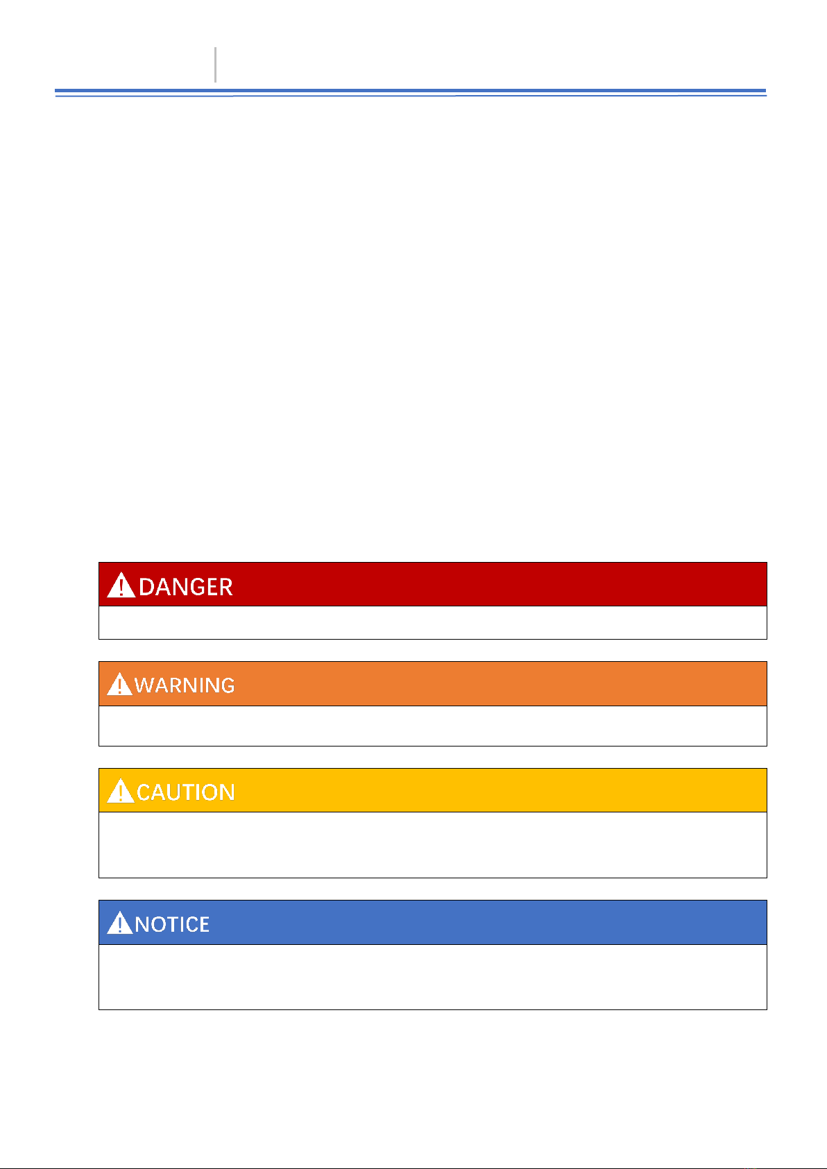
1.3 Levels of warning messages........................................................................................................4
1.4 Symbol Description........................................................................................................................ 5
1.5 Abbreviation Description ...............................................................................................................5
2. Safety ........................................................................................................................................................ 7
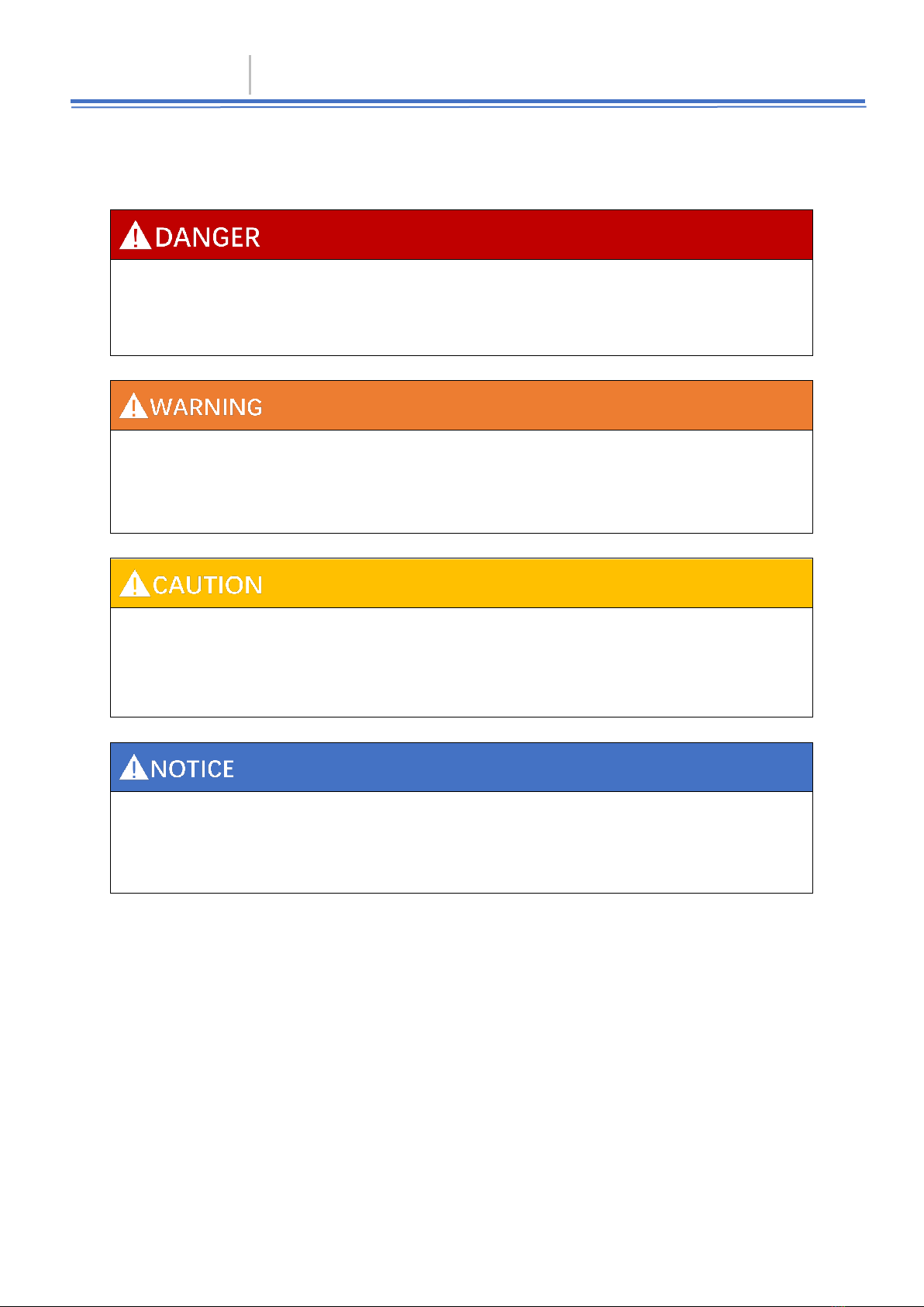
2.1 Safety precautions .........................................................................................................................7
2.2 Safety instructions..........................................................................................................................7
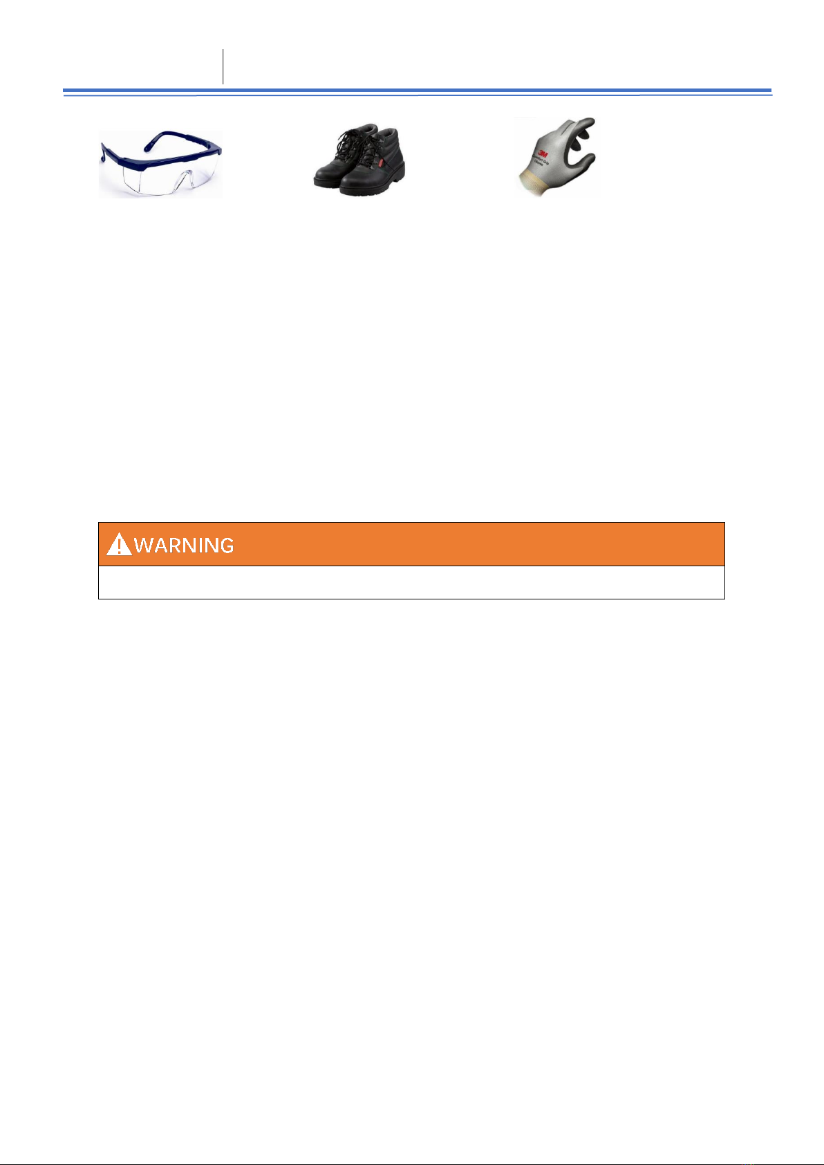
2.2.1 Safety gear ..........................................................................................................................7
2.2.2 Emergency safety measures ............................................................................................8
2.2.3 Other Tips ............................................................................................................................8
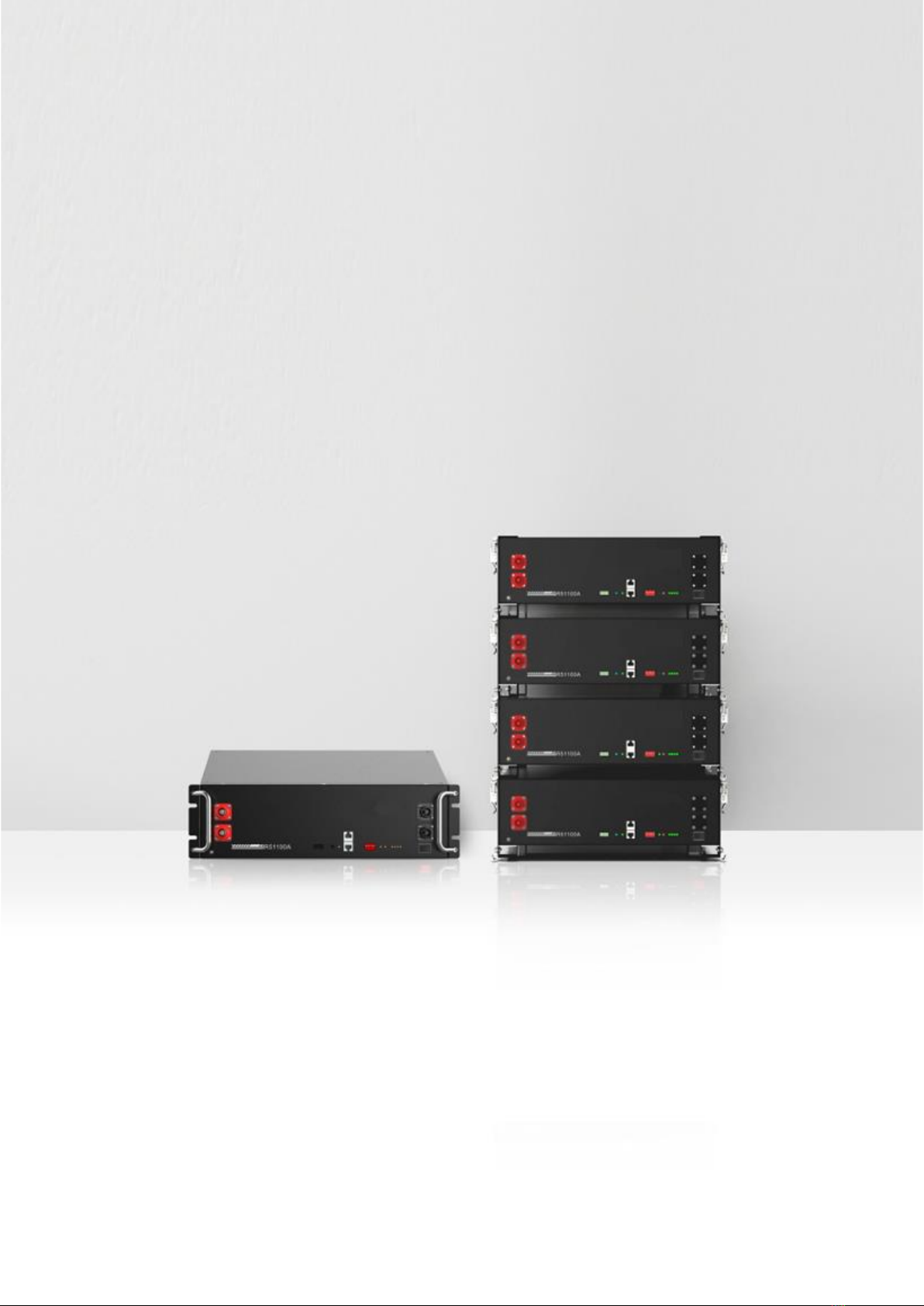
3. Product Overview ..................................................................................................................................9
3.1 Introduction .....................................................................................................................................9
3.2 Features ..........................................................................................................................................9
3.3 Specification..................................................................................................................................10
3.3.1 Dimension..........................................................................................................................10
3.3.2 Parameters ........................................................................................................................10
3.3.3 Panel Interface.................................................................................................................. 11
3.4 Protection function .......................................................................................................................14
4 Installation ..............................................................................................................................................16
4.1 Preparation....................................................................................................................................16
4.1.1 Safety Compliance ...........................................................................................................16
4.1.2 Environment ......................................................................................................................16
4.1.3 Tools.................................................................................................................................... 16
4.2 Inspection......................................................................................................................................17
4.2.1 Unpacking..........................................................................................................................17
4.2.2 Scope of delivery ..............................................................................................................17
4.2.3 External cable kits.............................................................................................................20
4.2.4 Battery registration ...........................................................................................................21
4.3 Start Installation............................................................................................................................21
4.3.1 Remainder .........................................................................................................................21
4.3.2 Procedures ........................................................................................................................21
4.3.3 Tips......................................................................................................................................24
5. Cable connection and commissioning........................................................................................... 26
5.1 Get battery ready .........................................................................................................................26
5.2 Grounding cable connection.......................................................................................................26
5.3 Communication cable connection .............................................................................................26
5.4 DC power cable connection .......................................................................................................27
5.5 Connecting with inverter .............................................................................................................27
5.6 Commissioning.............................................................................................................................30
5.7 Switch off battery..........................................................................................................................31
6. Transport, Storage............................................................................................................................... 33
7. Disposal of battery .............................................................................................................................. 33
Appendix I ..................................................................................................................................................33

0
1. Information
1.1 Validity
This document is valid for: VE-ESS-R5120 Battery Pack.
1.2 Target Group
This document is intended for qualified persons and operators. Only qualified persons are allowed to perform the
activities marked in this document with a warning symbol and the caption "Qualified person". Qualified persons
must have the following skills:
⚫Knowledge of how lithium iron phosphate batteries work and are operated.
⚫Knowledge of how an energy storage system (including PV/battery/hybrid inverter, MPPT, Meter, Distribution box
etc.) works and is operated.
⚫Knowledge of local applicable connection requirements, standards, and directives.
⚫Training in the installation and commissioning of electrical devices, batteries.
⚫Training in how to deal with the dangers and risks associated with installing, repairing and using electrical devices,
batteries.
1.3 Levels of warning messages
The following levels of warning messages may occur when handling the product
Indicates a hazardous situation which, if not avoided, will result in death or serious injury.
Indicates a hazardous situation which, if not avoided, could result in death or serious injury.
Indicates a hazardous situation which, if not avoided, could result in minor or moderate injury or product permanent
damage.
Indicates a situation which, if not avoided, can result in property damage or product not work or accelerated product
damage

Advanced battery for residential application 5
0
1.4 Symbol Description
1.4.1 Symbols on products label
Label
Definition
Beware of electrical shock
Do not place the battery within
children/pet touchable area.
Do not place the battery near
heat source and flammable
material
Do not expose the battery to
direct sunlight, rain and snow.
Do not short circuit the battery
Lable
Definition
The certificate label for Safety by
TÜV Rheinland
The UL1973 certificate label for
Safety by Intertek
The certificate label for
European EMC directives
The certificate label for U.K EMC
directives
Recycle label
WEEE designation
1.4.1 Other symbols
Label
Definition
Indicates activities that can only be performed by qualified persons
Grounding point
VOLTIUM ENERGY trademark of NRG Europe battery.
1.5 Abbreviation Description
Abbreviation
Definition
Battery/battery
pack/battery module
Single VE-ESS-R5120 rechargeable lithium iron phosphate battery pack including
cells, BMS and enclosure etc.
Battery system/cluster
Multiple VE-ESS-R5120 battery pack connected in parallel with power,
communication and grounding cables and installation auxiliaries.
BMS
Battery management system. Electronical Unit to ensure lithium cells’ safety and
display information or control the battery work mode.

Advanced battery for residential application 6
0
SOC
State of charge. The battery state of charge refers to the percentage of the remaining
capacity and rated capacity of the battery.
SOH
State of health. The battery health status refers to the percentage between the full
charged capacity and the rated capacity of the battery.
DIP switch
Dual in-line package switch
COCP
Charge over current protection
DOCP
Discharge over current protection
COVP
Cell over voltage protection
POVP
Pack over voltage protection
CHTP
Charge high temperature protection
DHTP
Discharge high temperature protection
CUVP
Cell under voltage protection
PUVP
Pack under voltage protection
CLTP
Charge high temperature protection
DLTP
Discharge high temperature protection
SCP
Short circuit protection

Advanced battery for residential application 7
0
2. Safety
2.1 Safety precautions
Explosion risk
Do not impact the battery with heavy objects.
Do not squeeze or pierce the battery pack.
Do not throw the battery pack into the fire.
Fire risk
Do not expose the battery pack to the condition over 80°C.
Do not put the battery near a heat source, such as a fireplace.
Do not expose the battery pack to direct sunlight or raining.
Electric shock risk
Do not allow non-qualified person to disassemble the battery pack.
Do not touch the battery pack with wet hands.
Do not expose the battery pack to moisture or liquid environment.
Damage risk
Do not short-circuit or reverse connect the battery.
Do not use chargers or charging devices unapproved by the manufacturer to charge the battery.
Do not mix batteries from different manufacturers or different kinds, types or brands.
2.2 Safety instructions
The battery has been designed and tested in accordance with international (such as UL, IEC, UN38.3 etc.) safety
requirements. However, due to various factors during the whole lifetime process, VOLTIUM ENERGY cannot
guarantee absolute safety, in order to prevent personal injury and property damage and ensure long-term operation
of the battery, please do read the below section carefully to operate the battery and handle emergency situations.
2.2.1 Safety gear
It is required to wear the following safety gear when installing and handling the battery pack.

Advanced battery for residential application 8
0
Safety Glasses Safety Shoes Insulated gloves
2.2.2 Emergency safety measures
Water invasion
Please cut off the AC power supply of the system first and then disconnect all switched under the premise of
ensuring safety.
Electrolyte or gas leakage
If the battery pack leaks electrolyte, avoid contact with the leaking liquid or gas. If one is exposed to the leaked
substance, immediately perform the actions described below.
Gas Inhalation: Evacuate the people in the contaminated area and seek medical aid immediately.
Eye Contact: Flush your eye with clean and flowing water for 15 min, and seek medical aid immediately.
Skin Contact: Thoroughly rinse the exposed area with soap and water to be sure no chemical or soap is left on
them, and seek medical aid immediately.
Ingestion: Induce vomiting, and seek medical help immediately.
In case of fire situations, please use carbon dioxide fire extinguisher rather than liquid to put out fires.
2.2.3 Other Tips
All the product are strictly inspected before shipment, please contact your supplier for replacement if you notice
there’s any defectives such as swelling.
Do not disassemble batteries and components, otherwise the manufacturer will not be responsible for any damage
caused by unauthorized disassembly or repair.
Do enable the battery to be safely grounded before use to make sure the system in safe and normal operation.
Please ensure that the electric parameters of these devices are compatible mutually before connecting the battery
to other devices.
Please take the environmental factors into careful considerations to ensure that the system can work in a suitable
condition as the environment and storage methods have a certain impact on the service life and reliability of this
product.

Advanced battery for residential application 9
0
3. Product Overview
3.1 Introduction
The VE-ESS-R5120 battery is designed for residential application and works as a storage unit in the photovoltaic
system. It is a 51.2V lithium battery system, with BMS inside. It could be operated in both on-grid, back-up and off-
grid modes with compatible inverters. Below is the general schematic of an ac-coupled system with the batteries.
This electrical connection in this diagram is only for illustration, please follow the Manual suggestions of related
devices and operate in accordance with locally applicable connection requirements, standards, and directives.
3.2 Features
Highest safety, battery is made from LiFePO4 chemistry and comply with highest international safety and transport
standard.
Modular and flexible, support up to 32 batteries connect together to expand the system energy.
Build-in pre-charge circuit to avoid rush current when connecting with different inverter/chargers.
Automatic dynamic addressing function when connected multiple batteries together.
Support a maximum of 96% DOD under off-grid and back-up application.
Built in BMS provide warning and protection functions including over-discharged, over-charged, over-current,
short-circuit and high/low temperature.
LiFePO4 as cathode material and automatic balancing function to meet longer cycle life.
Compact size and light weight for easy installation and maintenance.
Multiple installation bracket to adopt with different customers’ requirement.
LED display, CAN/RS485 port for external communication and upgrade the BMS firmware.
Rapid shut down function for North American market.

Advanced battery for residential application 10
0
3.3 Specification
3.3.1 Dimension
3.3.2 Parameters
Items
VE-ESS-R5120
Rated voltage
51.2V
Max. voltage range
44.8~57.6V, Shipping voltage>51.2V
Charge voltage
56.0V
Float charge voltage
54.6V
Nominal [email protected]
5.12KWh
Usable [email protected]
4.92kWh
Nominal [email protected]
100Ah
Dimension
482*133.5*460mm (18.9*5.2*18.1 inch)
Weight
~46kg (101lb)
Standard charge current
≤50A
Max. charge current
70A
Standard discharge current
≤50A
Max. discharge current
100A (initial temp. ≤30℃)
Peak discharge current
101~119A@5mins | 120~200A@15S
Communication
RS485 /CAN
Max parallel number
32 pcs
Operation temperature 1
Charge: -5~50℃
Discharge:-10~50℃
Storage temperature
@off mode
0℃<T<30℃
<6 months
-10℃<T<45℃
<3 months
Recommended environment
15~35℃, 5~75%RH

Advanced battery for residential application 11
0
The optimum operating temperature range is from 15°C to 30°C, Frequent exposure to the harsh temperatures
may worsen the performance of the battery pack and cycle life.
3.3.3 Panel Interface
No.
Items
Usage description
Remark
A
Handles
For handling, intallation and disasembly of battery
B
Grounding
Used to connect battery with ground
C
Positive terminal
Used to connect the inverter/charger
D
Dry contact
1 channel input signal
2 channels output signal
E
Reset
Used to reset BMS or sleep/awake BMS in power
on mode.
F
M/S
Used to indicate the module is Master or Slave
battery
Single mode:OFF
Parallel mode:
ON- Master battery
OFF-Slave battery
G
Link IN
Link OUT
For internal and external communication
H
DIP
Used to set the RS485 baud rate and inverter
protocol choosing
I
RUN
Used to show battery is in running status when
lighting or flashing
J
ALM
Used to show battery Alarm/Protection status
K
SOC
Used to show battery real-time SOC
L
Power switch
Used to Power on/off battery

Advanced battery for residential application 12
0
M
Negtive terminal
Used to connect the inverter/charger
N
Mounting ear
Used to fix with rack or cabinet
3.3.3.1 D: Dry contact
PIN
Type
1
NO Output1, Charge enable/disable signal
2
3
NO Output2, discharge enable/disable signal
4
5
Passive INPUT signal.
Rapid Shut Down function for US
6
3.3.3.2 G: Link IN / Link OUT
Port
Pin No.
Definition
Remarks
Link IN
1
RS485-B1
1.Used to connect with external
devices to establish
communication.
2.Used to connect with upper
battery pack Link OUT.
2
RS485-A1
3
SGND
4
CAN-H
5
CAN-L
6
SGND
7
RS485-A1
8
RS485-B1
Link OUT
1
RS485-B2
Used to connect with
downward battery pack Link IN.
2
RS485-A2
3
SGND
4
CAN-H
5
CAN-L
6
SGND
7
RS485-A2
8
RS485-B2
3.3.3.3: DIP addressing
DIP
Remarks
RS485 baud rate
Undefined
Protocol
1
2
3
4
5
6
7
ON: 115200
Reserved for multiple cluster
parallel and other future function
0
0
Protocol ID0
OFF: 9600
1
0
Protocol ID1
0
1
Protocol ID2
1
1
reserved
Keep all batteries
the same setting
Keep default setting
Master: according to inverter brand
Slave: keep default setting
Note:
Only master battery needs to set the Protocol ID, keep all slave battery default setting, after choose the protocol

Advanced battery for residential application 13
0
ID, the battery will auto detect the inverter infomation and corresponding to get into running, restart to take effect
after setting new DIP sequence.
Protocol ID
CANbus Connection
RS485 Connection
DIP setting
(Master battery)
0
Victron/SMA/Studer Innotec/Sofar
Voltronic/RCT/MPP/Alpha
outback/Phocos
X000000
1
Sol-Ark/Solis/Goodwe/Deye/
Growatt/SAJ/LUXPOWER
Megarevo/INVT/Sermatec/
TBB/MUST/Sunsynk
X000010
2
Schneider
X000001
Fail to follow the DIP switch setting will cause the communication fault between battery and inverter, for more detail
setting with different inverter/charger, please contact your supplier for consultation.
3.3.3.4RUN/ALM/SOC
Mode
Status
RUN
ALM
LED indicator
Description
●
●
●
●
●
●
Power off
-
OFF
OFF
OFF
OFF
OFF
OFF
All OFF
Standby
Normal
FLASH1
OFF
According to battery SOC
See note
Warning
FLASH1
FLASH3
Charge
Normal
ON
OFF
According to battery SOC
(highest SOC LED: FLASH2)
See note
Warning
ON
FLASH3
COCP
FLASH1
OFF
According to battery SOC
Stop charging
Discharge
Normal
FLASH3
OFF
According to battery SOC
See note
Warning
FLASH3
FLASH3
CUVP/PUVP
OFF
FLASH3
OFF
OFF
OFF
OFF
Stop discharging
DOCP
OFF
ON
OFF
OFF
OFF
OFF
Stop discharging
Temperature
CHTP/DHTP
CLTP/DLTP
OFF
ON
OFF
OFF
OFF
OFF
Stop
charging/dischargin
g

Advanced battery for residential application 14
0
Failure
Cell/NTC
failure
Sensor
failure
MOS failure
Reversed
polarity /SCP
OFF
ON
OFF
OFF
OFF
OFF
Stop
charging/dischargin
g
Note: ‘Warning’ including items of cell imbalanced/low voltage/high current/high&low temperature.
FLASH Type
ON
OFF
FLASH1
0.25S
3.75S
FLASH2
0.5S
0.5S
FLASH3
0.5S
1.5S
3.4 Protection function
Items
Description
Remark
Charge end
COVP
POVP
The BMS will stop charging if any cell or PACK voltage
reach the protection value and it will be auto-released
only when both Pack and cell voltage back to the release
voltage range or there is efficient discharge current.
Can Automatic recovery.
Discharge end
CUVP
PUVP
The BMS will stop discharging if any cell or PACK voltage
is under the protection value and it will be released only
when all the cell voltage back to the release voltage
range or there is efficient charge current.
Can Automatic recovery. Please
charge timely, otherwise it may be
in low-power mode to be over-
discharged and damage battery.
CHTP
DHTP
The BMS will stop charging or discharging or both if any
cell/environment/MOS temperature is beyond the range.
Automatic recovery when
temperature falls.
CLTP
DLTP
The BMS will stop charging or discharging or both if any
cell/environment/MOS temperature is under the range.
Automatic recovery when
temperature rise.
COCP
The BMS will stop charging when the charging current is
higher than the protection value. And it will release from
the protection when the system delays time is met.
Automatic recovery. If locked after
three consecutive times, manual
intervention is required.
DOCP
The BMS will stop discharging when the discharging
current is higher than the protection value. And it will
release from the protection when the system delays time
is met
Automatic recovery. If locked after
three consecutive times, manual
intervention is required.
SCP
Reversed
polarity
The BMS will stop charging when detect short circuit or
reversed polarity.
Charge to release.
Manual press reset.
Temperature,
Voltage,
Current sensor
failure
Enter the failure mode, manual intervention is required no
charging and discharging.
Manual intervention.
Sleep mode
After reaching a certain condition, BMS will enter
dormancy mode to reduce BMS consumption
Charge, press reset or restart to
activate.

Advanced battery for residential application 15
0
Please re-charge the battery via MPPT, grid/generator or other energy source within 24h if the battery is over
discharged, otherwise, it may be damaged.
Manually short-circuit and reverse the battery will void the warranty.

Advanced battery for residential application 16
0
4 Installation
4.1 Preparation
4.1.1 Safety Compliance
The system installation must be finished by qualified person(s), During the whole installation process, please
strictly follow the local safety regulations and related operating procedures.
4.1.2 Environment
The operating environment shall meet the following requirements:
Category
Description
Working
temperature
-10℃-50℃(Maximum operating range)
15℃-30℃ (Optimal temperature)
Relative humidity
5%~90%, No condensation
Altitude
<3000m
Safety requirement
Do not expose the battery to direct sunlight, rain and snow.
Do not place the battery within children/pet touchable area.
Do not place the battery near heat source and flammable material
Do not drop, deform, impact, cut or spearing with a sharp object.
Do not put heavy things on battery.
Do not disassemble the battery without Manufacturer's permission.
No conductive dust and water or other liquid to contact battery.
Follow the emergency measure if there is water invasion or electrolyte and gas
leakage.
Contact your supplier within 24 hours if any product failure happens.
4.1.3 Tools
Tools
Torque screwdriver
Multi-meter
Flat-head screwdriver
Phillips-head screwdriver
Torque wrench
Cable crimper
Wire stripper
Drill
Wire stripper
Tape measure
Phillips-screwdriver bit
Hex-key bit

Advanced battery for residential application 17
0
4.2 Inspection
4.2.1 Unpacking
Please load and unload it in accordance with the specified requirements to prevent sun and rain when you
receive the equipment.
Please check and confirm the goods (such as quantity, appearance, etc.) according to the "scope of delivery "
before unpacking.
Do light take and put during unpacking process to protect the surface coating of the object;
Please record and feedback to the manufacturer if the inner packing is damaged after unpacking.
4.2.2 Scope of delivery
Check the scope of delivery for completeness and any externally visible damage. Contact your supplier for
supplementary delivery if the listed material is incomplete or damaged.
General materials
(Battery unit)
Battery Pack *1pcs Manual *1pcs Warranty document
*1pcs
Optional materials
(Noted that each pack unit together with one type bracket as default)
Mounted kits
Type
Material detail
Qty.
Rack mounted
kits
(Packing with general
materials, with mark
on the carton)
A: Float nuts M6
6pcs
B: Combination Screw
4pcs
C: Battery to battery parallel positive cable(250mm)
1pcs
D: Battery to battery parallel negetive cable(250mm)
1pcs
WARRANTY
CARD

Advanced battery for residential application 18
0
E: Battery to battery grounding cable(300mm)
1pcs
F: Battery to battery communication cable(250mm)
1pcs
Stack mounted
kits
(Packing using
separately carton)
A: Stacking components
4pcs
B: Head screw M4
16pcs
C: Battery to battery parallel positive cable(250mm)
1pcs
D: Battery to battery parallel negetive cable(250mm)
1pcs
E: Battery to battery grounding cable(300mm)
1pcs
F: Battery to battery communication cable(250mm)
1pcs
Wall mounted
kits
(Packing using
separately carton)
A: External hexagon slotted combination screw
6pcs
B: Cross recessed recessed combination screw
2pcs
C: Battery to battery parallel positive cable
1pcs
D: Battery to battery parallel negetive cable
1pcs

Advanced battery for residential application 19
0
E: Battery to battery grounding cable
1pcs
F:Cross recessed small countersunk head screws
16pcs
G: Expansion bolt M10*60
4pcs
H: Decorative panel
1pcs
I: Wall mounted bracket
1pcs
J: Battery to battery communication cable
1pcs
Floor mounted kits
(Packing using
separately carton)
A: Outer hexagon combination bolt
4pcs
B:Cross recessed small countersunk head screws
12pcs
C: Battery to battery parallel positive cable
1pcs
D: Battery to battery parallel negetive cable
1pcs
E: Battery to battery grounding cable
1pcs
F: Battery to battery communication cable
1pcs
G: Base
1pcs
H:Decorative panel
1pcs

Advanced battery for residential application 20
0
I: Side fixing parts
2pcs
J: Expansion bolt M6*50
6pcs
4.2.3 External cable kits
Cables connected to inverter or junction box belongs to an External Cable kits, NOT include in battery carton.
Customers need buy it separately, the information are as below.
Type
Detail
Qty.
Power cable
1pcs
1pcs
Grounding cable
1pcs
Inverter
communication
cable(1 out of 3)
1pcs
Battery side pin
Inverter side pin
Version I(CAN):
Pin 4
Pin 7
Pin 5
Pin 8
Pin 6
Pin 3
Version II(CAN):
Pin 4
Pin 4
Pin 5
Pin 5
Version III(RS485):
Pin 1
Pin 3
Pin 2
Pin 5
Table of contents