bmcm BP16 User manual

BP16
Backplane for MAL Amplifiers
Measuring Amplifers and Sensors.
Get Connected.
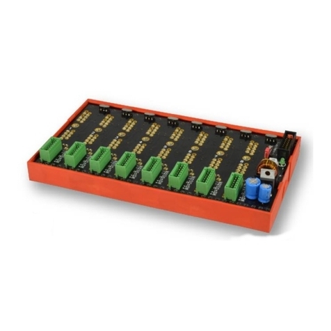
Backplane for miniature amplifiers: Up to 16
measuring amplifiers, converters, or any other
function modules can be integrated in the
BP16. If installed close to the signal, it provides
for high interference resistance. Ideal for
remote signal conditioning of passive sensors.
Signal Conditioning in Miniature
Format.
In type of construction, the cost-effective MAL
modules are designed like a 24-pin DIL IC.
Measurement applications can therefore be
realized even in problematic locations. With
suitable measuring amplifiers, multiple wire
technique can be realized, too.
Optimally Supplied.
The BP16 is operated with 9-30V. The
integrated amplifiers are supplied by the
electrically isolated power supply. In addition,
5V (50mA) with galvanic isolation are provided
for sensor supply.
Signal Connection.
D-Sub Standard.
Sensors or other voltage signals can
comfortably be connected at a 37-pin D-Sub
female.
Connection to the DAQ System.
The amplifier outputs are available at a 37-pin
D-Sub female connector. They are connected
to the input lines of a data acquisition system.
Combining the BP16 with a measuring card or
DAQ system from bmcm makes an extreme
compact measurement system.
External Device.
The BP16 is accommodated in a stable
aluminum housing ideal for mobile use.
Notches in the housing frames allow for fixing
the BP16 to a DAQ system (e.g. USB-AD14f)
providing for a stable measuring unit.
The Smaller Options.
You Have the Choice.
For all needing less channels: The backplane
for miniature amplifiers is also available as a
2-channel version with carrier for DIN rail
mounting (BP2) or integrated in a waterproof
IP65 housing (BP2-BOX).
Functional diagram

Product
BP16-eng.docx Page 2
1 Preparations
1.1 Equipment of the BP16
To equip the BP16 with measuring amplifiers, the device must
be opened. First remove the red housing frames and open the
housing cover by loosening the upper screws at the front and
back side.
Up to 16 miniature measuring amplifiers (e.g. MAL series from
bmcm, see chapter 4.1) can be plugged into any of the 24-pin
sockets on the backplane (see chapter 2.5.1). If the marking of
the socket is on the left, pin 1 is bottom left (see chapter 0).
Check for correct poling when equipping the backplane. Change amplifier
modules only at no load!
1.2 Installation of the BP16
The BP16 is installed as an independent measuring amplifier
system before a PC data acquisition system. If combined
with a DAQ system from bmcm accommodated in an
aluminum case (e.g. LAN-AD16fx, USB-AD14f, USB-
AD16f), the housings of both devices can comfortably be
fixed together at the red frames of the device making a
compact unit. To directly connect the outputs of the BP16
with the inputs of the DAQ system, use the short ribbon
cable included with delivery. The device can be supplied
(see chapter 2.1) via the DC connector (9-30V DC) and a
power supply unit (e.g. ZU-PW10W available as accessory.
2 Connections, Pin Assignments, and Components
The available connections and different components of the BP16 are shown in the following figure of
the board (view on top of the board (fitted with components), connectors on both sides). The
measuring amplifier slots are consecutively numbered from channel 1 = 1 to channel 16 = 16.
Figure 1

BP16
Page 3
2.1 Power Supply (DC)
The BP16 is operated with 9-30V via the 3-pin DIN plug at the back of
the device.
2.2 Analog Inputs
The 16 analog inputs or sensors are connected at the 37-pin
D-Sub IN female on the back of the BP16. To realize cold-
junction compensation for thermocouple measurement with
MAL-THR, a temperature sensor can be connected at pin 18
(e.g. option ZU-TR available as accessory, see chapter 4.2). In
addition, 5V sensor supply is provided at pin 17.
The following table and figure on the right show the pin
assignment of the 37-pin input connector:
2.3 Analog Outputs
The 16 analog outputs are connected at the 37-pin D-Sub
OUT female on the front of the BP16.
They are the outputs of the respective measuring amplifiers or
of the bypassed DIL sockets (see chapter 2.5.1), which are
connected to the analog inputs of the DAQ system.
The following table and figure on the right show the pin
assignment of the 37-pin output connector:
Pin
Function
1(+), 20(-)
Analog In 1
2(+), 21(-)
Analog In 2
…
…
16(+), 35(-)
Analog In 16
17
+5V for sensor supply
18
temperature reference input (for MAL-THR)
19
-
36, 37
analog ground (AGND) for sensor supply
Pin
Function
1..16
Analog Out 1..16
20..35
analog ground (AGND) for outputs
17, 18, 19, 36, 37
-

BP16
Page 4
2.4 Pin Assignment of the Amplifier Slots
Each channel of the backplane can be equipped with miniature
amplifiers of the MAL series from bmcm (see chapter 4.1) or compatible
measuring amplifiers of other manufacturers. That means that all inputs
can be adjusted to the most different signals and sensors.
See the relevant data sheet about how to use the individual measuring
amplifier. The figure on the right shows view on top of the module
backplane (marking of the socket on the left).
Pin
Name
Function
Pin
Name
Function
1, 2
n. c.
-
13, 14, 15
n. c.
-
3
+EX
pos. sensor supply
16
-UB
neg. supply (-9V)
4
LO
neg. signal input
17, 18, 19, 20, 21
n. c.
-
5
HI
pos. signal input
22
OUT
amplifier output ±5V
6
-EX
neg. sensor supply
23
TR
temp. reference (only MAL-THR)
7, 8, 9, 10
n. c.
-
24
+UB
pos. supply (+9V)
11
GND
power supply ground
12
n. c.
-
2.5 Using the Jumpers
Each of the 16 amplifier slots is provided with two (uneven slot) or
four jumpers (even slot).
The jumpers are numbered corresponding to the number of their DIL
slot (see chapter 2.5.1 and 2.5.2). Jumpers of one slot have different
functions and are distinguished from each other by an additional
letter (e.g. slot 2: J2, J2b, J2c, J2d).
The following table gives a short overview of the jumper function
(default setting marked in red):
Do not use a measuring amplifier at a slot with a closed jumper.
The pin connectors are very damageable. In case of contact problems replace them if necessary.
Always only close either jumpers Jx, Jxc or Jxb, Jxd. Never close all 4 jumpers at the same time!
•
Uneven slot:
•
Even slot:
Jumper
Function
Jumper
Function
J1
bypass +IN of slot 1
J2
bypass +IN of slot 2
-
-
J2b
lead through +EX of slot 1 to 37-pin D-Sub IN connector
J1c
bypass -IN of slot 1
J2c
bypass -IN of slot 2
-
-
J2d
lead through -EX of slot 1 to 37-pin D-Sub IN connector
…
…
…
…

BP16
Page 5
2.5.1 Bypassing a Free Slot
If slot x (x=1..16) is not equipped with a measuring amplifier, as the input is open or only voltages are
to be measured, this socket has to be bypassed by closing jumpers Jx and Jxc. In this case, this
input cannot be operated differentially. Ex works all sockets are bypassed (see chapter 2.5).
2.5.2 Making Excitation Pins Available
If using long cables, 4-wire technique, or for precise measurements, we recommend to lead the
excitation connections of the measuring amplifiers through to the 37-pin D-Sub IN female to avoid
interferences.
At the D-Sub 37 IN connector, the excitation of a channel (uneven slot) can be reached at the pins
that used to be the connections for the following even analog input (see chapter 2.2, e.g. +EX1 to pin
2, before: +IN2; -EX1 to pin 21, before: –IN2) which is not available anymore in this case.
Leading the excitation through is achieved by closing jumpers Jxb and Jxd located at the DIL slots
with even numbering (see chapter 2.5). Mixed use of 2- and 4-wire technique is also possible (see
chapter 3.3).
The following table shows the pin assignment of the D-Sub 37 IN female connector if all excitation
connections are used:
Pin
Function
1(+), 20(-)
Analog In 1
2(+), 21(-)
excitation voltage for Analog In 1
3(+), 22(-)
Analog In 3
4(+), 23(-)
excitation voltage for Analog In 3
5(+), 24(-)
Analog In 5
6(+), 25(-)
excitation voltage for Analog In 5
…
…
15(+), 34(-)
Analog In 15
16(+), 35(-)
excitation voltage for Analog In 15
17
+5V for sensor supply
18
temperature reference input (for MAL-THR)
19
-
If the excitation of a channel is led through to the D-Sub 37 IN connector, the following analog input will not be available!

BP16
Page 6
3 Connection Examples
3.1 2-Wire Technique with Joint Supply
The sensor supplies of the measuring amplifiers are
not led through to the 37-pin D-Sub IN connector
of the BP16 (see chapter 2.5.2, exception:
resistance measurement as 2-wire measurement).
The 5V pin (pin 17) generated by the BP16 and
electrically isolated from the measuring amplifiers
can be used for sensor supply.
3.2 4-Wire Technique
If connecting in 4-wire technique, the sensor supply of the
relevant measuring amplifier is used. The advantage is that
voltage drops caused by long cables have no influence on the
measuring result. In this case, however, only 8 channels can be
used. The sensor supply is taken from the amplifier supply.
Please note, that the total of all sensor currents must not
exceed 100mA.
Cable shields can be connected at AGND (analog ground) at one end only.
3.3 Combined 2- and 4-Wire Technique
It is also possible to connect the channels mixed: in 2-
wire as well as in 4-wire technique. The 4-wire
technique (here at channel 15), for example, can be
used only for channels requiring higher accuracy.
Depending on the respective application, you will profit
from the optimum use of the BP16 in this way.
3.4 Supply of 16 Strain Gauge 350Ohm Sensors
Up to 6 strain gauge sensors with 350Wcan be powered by with
the amplifier supply (max. 100mA) if connected in 4-wire
technique (see chapter 3.2).
If more strain gauge sensors or 120Wsensors are used, the
sensor supply must be realized with an external, stabilized 5V
power supply.
The figure on the right shows a connection example with 16 strain
gauge sensors.

BP16
Page 7
3.5 Thermocouple Measurement with Type K
The MAL-THR module is prepared for thermocouple
measurement with compensation. Therefore a sensor for
temperature reference must be installed at the cold-junction. A
semi-conductor sensor LM35DZ is used with an absolute
accuracy of ±1C°.
The sensor is supplied with 5V by the BP16 and produces a
reference voltage for all measuring channels proportional to the
cold-junction.
The thermocouples can be extended with a copper wire. In this
case, however, the temperature reference sensor must be
moved to the cold-junction, too.
The option ZU-TR from bmcm (see chapter 4.2) is a comfortable solution for cold-junction compensation.
The D-Sub 37 male connector with integrated LM35DZ only has to be plugged on the D-Sub-37 IN
female of the BP16.
4 Available Accessories
4.1 MAL Amplifiers and Connection Technology (BP Line)
A great variety of miniature measuring amplifiers with or
without galvanic isolation is available. The backplanes of
the BP line from bmcm different in size and design allow
the comfortable connection to the data acquisition
system and for the amplifier supply. The MAL measuring
converters can be plugged on the backplanes in any
combination.
The following MAL modules and BP backplanes from
bmcm are available:
Product
Description
MAL-ISO1/5/10/50
Galvanically isolating miniature amplifier for voltage (±1V/±5V/±10V/±50V)
MAL-ISO20mA
Galvanically isolating miniature amplifier for current (±20mA)
MAL-FU
Frequency-voltage converter in miniature format
MAL-I20mA
Miniature amplifier for current (±20mA), 5V sensor supply
MAL-PT100
Miniature amplifier for temperature (PT100, 0..300°C)
MAL-R1K
Miniature amplifier for resistance (0..1k)
MAL-SG2/5
Miniature amplifier for strain gauge (±2mV/V or ±5mV/V)
MAL-THR
Miniature amplifier for temperature (thermocouple, type K, 0..1250°C)
MAL-U1/5/10
Miniature amplifier for voltage (±1V/±5V/±10V), 5V sensor supply
BP16
16 slots, external device in aluminum housing, 5V sensor supply, connections: 2x Sub-D37
BP2
2 slots, for DIN rail mounting, 5V sensor supply, connections: screw terminals
BP2-BOX
2 slots, external device in IP65 box, 5V sensor supply, connections: screw terminals

BP16
Page 8
4.2 Temperature Reference ZU-TR
Available as accessory for the backplane BP16 is the option ZU-TR.
The LM35DZ soldered to the D-Sub37 connector serves as a
reference for cold-junction compensation during thermocouple
measurement with the miniature amplifier MAL-THR.
If ZU-TR is attached to the 37-pin D-Sub IN female of the BP16, the
temperature reference is provided at each slot. The measuring leads of
the thermocouple only have to be soldered to the relating pins at the D-Sub37 male of the ZU-TR.
5 Important Notes for Using the BP16
• The BP16 is only suitable for extra-low voltages – please observe the relevant regulations!
• An electrically isolated power unit (with CE) must be used for power supply.
• All accessible pins are electrostatic sensitive devices. Provide for an earthed conductive work place when installing.
• The jumpers of the BP16 are very damageable and not too suitable for use in motion. In case of contact problems and
in steady applications, we recommend soldering the jumpers if necessary.
• For reasons relating to EMC, the BP16 must only be operated in closed housings.
• Sensors or signals are connected at the 37-pin input connector. Use screened cables! For good noise suppression
connect the shield of the sensor lines at one end only. Close open inputs if possible. ESD voltages on lines may cause
malfunction during operation.
• The ground of the BP16 is electrically connected to the installed PC data acquisition system and also with the PC ground.
Usually the ground of the PC is earthed, too. Be sure to avoid ground loops when connecting the sensors since they will
cause measuring errors!
• Only use non-solvent detergents for cleaning. The product is designed to be maintenance-free.
• The board must not be used for safety-relevant tasks. With the use of the product, the customer becomes manufacturer
by law and is therefore fully responsible for the proper installation and use of the product. In the case of improper use
and/or unauthorized interference, our warranty ceases and any warranty claim is excluded.
Do not dispose of the product in the domestic waste or at any waste collection places. It has to be either duly disposed
according to the WEEE directive or can be returned to bmcm at your own expense.
6 Technical Data (typical at 20°C, after 5min., 9-30V supply)
• Electrical Data
Power supply:
+9..30VDC, min. 0.3W, max. 4W
Sensor supply at pin 17 of D-Sub 37 IN:
+5VDC
, accuracy ±0.25%, TK 100ppm, electrically isolated
Current (sensor supply):
max. 50mA (if supplied with 9..30VDC)
Amplifier supply:
app. ±9V (max. 100mA), electrically isolated
• General Data
Connection analog:
37-pin D-Sub-D female for input and output each at the back and front side of the device
Connection power supply:
3-pin DIN plug at the back of the device
Temperature ranges:
storage and operating temperature -25..70C
Relative humidity:
0-90% (not condensing)
CE standards:
EN61000-6-1, EN61000-6-3, EN61010-1; for decl. of conformity (PDF) visit www.bmcm.de
ElektroG // ear registration:
RoHS and WEEE compliant // WEEE Reg.-No. DE75472248
Max. permissible potentials:
60V DC acc. to VDE
, max. 1kV ESD on open lines
Protection type:
IP30
Dimensions (L x W x H):
167 x 113 x 30 mm3
Delivery:
device in aluminum housing, 3-pin coupling for power supply, 37-pin analog out cable
Warranty:
2 years from date of purchase at bmcm, claims for damages resulting from improper use excluded
• Accessories
Measuring amplifiers:
miniature measuring amplifiers and converters of the MAL / MAL-ISO series
Plugs:
ZU3DIN, ZU37ST
Cable:
ZUKA37SB, ZUKA37SS
Connector panels:
ZU37BB, ZU37CB, ZU37CO
DIN rail sets:
ZU-SCHI
Temperature reference:
ZU-TR with 37-pin D-Sub male
Power supply:
power supply unit ZU-PW40W (24V, 1.67A)
Other:
gender changer ZU37SS; waterproof housings ZU-PBOX-PG, ZU-PBOX-LAN
Manufacturer: BMC Messsysteme GmbH. Subject to change due to technical improvements. Errors and printing errors excepted. Rev. 4.3
02/05/2020
Table of contents
Other bmcm Computer Hardware manuals