BMDS DAS-8006 Series User manual
Bio Medic Data Systems
www.BMDS.com 1-800-526-BMDS or 302-628-4100 for Support Questions
DAS-8006
User Manual
English v.3

www.BMDS.com 1-800-526-BMDS or 302-628-4100 for Support Questions
INTRODUCTION
Copyright
Warranty
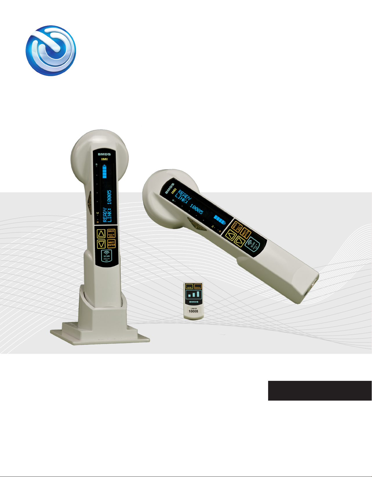
BMDS congratulates you on your purchase of the DAS-8006 Wireless Reader System. The DAS-8006
is our newest generation of wireless reader technology used with our READ-ONLY Implantable Micro-
Transponders the IMI-500 and IMI-1000.
The rmware described in this manual is copyrighted, with all rights reserved by Bio Medic Data Systems.
Under the United States copyright laws, the rmware described in the manual may not be copied,
photocopied, or otherwise reproduced, in whole or in part, without the prior written consent of Bio Medic
Data Systems. Any permitted copies must include the same proprietary and copyright notices as were
afxed to the original. Under these laws, copying includes translating to another language or format.
BMDS warrants our reader product to be free of defects in material and workmanship, under regular use
and service for 90 days from the date of delivery to the original purchaser. This is the sole warranty and
under no circumstances do we assume responsibility for consequential or incidental damages resulting
from the sale, use, handling, or installation of equipment.
2
All attempts have been made to provide you with a manual as comprehensive and factual as possible. However, we reserve
the right to make changes at any time and without notice in prices, colors, material, equipment, specications, models, and
availability. Some of the information in the manual may have been updated since the time of publication; please check with
BMDS for complete details of any updates.
DAS-8006 Parts List
DAS-8006-C DAS-8006-P DAS-8006-IUS
Wireless Com Module Wireless Com Module DC 12V Power Supply
Com Module Bracket DC 12V Power Supply USB Driver Disk
Charging Base USB Driver Disk
DC 12V Power Supply
USB Driver Disk

Stand DAS-Host
Optional with the DAS-8006-P, or
DAS-8006-IUS
Optional companion software.
Host
DAS
Rubber Boot
Optional with the DAS-6006-C
DAS-8006-P, or DAS-8006-IUS
www.BMDS.com 1-800-526-BMDS or 302-628-4100 for Support Questions
DAS-8006 CHECK LIST
DAS-8006 Unit
Charging Base
Wireless Com Module
DC12V Power Supply
Com Module Bracket
BMDS Proprietary USB
Driver
DAS-8006-C, DAS-8006-P or
DAS-8006-IUS
DAS-8006-C only.
Bundled with 8006-C & DAS-
8006-P, optional with DAS-8006-
IUS
Bundled with 8006-C
3
www.BMDS.com 1-800-526-BMDS or 302-628-4100 for Support Questions
CONTENTS
1.
2.
3.
Buttons and Features ................................................................................................. 6
DAS-8006 Models ...................................................................................................... 7
Charging ..................................................................................................................... 8
Battery Replacement .................................................................................................. 9
Keypad Functions ..................................................................................................... 10
Reader Display .................................................................................................... 10-11
Introduction ............................................................................................................... 17
Main Menu.................................................................................................................. 17
Operational Setup.................................................................................................. 17-18
Memory Menu............................................................................................................. 19
Use Loaded Map File ................................................................................................. 19
Time Stamp ................................................................................................................ 20
Data Output ........................................................................................................... 20-21
Load EXC Firmware ................................................................................................... 21
Data Communication Overview ................................................................................ 12
Wireless Communication Module ............................................................................. 13
Reading Micro-Transponders ................................................................................... 14
Mapping Micro-Transponders .............................................................................. 15-16
System Overview
Menus and Functions
Functions
4
www.BMDS.com 1-800-526-BMDS or 302-628-4100 for Support Questions
QUICK START GUIDE
5
To get started, please follow these easy steps.
Please refer to the DAS-8006 User Manual for additional conguration instructions. Additional information
can also be found at WWW.BMDS.COM
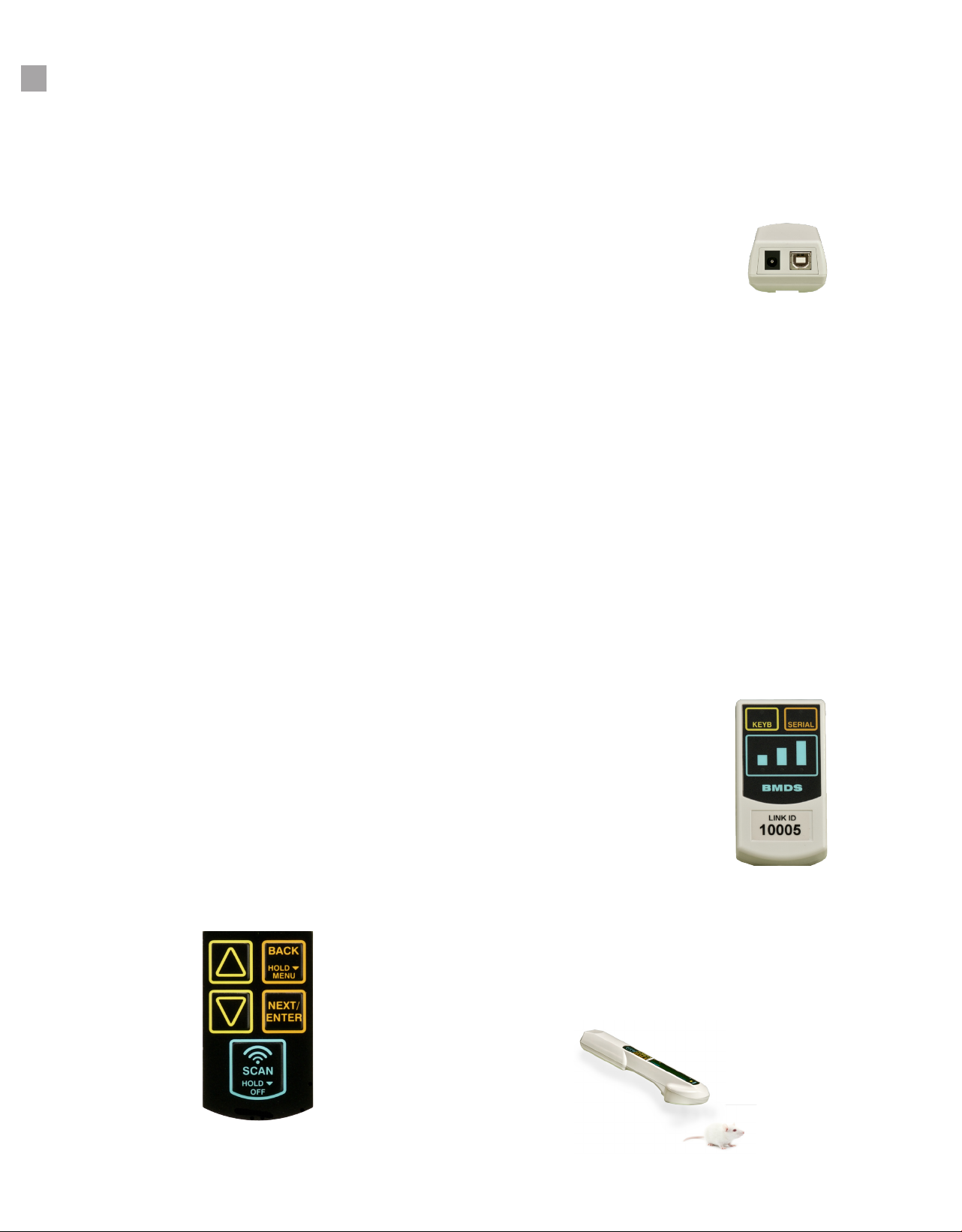
Reader Keypad
There are 5 buttons or keys on the reader unit
SCAN
Press and quick release of this button will turn
the unit on. Press the button again will start the
scan mode. When in scan mode, the blue
LED lights along the side of the reader display
will scroll with the top light labeled S for scan
always being on. Holding down the button for
longer will turn unit off.
BACK
Hold to enter system menu. Also, used to return
to the previous menu/screen.
NEXT/ENTER
Like the Back button, Next/Enter is used to
progress through the menu tree and to conrm
changes to menu items.
DOWN ARROW/ UP ARROW
Used to change menu items from NO to YES or
ON to OFF or other various possible settings.
Refer to system manual for menu settings and
conguration options of the reader.
Connecting to a computer
DAS-8006-IUS
Install DAS-Host software, and the required drivers
(Win XP-7) or plug and play with Win 10 via USB Serial
interface, to connect incoming reader data.
DAS-8006-C and DAS-8006-P
The C and P versions are supplied with a wireless com-
munications module. Conrm that the Link ID of the
module matches the Link ID displayed on the reader.
Communication with the computer can be connected
Keyboard USB requiring no software driver or Serial
USB requiring software driver. For simple data trans-
fer, connect via Keyboard USB, open application and
transmit data. Data scanned or downloaded will auto-
matically populate data elds.
Scanning transponders
To scan for a transponder, press the Scan button. The
blue LED should ash on the display. Hold the scanner
over and parallel with the transponder. Read distance
is approximately 3” from scanner.
Down Arrow
Up Arrow
Back Button
Next/Enter Button
www.BMDS.com 1-800-526-BMDS or 302-628-4100 for Support Questions
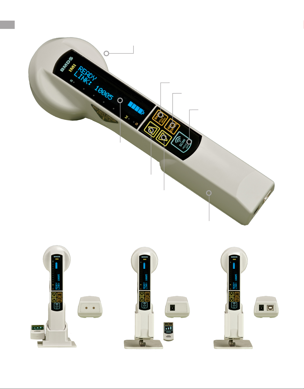
DAS-8006-C, DAS-8006-P, DAS-8006-IUS
6
OLED Display
Reader Head
2 Rechargeable
Batteries
Power/Scan Button
DAS-8006-C DAS-8006-P DAS-8006-IUS

www.BMDS.com 1-800-526-BMDS or 302-628-4100 for Support Questions
7
SYSTEM OVERVIEW
The DAS-8006 is comprised of three different models. DAS-8006-C, DAS-8006-P, and the DAS-8006-IUS.
Identify your unit by inspecting the label on the underside of the reader. You will also nd the serial number
there.
The reader is used in conjunction with the IMI Micro-Transponders; IMI-500, and IMI-1000. The reader will
energize the transponder which will, in turn, send data back to the reader. In addition to the transponder
identication code, the reader can provide an option of date and time stamping at time of the scan. For
optimal scanning, the transponder should be separated from other transponders within the scanning area.
The transponder should be parallel with the unit but slightly in front and below the scan head. When the
reader is powered and the SCAN key pressed, the unit will search for a transponder in the area (within 3”).
Once scanned, the unit will display the transponder code until SCAN is pressed again or for the amount of
time specied by the AUTOSCAN feature.
The scanned data can be stored by the reader internally for further upload or transmitted via either a
wireless communication module or wired USB data cable depending on reader model purchased.
The wireless communication module provides a link from the reader to a computer or tablet by either a
secure Serial USB port or a simple HID Keyboard USB port. The HID Keyboard USB port does not require
a software driver and therefore can be connected to any device capable of connecting via USB cable.
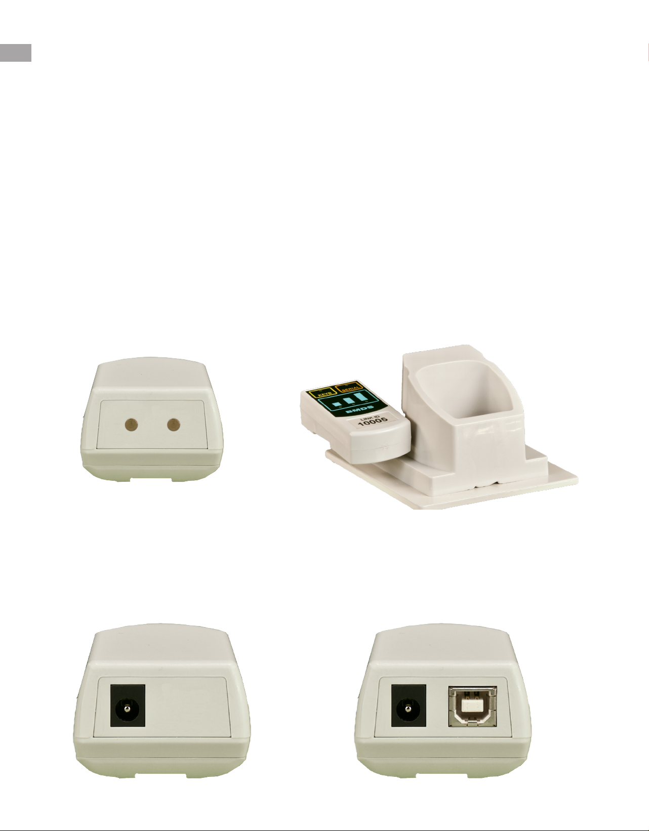
DAS-8006-C (Charging Base Reader)
The DAS-8006-C reader system includes a sealed reader with contact base charging. The contact base of the reader allows for
ease of cleaning. Charging is conducted with the included charging base unit. The unit also includes a wireless communication
module for fast wireless data transfer.
DAS-8006-P (Power Line Charging Reader)
The DAS-8006-P reader system includes a reader with DC plug charging. The plug charging allows for fast connection and use
while being charged. This reader is similar to the DAS-8006-C and includes a wireless communication module for fast wireless
data transfer. An optional stand is available that will help protect the unit from damage by securing the reader while in use for
stationary scanning or can secure the reader when not in use while charging.
DAS-8006-IUS (Integrated USB Serial Reader)
The DAS-8006-IUS reader system includes a reader with DC plug charging. The plug charging allows for fast connection and
use while being charged. This reader does not have a wireless communication module and therefore is the most cost-effective
reader available for wireless transponder identication. Data scanned can be transmitted in real time or downloaded from data
storage using the included Serial USB port. Serial USB does require software driver installation and DAS-Host software. The
DAS-8006-IUS can also be upgradeable to fully wireless communication similar to the DAS-8006-C and DAS-8006-P with an
optional wireless communication module. An optional stand is available that will help protect the unit from damage by securing
the reader while in use for stationary scanning or can secure the reader when not in use while charging.
www.BMDS.com 1-800-526-BMDS or 302-628-4100 for Support Questions
DAS-8006 CHARGING
8
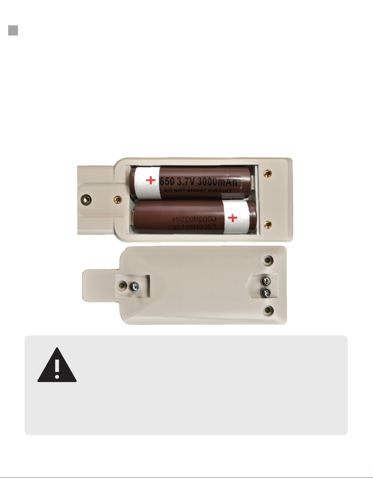
Power for the unit is provided by two rechargeable lithium-ion 3.7v 3000 mAh user replaceable batteries.
Charging of the reader is either done by a contact charging base stand or a direct DC plug depending on
the reader model ordered. The supplied batteries have a lifespan of approximately 1200 full or partially
drained charging cycles. Although there are no memory effects to frequent charging, to maximize battery
life, it is best to charge only when the battery is low. The battery provided allows for hundreds of reads
between charging cycle and therefore should not be a concern.
To charge the DAS-8006-C using the charging base, plug the 12-volt power supply provided to the back
of the base. To recharge the reader supplied with the charging base, simply place the reader back in the
base. The unit will automatically start charging, and the internal microprocessor in the reader will end
charging cycle when completed. The charging base should be located in a dry area and located away
from animal dander and debris. To maximize the life of base contacts, care should also be taken to avoid
any solvents caustic to metal.
To charge the DAS-8006-P and DAS-8006-IUS using the 12-volt power supply provided, simply plug the
reader to the power supply using the plug at the bottom of the reader. The unit will automatically start
charging, and the internal microprocessor in the reader will end charging cycle when completed. Avoid
getting the plug outlet wet to prevent short and/or electrical shock.
www.BMDS.com 1-800-526-BMDS or 302-628-4100 for Support Questions
DAS-8006 BATTERY REPLACEMENT
9
WARNING
The DAS-8006 batteries are rechargeable Lithium-ion cells and are very
powerful. Care should be used to dispose of the used batteries at the proper
recycling center. A re or explosion could result if damaged or if improperly
disposed of. Do not replace batteries with a higher capacity mAh (milliampere-
hour) battery of the same type. Warranty will be voided if incorrect batteries
are used for replacement.
The DAS-8006 uses a microprocessor control charging system that monitors the battery during recharge.
If at some point it becomes necessary to replace the batteries, the user can order a replacement set
directly from BMDS.
To replace the batteries on a DAS-8006, unscrew the battery panel on the back of the reader. There are
three small screws securing the panel. Once the panel is removed, replace the batteries with a new set.
Note the proper placement of the positive and negative for each battery. Secure the panel with the three
screws once batteries have been replaced.

www.BMDS.com 1-800-526-BMDS or 302-628-4100 for Support Questions
DAS-8006 KEYPAD AND DISPLAY
10
DAS-8006 Keypad
SCAN
A press and quick release of this button will turn the unit on. Please
note you must release the button for the unit to turn on. If the button is
pressed again the unit will go into the scan mode. When in scan mode,
the blue LED lights along the side of the reader display will scroll with the
top light labeled S for scan always being on.
To power down the DAS-8006, hold the scan button down for more than
one second (long press) it will turn the unit off.
BACK
This button is used to go back in any menu tree selection. It is also used
for entering and exiting the unit’s menu. This is done by holding (long
press) the button.
NEXT/ENTER
This button is used to progress through the menu tree and to conrm
changes to menu items.
DOWN ARROW
This button is used to change menu items from NO to YES or ON to OFF
or various possible settings. It is also used to sequence a numerical
number and will auto sequence if held down. Arrows symbols will appear
on the screen when the arrows are active.
UP ARROW
Same as above but moving in the opposite direction. Note since the
unit display is viewed sideways and will ip depending on position, the
arrows are actual LEFT and RIGHT or RIGHT and LEFT in actual use.
Regardless of the display orientation they will stay consistent in function.

www.BMDS.com 1-800-526-BMDS or 302-628-4100 for Support Questions
DAS-8006 KEYPAD AND DISPLAY
11
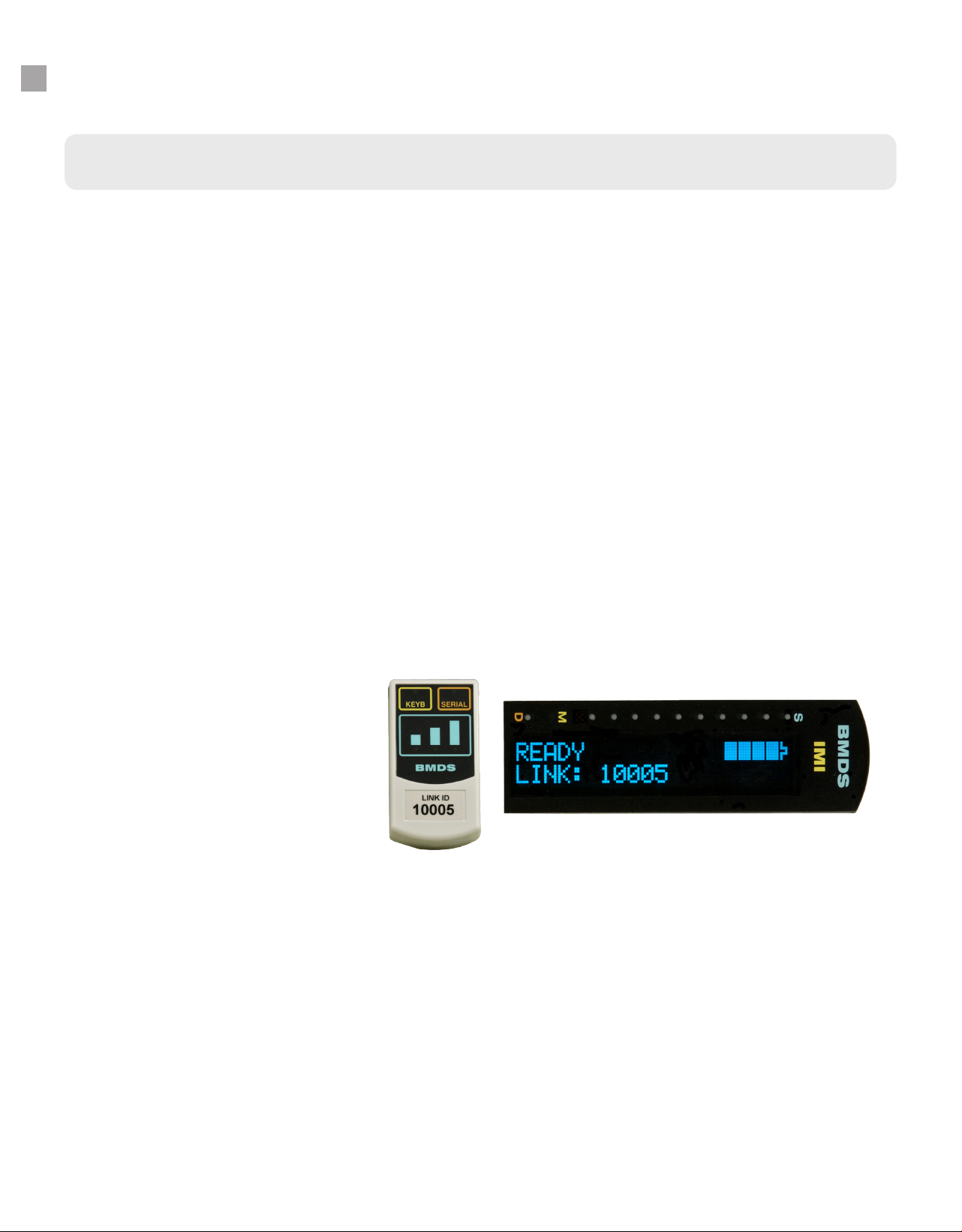
DAS-8006 Display
The reader display is a 20 character by 2 line display. When the unit is turned on (by briey pressing the
scan button), the “READY” screen will appear. This will be the home screen of the unit. The word “READY”
appears in the top left corner. On the right corner is a battery symbol that indicates battery charge level. If
the battery is not fully charged and the unit is in its charging cradle or power plug, the word “CHARGING”
will regularly ash in place of the battery meter. The CHARGING will stop when the unit is fully charged.
Also whenever the unit is connected to power, the 12v will appear directly below the battery symbol. On
the bottom line at left, the word “LINK” and a ve-digit number will be displayed if a wireless module is
activated with the reader. On the DAS-8006-IUS, a wireless module will need to be purchased separately
if the option is enabled (via menu selection).
At the top of the display, there are three indicator LED in addition to a row of blinking LED lights.
• The S when lit indicates Scan mode is active.
• The M when lit indicates that mapping functions are active.
• The D when lit indicates that duplicate lters is activated
• In addition, when the scan button is pressed in the ready screen, the screen will go blank
and a row of 5 blue LED will begin to sequence indicating the unit is in active scanning
mode. In this mode if a transponder is brought within distance to the unit, the reader will
beep, the LED sequencing will stop and the display will activate and display the captured
ID information.

www.BMDS.com 1-800-526-BMDS or 302-628-4100 for Support Questions
DAS-8006 COMMUNICATIONS
12
Connect the supplied Wireless Communications Module via USB to a PC workstation. Once connected
launch your companion application, such DAS-Host, or another active program window.
The module unit has a “Link ID” number on its front that can be set in the wireless reader menu system.
The Link will be displayed on the reader screen to conrm the match ID. Wireless data is transferred
from your DAS-8006 reader via ZigBee, which is a wireless standard that does not interfere with internal
network infrastructure, or other Bluetooth connections. Data may also be stored using onboard memory,
and transfer via USB to a PC workstation when connected. Please be sure to install the supplied USB
drivers before attempting such a connection.
DAS-8006-C & DAS-8006-P
DAS-8006-IUS
As a standard conguration, the DAS-8006-IUS is supplied with only a Serial USB connection for data
transfer to a connected computer. Scanned data will be stored using on-board memory, until transferred
to a computer workstation.
Data Transfer Communication
Communication requires installing a serial USB driver. The connected computer will assign a unique
COM port assignment for use with the data collection software. Drivers are provided for use with Microsoft
Windows XP and 7. Microsoft Windows 10 has native driver support and needs no secondary driver
installation. If needed, contact BMDS for driver support.
Although not necessary, BMDS DAS-Host software is suggested to allow for easy communication with
the computer and associated data collection software. DAS-Host will allow incoming data from the reader
to be transmitted as keyboard entries. Certain commercial software packages will have serial COM port
interfaces but most generic software such as Microsoft Word and Excel does not.
www.BMDS.com 1-800-526-BMDS or 302-628-4100 for Support Questions
DAS-8006 COMMUNICATIONS
13
Wireless Communication Module
Connections
The data connection to the wireless communications module features auto selection between USB Serial
and USB Keyboard ports. Simply connect to the preferred port and note that the front LED automatically
conrms connection. It is best not to have more than one connection being used at a time in order to avoid
data collision.
Serial USB
Serial data output in a USB format is the preferred communication standard for secured data
transfer. Communication requires installing a serial USB driver. The connected computer will
assign a unique COM port assignment for use with the data collection software. Drivers are
provided for use with Microsoft Windows XP and 7. Microsoft Windows 10 has native driver
support and needs no secondary driver installation. If needed, contact BMDS for driver support.
Keyboard USB
Keyboard USB is the suggested connection for standard data transmission. Keyboard USB
or HID USB requires no driver installation and can be used with any Microsoft Windows OS,
Apple MAC OS or even Android and Linux OS. Data transmission from this connection will
appear as standard resulting keystrokes on any active computer program window. Keyboard
USB is therefore the simplest method to communicate when connected to a computer, it should
recognize the connection as a “human interface device” and automatically congure the
connection.
Module Display
This area of the wireless communication module will display connection with the reader during data
transmission. The closer the reader is to the module, the stronger the wireless signal will display. Best
signal strength will result when all three LEDs go temporary ON during transmission. Weakest signal will
result with one LED (left side) light up. No LED indication during a read indicates that the reader is out of
range. Experimentation is recommended to determine maximum range in specic facilities. Transmission
distance can range from 20 feet and more depending on the nature of the walls and ceilings in the facility.
Make sure proper drivers are installed and proper COM settings selected in the active program for SERIAL
connection. If KEYB is connected, no drivers are required.

www.BMDS.com 1-800-526-BMDS or 302-628-4100 for Support Questions
DAS-8006 READING MICRO-TRANSPONDERS
14
For optimal performance, the Micro-Transponder should be separated from other Micro-Transponders
within the scan area. The Micro-Transponder should be in line/parallel below the unit and slightly ahead of
the scan head. When the unit is activated via the SCAN key, the unit will continue to seek a transponder
until a transponder is read or the SCAN key is pressed again to cancel the scanning. The unit has various
features for displaying the collected transponder data, storing it, and sending out data ports.
Do not read the Micro-Transponder from the side or at right angles. Once again the general rule is to
have the length of the probe in line with the length of the transponder, about 1 to 2 inches away. A slight
movement away or towards the transponder will sometimes help.
NOTICE
Performance could be compromised if you attempt scanning the Micro-Transponder
at right angles to the reader. Also closer is not always better unless scanning a
transponder inside the needle assembly. The above information can also be applied
once the transponder is implanted. Note how the probe is above and slightly behind
the transponder. To do this successfully, it is important to be consistent as to implant
orientation. This makes it easier to imagine the location and orientation of the device
when out of view.

www.BMDS.com 1-800-526-BMDS or 302-628-4100 for Support Questions
DAS-8006 MAPPING IMI-500 & IMI-1000
15
Mapping is the process of associating a read-only transponder ID code (i.e. 4A63D23037) with a user
assigned unique code stored in memory. The reader has internal memory which can support a database
le known as a map le. A map le is a collection of records in which each record contains a transponder
ID and a map code that is associated with the transponder ID.
Example Map File:
4C07507E4F/Animal 10001
6D5E54080B/Animal 10002
6D6F45053D/Animal 10003
4C0730056C/Animal 10004
6D5471787D/Animal 10005
Mapping is activated on the reader as an option in the Menu. The reader will read a transponder ID, then
instantly search for the transponder ID stored in the map assignment le. If a match is found, the reader
can display the associated map code in place of the read-only transponder ID code or both the read-only
transponder ID code and assigned mapped transponder ID.
Mapping of transponder ID is done using the DAS-Host Software connected to your DAS-8006 reader
connected to the computer via the Serial USB port. Currently, there are two versions of DAS-Host software
that can be used to create a map le with the DAS-8006 reader. The legacy DAS-Host and the new DAS-
Host 8000 that supports only newer series DAS-8000 readers.
Please refer to the specic DAS-Host User Manuals for full instructions of the simplied steps documented
in procedure below.
Using Legacy DAS-Host to create a Map File
In brief, locate Map on the DAS-Host tool bar menu at the top of the main screen. Click Map and Open
in order to create, and/or append any existing map les. When creating a map le, the default extension
should always be left as .MAP.
IMPORTANT: Prior to mapping, it is important to deactivate timestamping and mapping if currently active.
Failure to deactivate one or all these elds will assign a mapped ID code to each eld.
Once a le has been created, use DAS-Host to send the le to the reader using the Toolbox menu selection
and selecting the Handheld DAS-7006/8006 from the menu drop down box. Click Send Map File from the
section sub-menu. By selecting APPEND in the DAS-Host window prior to sending the le, the le transfer
will append to the original le already in your reader if present. If APPEND is NOT SELECTED, then DAS-
Host will overwrite your original le in your DAS-8006 reader.
Using DAS-Host 8000 to create a Map le
Mapping of transponder ID has been greatly simplied with the new DAS-Host 8000 software. Creating
and sending the Map le is now located in a unied Map Options section on the software screen.
For detailed steps, refer to the DAS-Host 8000 manual.
IMPORTANT: Prior to mapping, it is important to deactivate timestamping and mapping if currently active.
Failure to deactivate one or all these elds will assign a mapped ID code to each eld.

www.BMDS.com 1-800-526-BMDS or 302-628-4100 for Support Questions
DAS-8006 MAPPING IMI-500 & IMI-1000
16
In brief, click CREATE MAP to start the process. When creating a map le, the default extension should
always be left as .MAP (this is a simple text le that can be read with any ASCII reader such as Microsoft
Notepad. The .MAP extension is needed to be recognized by the BMDS reader systems).
Once initiated, a TRANSPONDER MAPPING window will open to begin the process of linking a user
assigned ID to the IMI read-only code. Enter your desired ID code (for example ANIMAL 1004) in the box
under NEXT MAP CODE. If the last character is a number, the program will assign the next sequential
number for each new transponder mapped. Auto Sequence will be checked by default. If consecutive
numbering is not desired, manually uncheck the Auto Sequence box to update code with new information
prior to scanning. Press READ TRANSPONDER in the window and scan your rst transponder. Once
completed, select SAVE FILE AND EXIT to save a MAP le. If a current existing MAP le is entered, the
le will be updated with the new entries.
To use ID mapping, the le will need to be stored in the reader memory. Click UPLOAD MAP to select a
map le to transmit to the reader. Once uploaded, the reader will automatically activate MAP which can be
turned off from DASHost 8000 or within the reader’s menu selection. DASHost 8000 will report the total
number of Map records currently on the upload le once transferred.
Activating a Map le on the DAS-8006 reader
After sending a map le using either DAS-Host software, you may select the On or OFF option in the
reader system menu, USE LOADED MAP FILE (See DAS-8006 MENUS for more information on how to
change the selection). The available selections are:
• NO: Turn off mapping.
• YES: Map the scanned transponder ID to a map code in the stored map le, and only
transmit the mapped code.
If you require displaying BOTH the transponder code and mapped ID, please refer to the specic DAS-
Host software manual to activate that setting.
Briey, BOTH can be activated in the Toolbox System Setup submenu for the Handheld DAS-7006/8006
reader. BOTH is activated in DAS-Host 8000 under the Map Options menu by checking the Xmit Raw and
Mapped box.

www.BMDS.com 1-800-526-BMDS or 302-628-4100 for Support Questions
DAS-8006 MENUS
17
For function and setup, there is a Main Menu for the more commonly used features and then Sub Menus
for settings and lesser used items. To get into the reader menu, rst turn the unit on via the SCAN button. At
the READY screen, hold the BACK button then release. There are six main menu items, AUTO REPEAT
SCAN, OPERATION SETUP, ENTER MEMORY MENU, USE LOADED MAP FILE, TIMESTAMP DATA
and DATA OUTPUT SETUP. Some of the main menu selections have sub menu selections.
While in the menus, pressing the NEXT button moves you through the menu items unless you select YES
to any option that leads into a Sub menu. You can use the BACK button to exit up or back out. Use the
NEXT button to progress through the menu. Holding the BACK button will exit you to the READY screen.
In all cases the arrow keys are used to change settings of each menu item.
The Main Menu items described below are listed in BLUE and the Sub Menu items will be listed in
ORANGE.
MENU
AUTO REPEAT SCAN < OFF/ON >
Default setting is OFF. Used to set the reader to scan automatically without having to press the
scan button after each scan. During auto-scanning mode, the top two LED lights will blink to indicate
mode is active and counting down the timer between scans.
Be aware that in auto-scan, battery will drain faster since the reader remains searching for a
transponder. The unit can also become detuned if placed in scan mode while on a metal surface.
Detuning will reduce operational effectiveness of the scanner and shorten lifespan of the reader.
OPERATIONAL SETUP < NO/YES >
Operational Setup provides access to sub menus dealing with reader operation that are changed
infrequently. Select YES to enter the Sub Menus.
CHANGE WIRELESS ID < NO/YES/DISABLE WIRELESS >
Option to change the link ID to match a different wireless communications module or turn the
feature off all together. The DAS-8006-IUS is shipped with no communication module and
wireless option disabled.
AUDIO BEEP < OFF/ON >
Default setting is ON. Option allows for turning on or off the beep sound that occurs in
various functions including successful transponder read.
VIBRATE UPON READ < OFF/ON >
Default setting is OFF. Option allows for a soft vibrate to indicate a successful transponder
read which is useful in noisy environments such as kennels and primate enclosures.

www.BMDS.com 1-800-526-BMDS or 302-628-4100 for Support Questions
DAS-8006 MENUS
18
SCAN DELAY FOR AUTO < 1-900 SECOND >
Default setting is 3 seconds. Here you can set how fast the unit will begin active scanning
after a successful read in the auto mode. The scan delay will be indicated by the top two
LED blinking after each successful read while the timer is counting down. Be aware that
900 seconds equals 15 minutes and therefore the unit should be plugged in to avoid power
save turning reader off.
AUTO MODE DUP FILTER < OFF/ON >
Default setting is OFF. Option allows for protection against accidental duplicate reading of
the same transponder in a row. The reader will light up the LED at the far right next to the
D to indicate DUP FILTER is active.
Once a transponder with a certain ID has been scanned, the reader will only read a
transponder in the next subsequent scan with a different transponder code. DUPLICATION
FILTER VIOLATION will be displayed if the same transponder is scanned.
POWER SAVE/TIMED OFF < 1-15 MINUTE >
Default setting is 15 MINUTES. The unit will turn off if a transponder is not read within a
certain length of time. This allows the user to set that time between 1 and 15 minutes.
PASSWORD FOR MENU < NO/YES >
Default setting is NO. This feature will require the user to enter a 4-digit password in order
to enter the main menu. If YES is selected, the unit will go to a screen that allows the
user to select a password of their choice. Password will prevent access to all menu item so
care should be taken to note any password settings and record password. Once set, the
unit will display the menu below in place of the above:
PASSWORD IS SET < OK/CHANGE OR CANCEL >
FIRMWARE VERSION < 2.1.X >
This screen displays the version of the rmware loaded into the unit. The version number
will be needed for any customer support issues.
HOURS USED METER XX HOURS
This screen displays the number of hours the unit has been in use.

www.BMDS.com 1-800-526-BMDS or 302-628-4100 for Support Questions
DAS-8006 MENUS
19
ENTER MEMORY MENU < NO/YES >
Memory Menu provides access to sub menus allowing for data saved functions of scanned Micro-
Transponders to the unit memory and subsequent download at a later time.
STORE DATA RECORDS < NO/YES >
Default setting is NO. Select YES to store scanned activity (including date/time stamping) to
the reader internal memory. The unit allows 10,000 records with oldest record being erased
for new additions. Please note that downloading of 10,000 records will require a long transfer
period so it is best to download data after each or a few collection sessions.
NUMBER OF RECORDS 10000 RECORDS
This screen will display how many data records are stored. A warning message is displayed
if you exceed memory capacity.
DOWNLOAD RECORDS < NO/YES-AT SERIAL SPEED/YES-AT KEYBRD SPEED >
Default setting is NO. Option allows for downloading of stored records to a connected
computer through either Serial USB (DAS-8006-IUS) or wireless (DAS-8006-C and DAS-
8006-P). If you are connected by serial USB, use the faster YES-AT SERIAL SPEED. If you
are connected to the keyboard port, use the slower YES-AT KEYBRD SPEED. As records
are sent, the screen will show records sent count. Note that Serial USB will require driver
installation and Windows OS. Keyboard USB can communicate with any USB capable
device and requires no software driver installation.
NOTE: Records downloaded will remain on the reader in stored memory until
deleted by Clear Records. See steps for clearing records below.
CLEAR STORED RECORDS < NO/YES >
Default setting is NO. Selecting YES and pressing the NEXT/ENTER button will clear all
scanned and stored transponder data from the unit memory. There is no recovery for deleted
collected data.
USE LOADED MAP FILE < NO/YES >
Default setting is NO. The reader has an internal database storage for storage of a MAP le.
The MAP le allows for the substitution of a cross referenced ID or “MAPPED” ID for the original
scanned transponder code. Crossed referenced IDs are based on a list of IDs that has been loaded
as a “MAP FILE” into the unit.
Currently BMDS DAS-Host software program is required to create and load a map le. A warning
message is provided if this option is selected without an active map le loaded.

www.BMDS.com 1-800-526-BMDS or 302-628-4100 for Support Questions
DAS-8006 MENUS
20
TIIMESTAMP DATA < NO/DATE & TIME/DATE ONLY/TIME ONLY SET DATE AND TIME >
Default setting is NO. The reader has the ability to store a date/time stamp with each scanned
record. The information will not be displayed on the reader but will be sent in the output data
stream. The time stamping will be added before the actual transponder code. Options are available
to either select time and date, just the date, or just the time.
Additionally, the date and time can be set or updated. Selecting this will lead you through a series of
screens in which the two arrow keypads are used to select YEAR, MONTH, DAY, HOUR, MINUTES.
DATA OUTPUT SETUP < NO/YES >
Data Output Setup provides access to sub menus allowing for setting parameters for transmission
of data sent from the reader to a connected computer.
FIELD DELIMITER < CRLF/TAB/COMMA/CR/NONE >
Default setting is TAB. Select a different delimiter setting using the arrow keys to select a
desired delimiter to separate each data eld (Date, Time, Transponder code). For example,
if time stamp is enabled, this is the delimiter being sent after the date/time but before the ID
to the active open software connected to the reader.
The available delimiters are:
• CRLF – This will transmit two characters for the delimiter: a Carriage Return
character (ASCII 13) and a Line Feed character (ASCII 10).
• TAB – This will transmit a Tab character (ASCII 9).
• COMMA – This will transmit a comma character (ASCII 44).
• CR – This will transmit a Carriage Return character (ASCII 13).
• NONE – No delimiter transmitted with sent data.
This manual suits for next models
3
Table of contents
Popular Medical Equipment manuals by other brands


Playcore
Playcore SPECTRUM Aquatics Freedom Lift 57961 manual

Stryker
Stryker Atlas 660Z Maintenance manual

Mackworth
Mackworth HOLLY User instructions

Prestige
Prestige 24i LQ MG manual

Mortara Instrument
Mortara Instrument ELI 100 Service manual

Orliman
Orliman MANUTEC FP-75 INSTRUCTIONS FOR USE AND PRESERVATION