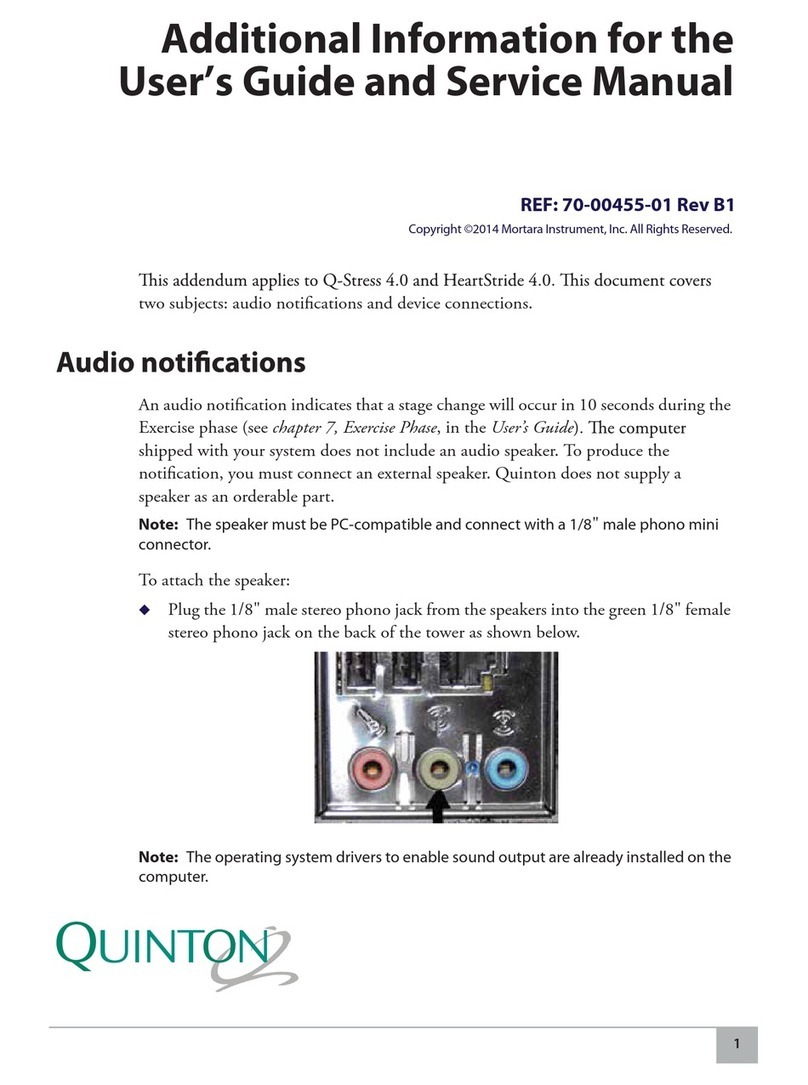
Mortara Instrument ELI 100 User manual

REF 9507-008-50 REV E1
ELI 100 Service Manual
CAUTION: Federal law restricts this device to sale by or on the order of a physician.


®
Copyright© 1996-2006
by Mortara Instrument, Inc.
7865 N. 86th Street
Milwaukee, Wisconsin 53224
This document contains confidential information that belongs to Mortara Instrument, Inc. No part of this document may be
transmitted, reproduced, used, or disclosed outside of the receiving organization without the express written consent of Mortara
Instrument, Inc. Mortara is a registered trademark of Mortara Instrument, Inc. ELI 100 is a trademark of Mortara Instrument,
Inc.


i
Table of Contents
1 General
Service Manual Purpose ......................................................................................................1-1
User Safety Information ........................................................................................................1-1
Periodic Safety Inspections .....................................................................................1-1
Proper Power Cord ..................................................................................................1-1
Proper Fuse .............................................................................................................1-1
Do Not Operate in Explosive Atmospheres .............................................................1-1
Use Only Safe Methods of Interconnection .............................................................1-1
Do Not Mount Product above Patient ......................................................................1-1
Recommended Accessories ....................................................................................1-1
Sterilizing this Product .............................................................................................1-2
Liquid Spills .............................................................................................................1-2
System Information Log ...........................................................................................1-2
Product Information .................................................................................................1-2
Equipment Symbols ..............................................................................................................1-2
Symbol Delineation ..................................................................................................1-2
2 Maintenance and Cleaning
Introduction (Maintenance and Cleaning) .............................................................................2-1
Recommended Cleaning Supplies .......................................................................................2-1
List of Repair Materials .........................................................................................................2-1
Cleaning and Inspection Techniques ...................................................................................2-2
Interior Cleaning ...................................................................................................................2-2
Magnetic Cleaning ................................................................................................................2-2
Printed Circuit Board Cleaning .............................................................................................2-2
Metallic and Plastic Parts Cleaning ......................................................................................2-3
Exterior Cleaning ..................................................................................................................2-3
Printhead Cleaning ...............................................................................................................2-3
Inspection of Writer Assembly Harness ...............................................................................2-3
Printhead Adjustment ...........................................................................................................2-3
Exterior Inspection ................................................................................................................2-4
Interior Visual Inspection ......................................................................................................2-4
Preventive Maintenance Schedule .......................................................................................2-4
Cover Assembly Removal / Installation ................................................................................2-5
Writer Removal / Installation .................................................................................................2-5
Printhead Removal / Installation ...........................................................................................2-5
Paper Drive Motor Removal / Installation .............................................................................2-6
Printed Circuit Board Assembly Removal / Installation ........................................................2-6
Keyboard Removal / Installation ...........................................................................................2-6
LCD Removal / Installation ...................................................................................................2-7
Batteries Removal / Installation ............................................................................................2-7

ii
3 Technical Description
Introduction (Technical) ........................................................................................................3-1
Processor Module (MPM) .....................................................................................................3-1
Modem Module (MMM) ........................................................................................................3-1
Main System Board ..............................................................................................................3-2
RS-232 Level Serial Port / High Speed Serial Port .................................................3-2
Writer Interface ........................................................................................................3-2
Writer Motor Control.................................................................................................3-2
Printhead Signal and Power Interface .....................................................................3-3
Keyboard Interface ..................................................................................................3-3
LCD Interface ..........................................................................................................3-3
Patient Input .............................................................................................................3-4
Speaker Interface ....................................................................................................3-4
Power Management Circuit .....................................................................................3-4
Power Supply ........................................................................................................................3-5
AC Input Power .......................................................................................................3-5
Battery Connections ................................................................................................3-5
Battery Charger and Printhead Supply ....................................................................3-5
5V Logic Supply .......................................................................................................3-5
5V Back-up Supply ..................................................................................................3-6
12V Programming Supply ........................................................................................3-6
Block Diagram ......................................................................................................................3-7
Keyboard Matrix ....................................................................................................................3-8
Battery Charging ...................................................................................................................3-8
Interconnection Diagram ......................................................................................................3-9
Interconnection List ..............................................................................................................3-10
RS-232 / High-Speed Serial Data Port ....................................................................3-10
AC Power Input .......................................................................................................3-10
Battery Input ............................................................................................................3-10
Writer Motor .............................................................................................................3-10
Writer Control / Power .............................................................................................3-11
Patient Input .............................................................................................................3-11
LCD Display Interface ..............................................................................................3-12
Spare Slot ................................................................................................................3-12
MPM Board Slot ......................................................................................................3-12
Keyboard Interface ..................................................................................................3-12
Engineering Debugger Interface .............................................................................3-13
4 Final Assembly
Parts List #1 - Final Assembly ................................................................................................4-1
Modem Card Optional Assembly Procedure ..........................................................................4-3
Modem Options ......................................................................................................................4-4
Final Assembly Notes ............................................................................................................4-5

iii
5 Base Assembly
Parts List #2 - Base Assembly ..............................................................................................5-1
Base Assembly Notes ..........................................................................................................5-3
6 4” Writer Assembly
Parts List #3 - Writer .............................................................................................................6-1
Writer Assembly Notes..........................................................................................................6-3
7 Printed Circuit Boards
Introduction to Printed Circuit boards....................................................................................7-1
Motherboard Ref: 26025-002-50 .............................................................................7-2
Motherboard Board Assembly Notes ......................................................................7-5
Motherboard Schematic Sheet 1 .............................................................................7-6
Motherboard Schematic Sheet 2 .............................................................................7-7
Motherboard Schematic Sheet 3 .............................................................................7-8
Motherboard Schematic Sheet 4 .............................................................................7-9
Motherboard Schematic Sheet 5 .............................................................................7-10
Processing Module (MPM) Board Ref: 26025-005-50.............................................7-11
Processing Module Assembly Notes Ref: 26025-005-50.........................................7-12
Processing Module (MPM) Board Ref: 26025-005-51.............................................7-14
Processing Module Assembly Notes Ref: 26025-005-51.........................................7-15
8 Testing and Troubleshooting
Equipment Required .............................................................................................................8-1
Introduction to Testing and Troubleshooting ........................................................................8-1
Fault Isolation Table .............................................................................................................8-1
Fault Isolation Table continued .............................................................................................8-2
Diagnosis ..............................................................................................................................8-2
1.0 AC On - Blank LCD, No Pixels Illuminated ........................................................8-2
2.0 AC On - Bar Across Top of LCD or Faint Illumination of Pixels ........................8-3
3.0 DC On - "Battery Low" Message Appears on Display .......................................8-3
4.0 DC On - No Response When DC 'ON' Key is Pressed .....................................8-3
5.0 Writer Test - Printing too Light or Too Dark or Uneven .....................................8-3
6.0 Writer Test - Gaps in Printing, Missing Dots, or No Printing at All ....................8-4
7.0 Writer Test - No Motor Drive .............................................................................8-4
8.0 Modem Test - No Dial-Tone or Touch-Tone Audio ...........................................8-5
Performance Testing ............................................................................................................8-5
Introduction to Performance Testing .......................................................................8-5
Equipment Required ................................................................................................8-5
Test Equipment Set-Up ...........................................................................................8-6
Initial Set-Up ............................................................................................................8-6
Noise Test ...............................................................................................................8-7
ECG, Keyboard and Cable Test ..............................................................................8-8
Rhythm Test ............................................................................................................8-8
Lead Fail Test ..........................................................................................................8-9
Directory Test ..........................................................................................................8-9
Transmit/Receive Test .............................................................................................8-10

iv
Direct Receive .........................................................................................................8-10
Modem Transmission ..............................................................................................8-11
Modem Receive .......................................................................................................8-11
Writer Self Test ........................................................................................................8-12
Description of Leakage Tests ..................................................................................8-12
Leakage Tests .........................................................................................................8-12
Earth Leakage Current Measurement .....................................................................8-12
Chassis Leakage Current Measurement .................................................................8-14
Patient Leakage Current Measurement ..................................................................8-15
Line Voltage Applied to Patient Connection Leakage Current Measurement .........8-16
Ground Integrity Test ...............................................................................................8-16
Appendix A Testing and Troubleshooting
Traces ...................................................................................................................................A-1
Appendix B Modem Module(s) (MMM)
Introduction to Modem Module(s) (MMM) ............................................................................B-1
Modem Module (MMM) 2 MRAM PCB Ref: 26025-003-50...................................................B-2
Modem Module (MMM) 2 MRAM PCB Ref: 26025-003-50 Assembly Notes .......................B-3
Modem Module (MMM) 16 MRAM PCB Ref: 26025-003-51.................................................B-6
Modem Module (MMM) 16 MRAM PCB Ref: 26025-003-51 Modification Notes..................B-7
Appendix C Mortara Receiver Module(s) (MRM)
Introduction to Mortara Receiver Module(s) (MRM) .............................................................C-1
Mortara Receiver Module (MRM-915) PCB Ref: 26125-001-50...........................................C-1
Mortara Receiver Module (MRM-915) PCB Ref: 26125-001-50 Assembly Notes................C-2
Mortara Receiver Module (MRM-2500) PCB Ref: 26125-002-50.........................................C-4
Mortara Receiver Module (MRM-2500) PCB Ref: 26125-002-50 Modification Notes ..........C-6
Index.............................................................................................................................................I-1
Figures
Table 1 - Preventative Maintenance Schedule ...........................................................................2-4
Block Diagram - AC Power .........................................................................................................3-7
Keyboard Matrix ..........................................................................................................................3-8
Interconnection Diagram 1 ..........................................................................................................3-9
4-a Completed Final Assembly ...................................................................................................4-2
4-b Assembling Modem Card ......................................................................................................4-3
4-c Modem Installation ................................................................................................................4-4
4-d Label Placement on Writer ...................................................................................................4-5
4-e Serial Number and Part Number Label Placement on Bottom of Unit .................................4-6
4-f Label Placement on Unit ........................................................................................................4-7
4-g Label Chart ...........................................................................................................................4-7
4-h Ground Label Placement on Unit ..........................................................................................4-8
4-i Cover on Base Installation .....................................................................................................4-9
4-j Writer Door Installation ...........................................................................................................4-10
4-k Writer Installation ..................................................................................................................4-11
4-l LCD and Keyboard Installation ..............................................................................................4-12

v
4-m Tape Placement ...................................................................................................................4-13
5-a Complete Base Assembly .....................................................................................................5-2
5-b Installing Tie Downs ..............................................................................................................5-3
5-c Labeling and Assembly of Batteries ......................................................................................5-4
5-d Installing Printed Circuit Board .............................................................................................5-5
6-a Complete Writer Assembly ...................................................................................................6-2
6-b Addition of Date Code Label and Bench testing ...................................................................6-3
6-c Installing Printhead and Copper Braid Cable ........................................................................6-4
6-d Installing E-Rings to Cover ...................................................................................................6-5
6-e Installing Main Pivot Shaft ....................................................................................................6-6
6-f Installation of Spring Bar ........................................................................................................6-7
6-g Installing Slider Plate ...........................................................................................................6-8
6-h Installing Alignment Deflector Shaft ......................................................................................6-9
6-i Installing Floating Cover and Grounding Gaskets .................................................................6-10
6-j Detail of Spring .......................................................................................................................6-11
6-k Installing Latch and Springs ..................................................................................................6-12
6-l Installing Slide Shaft, Bearing and Spring .............................................................................6-13
6-m Lower Chassis Complete .....................................................................................................6-14
6-n Completion of Lower Chassis ...............................................................................................6-15
6-o View of Bottom of Paper Trough ...........................................................................................6-16
6-p Installation of 48 Tooth Gear ................................................................................................6-17
6-q Installation of Platen and Gears ............................................................................................6-18
6-r Installation of Motor and Sound Dampeners..........................................................................6-19
7-a Motherboard ..........................................................................................................................7-2
7-b Motherboard 'X-Y' Coordinates .............................................................................................7-3
7-c Installation Details .................................................................................................................7-4
7-d Modification Detail .................................................................................................................7-4
7-e Sheet 1 of Motherboard Schematics ....................................................................................7-6
7-f Sheet 2 of Motherboard Schematics .....................................................................................7-7
7-g Sheet 3 of Motherboard Schematics ....................................................................................7-8
7-h Sheet 4 of Motherboard Schematics ....................................................................................7-9
7-i Sheet 5 of Motherboard Schematics ......................................................................................7-10
7-j Processing Module (MPM) Printed Circuit Board Ref: 26025-005-50....................................7-11
7-k Processing Module Card (MPM) 'X' & 'Y' Coordinates Ref: 26025-005-50 and -51..............7-13
7-l Processing Module (MPM) Printed Circuit Board Ref: 26025-005-51....................................7-14
7-m Sheet 1 of 3 Schematics for MPM Printed Circuit Board Ref: 26025-005-50 and -51.........7-16
7-n Sheet 2 of 3 Schematics for MPM Printed Circuit Board Ref: 26025-005-50 and -51..........7-17
7-o Sheet 3 of 3 Schematics for MPM Printed Circuit Board Ref: 26025-005-50 and -51..........7-18
Table 2 - Default Parameters ......................................................................................................8-6
Table 3 - Lead Fail Test ..............................................................................................................8-9
8-a Measuring Device Forms ......................................................................................................8-13
8-b Chassis Leakage ..................................................................................................................8-14
8-c Patient Sink Current ..............................................................................................................8-15
8-d Patient Source Current ..........................................................................................................8-16
A-a Trace 1 - Noise / Drift Test ...................................................................................................A-1
A-b Trace 2 - 12-Lead Auto ECG ................................................................................................A-2
A-c Trace 3 - Rhythm Strips ........................................................................................................A-3
A-d Trace 4 - Directory ................................................................................................................A-4
A-e Trace 5 - Writer Self Test .....................................................................................................A-5
B-a Modem Module (MMM) 2 MRAM Printed Circuit Board Assembly Ref: 26025-003-50........B-2
B-b Views and Details for Mounting Crystal.................................................................................B-3
B-c Modem Module (MMM) 2 MRAM Board 'X' & 'Y' Coordinates Ref: 26025-003-50...............B-4
B-d Modem Module (MMM) 2 MRAM Schematic Ref: 26025-003-50.........................................B-5
B-e Modem Module (MMM) 16 MRAM Printed Circuit Board Assembly Ref: 26025-003-51......B-6
B-f Installation of C27 and D100..................................................................................................B-7
B-g Installation of R8 and C101...................................................................................................B-7

vi
B-h Installation of R102................................................................................................................B-8
B-i Installation of R101.................................................................................................................B-8
B-j Installation of CR2 ..................................................................................................................B-9
B-k Modem Module (MMM) 16 MRAM Schematic Ref: 26025-003-51.......................................B-10
C-a Mortara Receiver Module (MRM-915) PCB Assembly Complete Ref: 26125-001-50..........C-1
C-b Shield Can Installation Holes................................................................................................C-2
C-c Installation of Shield Can.......................................................................................................C-2
C-d Installation of Connectors......................................................................................................C-3
C-e Mortara Receiver Module (MRM-2500) PCB Assembly Complete Ref: 26125-002-50........C-4
C-f Installation of Connectors.......................................................................................................C-5
C-g Installation of MDC-2500 Assembled Printed Circuit Board .................................................C-6

___________________________________________________________________________ Section 1
1-1
1 General
Service Manual Purpose
The purpose of this manual is to supply information to service personnel so they can maintain the ELI 100 12-Lead
Electrocardiograph at the assembly and subassembly level. Although the manual includes parts lists, mechanical
assembly parts, and printed circuit board information, it is intended to function primarily as a guide to preventative
and corrective maintenance and electrical repairs considered field repairable.
User Safety Information
Periodic Safety Inspections
Follow the recommended maintenance schedule. Inspect the power cord and transmission cables
periodically for fraying or other damage and replace as needed. Broken or frayed wires may cause
interference or loss of signal. Pay particular attention to points where wires enter connectors.
Proper Power Cord
Use only the power cord specified for the equipment. This product requires a three-wire, (18 gauge, SJT-
grade) power cord, which is supplied with a three-terminal, polarized plug (hospital grade) for connection
to the power source and protective ground. Use only a power outlet with a protective ground outlet. An
interruption of the grounding connection could cause an electrical shock hazard.
Proper Fuse
Use only the fuse specified for the equipment (identical in type, voltage and current rating). Substituting a
different fuse type could cause a fire hazard. Always make sure fuses have been installed before operating
the unit.
Do Not Operate in Explosive Atmospheres
Do not operate the ELI 100 in the presence of flammable gasses or anesthetics; this environment could
cause an explosion. Refer to Operator's Manual Safety Information: Warning(s) and Caution(s).
Use Only Safe Methods of Interconnection
To prevent electrical shock from the product when it is connected to other electrical equipment, proper
grounding is essential. Refer to Operator's Manual Safety Information: Warning(s) Peripheral equipment.
Do Not Mount Product above Patient
Do not mount or place the product where it could fall on a patient or where it could be accidentally knocked
off a shelf or other mounting arrangement.
Recommended Accessories
For the patient's safety and optimum equipment performance, use only the accessories specified by Mortara
Instrument, Inc.

ELI 100_____________________________________________________________________________
1-2
Sterilizing this Product
Do not sterilize this product or any accessories unless specifically directed by the manufacturer. Sterilization and
sterilization environments can seriously damage many components and accessories.
Liquid Spills
Do not set beverages or other liquids on or near the ELI 100, and/or optional equipment.
System Information Log
See Appendix "A" of Operator's Manual
Product Information
See Section 1 of Operator's Manual
Equipment Symbols
Symbol Delineation
Electrostatic sensitive devices

____________________________________________________________________________Section 2
2-1
2 Maintenance and Cleaning
CAUTION:
Remove battery fuse at right rear of unit before attempting any disassembly. Also,
removing the fuse at the right rear of the unit will cause the configuration parameters
to reset to the default setting. In addition, all ECGs stored in memory will be lost.
Introduction
This section provides servicing and maintenance instructions for the ELI 100 interpretive electrocardiograph.
Subsequent parts of this section are disassembly, inspection techniques, cleaning techniques, and installation.
Recommended Cleaning Supplies
•Anti-static mat & wrist band, properly grounded
•Clean, lint-free cloth
•Cleaning solvent (isopropyl alcohol, 99% pure)
•DRY, low pressure, compressed air (30 psi)
•Electronic safe non-residue solvent, such as Flux-off
•Masking tape
•Non-metallic, soft-bristle brush
•Naphtha
•Vacuum cleaner, Static Safe
List of Repair Materials
•Screwdriver Philips #2.
•Screwdriver, flatblade.
•Nutdriver set, standard.
•Multimeter.
•Oscilloscope.
Note: The equipment and solvent mentioned above are standard shop commodities that are available from
commercial sources. If in the performance of normal maintenance or repair, the PCB assembly, AC
connector assembly, AC switch assembly, or writer assembly are removed or replaced, a leakage test
should be performed. See section on testing.

ELI 100_____________________________________________________________________________
2-2
Cleaning and Inspecting Techniques:
This section contains instructions for periodic cleaning and inspection of the instrument as preventative maintenance
measures. It also contains specific cleaning procedures to be conducted after disassembly. Parts having identical
cleaning procedures are grouped under common headings. No special tools are required.
Interior Cleaning:
WARNING
Ventilate work area thoroughly when using solvents. Observe manufacturers warnings on
solvent containers with regard to personnel safety and emergency first aid. Be sure that first
aid equipment is available before using chemicals. Observe shop safety and fire
precautions. Ventilate all work areas where solvents are used. Store solvents and solvent-
soaked rags in approved containers. Refer to manufacturers’ instructions on containers for
recommended fire-fighting procedures, and make sure that fire-fighting equipment is
available.
Magnetic Cleaning:
CAUTION
Do not use solvents to clean transformers or inductors. The chemical action of solvents may
remove the varnish from the wire coils, rendering the components useless. The solvent also
neutralizes the adhesive of the cover tape, resulting in eventual tape separation from the
windings.
Clean transformers and inductors with a dry, non-metallic, soft bristle brush.
Printed Circuit Board Cleaning.
Clean assembled parts with a vacuum cleaner or low pressure compressed air (60 psi). Take care when cleaning
printed circuit boards that wires or component leads are not bent back and forth in such a manner as to weaken them
and cause them to eventually break.
Prior to soldering, clean surfaces with a nonmetallic, soft bristle brush dipped in solvent.
Dry with low pressure compressed air.

____________________________________________________________________________Section 2
2-3
Metallic and Plastic Parts Cleaning
CAUTION
Do not wipe over surfaces of nameplates or labels with abrasive cleaners or materials, as
this will eventually wear away the nameplate information. Do not use solvents to clean
plastic parts.
Brush all surfaces and parts with a nonmetallic, soft bristle brush.
Wipe metal surfaces with soft, nonabrasive cloth dampened with isopropyl.
Dry surfaces with clean cloth.
Wipe surfaces of nameplates and labels with dry cloth.
Exterior Cleaning.
Use a damp cloth to clean external covers and the line cord. Do not use alcohol, solvents, or cleaning solutions.
These cleaning agents may damage the surfaces of the instrument.
Printhead Cleaning
Open the writer cover as explained in the section on final assembly.
Apply isopropyl alcohol to a clean cloth, and wipe the writer printhead until all foreign matter is removed.
After cleaning is completed, inspect the unit using the techniques described previously.
After the inspection is complete, install the cover as explained in the section on final assembly.
Inspection of Writer Assembly Harness
Visually inspect the wire harness for wear, maintenance damage, corrosion, deterioration, and damage resulting
from dropping.
If no defects are found, install the cover and restore the unit to service.
If a defect is found in the cable, replace it with a new cable.
Note: The removal of the writer assembly as explained later in this section, may be necessary to replace the
cable. After a cable is replaced, re-install the cover.
Printhead Adjustment
Refer to section on Testing and Troubleshooting.

ELI 100_____________________________________________________________________________
2-4
Exterior Inspection
Visually inspect the entire instrument for wear, maintenance damage, corrosion, deterioration, and damage resulting
from dropping.
Interior Visual Inspection
Check components, wiring, solder joints and printed circuit conductor patterns.
Check all connectors for loose, bent or corroded contact points
Check wire, harnesses and cables for signs of wear or deterioration.
Inspect sleeve and tubing for proper installation or evidence of damage.
Inspect components and their leads for security of mounting, deterioration or leakage.
Check terminals and connections for proper installation, failed soldering, loss or wear.
Inspect PCB surfaces for charring, cracking or brittle’s.
Note: Some degree of discoloration of the PCB surface may be expected due to continued exposure to the
operating temperatures of some of the components.
Check the identification nameplate and other decals for legibility.
Inspect chassis, covers, and brackets for warping, bending, surface damage or missing captive hardware.
Check all screws and nuts for tightness or signs of stripped or crossed threads.
Check for damage traces on PCBs. Look for lifted conductors and inspect for breaks, scratches, nicks, or pin holes.
Check for any other form of mechanical damage in which may indicate a failure.
If, during the process of normal maintenance or repair, the PCB assembly, AC connector assembly, AC switch
assembly, or writer assembly are removed and replaced, perform the leakage test as describe in the section on
Testing and Troubleshooting.
Preventative Maintenance Schedule:
Maintenance to be Performed Period Notes
Clean and inspect unit. 6 mo. Perform every 3 mo. if unit is in heavy use.
Printhead cleaning 80 hrs Perform every 40 hrs, if unit is being used with
ELI-XR.
Check printhead wire harness. 160 hrs -
Printhead adjustment - Adjust printhead when print head is replaced.
Leakage tests. - -
Table 1

____________________________________________________________________________Section 2
2-5
Cover Assembly Removal / Installation
Open the writer cover and remove the six flathead screws securing it. They are located at the front and on both sides
of the unit, near the bottom.
Lift the cover assembly gently and tilt it towards the right side of the unit as seen from the front. Set the cover
assembly on its right side.
Unplug the paper drive motor cable (J6 of PCB), the power/data cable (J9 of PCB), the two keyboard cables (J4 of
PCB), and the LCD cable (J1 of PCB). Remove the writer mounting screw that holds the ground wire.
Note: Orientation for the J4 keyboard plug is as follows:
P12 is marked with 1 on one half of the flex tape. This half of P12 goes to J4 pin 9 of PCB.
The other half of the flex tape is marked with 9. This half plugs into J4 pin of the PCB.
J4 pin 9 is adjacent to pin 1.
Set the cover assembly aside with the top facing up. Reassemble on reverse order.
Writer Removal / Installation:
Remove the four Philips screws, which attach the cover assembly to the base of the unit. They are located at the
front and at both sides of the unit, near the bottom.
Unplug the printhead cable.
Remove the remaining writer mounting screws on the under side of the cover assembly.
Lift the writer from the tray and pull the paper drive motor cable through the slot at the rear of the tray. It may be
necessary to do some maneuvering with the connector. Reassemble in reverse order and see note under Printhead
Removal below.
Printhead Removal / Installation:
Remove the four printhead-mounting screws. If a tool is available for removing the E-rings, remove them from both
ends of the metal support bar and remove the bar in order to facilitate printhead removal.
Slide the printhead forward and gently press down on the printhead connector until it clears the lid assembly.
Remove the printhead. Reassemble in reverse order.
CAUTION
When installing a new printhead, make sure that the front edge of the printhead lines up
flush with the front of the lid before tightening the mounting screws. After the unit is
reassembled, run the writer self test as described under performance testing in the section
on Testing and Troubleshooting. It may be necessary to loosen the screws and skew the
printhead slightly at the top or bottom in order to get even printing across the entire trace.

ELI 100_____________________________________________________________________________
2-6
Paper Drive Motor Removal / Installation:
The writer must be removed from the unit first. Then, remove the screws, which hold the paper tray to the writer
chassis. Lift the paper tray part way.
Using a 1.3 mm Allen wrench, loosen the set screw on the motor gear and slide the gear off the shaft.
Remove the two mounting screws, which hold the motor to the chassis.
Remove the motor. Reassemble in reverse order.
Note: There are two different sets of threaded holes for the mounting screws. One is metric and one is English.
Try the mounting screws on the motor first before attempting to install the motor.
Printed Circuit Board Assembly Removal / Installation:
Disconnect all cables connecting the cover assembly (J1, J4, J6, and J9) to the circuit board and set the cover aside.
Unplug the battery cables from J10. Remove the two screws, which hold the battery tray to the base of the unit and
remove the battery pack.
Unplug the AC input assembly, (J8).
Remove the screw, which mounts the processor module to the base, and carefully remove the processor module
from its mating connection (J5). Remove the seven screws, which mount the board. Reassemble in the reverse
order.
CAUTION
When installing a new board, remove the battery fuse from F1 first. When all cables and the
batteries have been connected to the board, install the fuse.
Keyboard Removal / Installation:
Remove the cover, as explained previously.
Unplug the keyboard from J4 of the circuit. Note the position of the connectors.
Check the underside of the cover for four or five keyboard mounting nuts.
Use a 5.5mm nut driver to remove the nuts from the threaded studs in the keyboard.
Remove the two connectors through the slot in the cover assembly.
Removed any large deposits of glue from the cover assembly. If needed.

____________________________________________________________________________Section 2
2-7
CAUTION
Before reassembling in reverse order contact the manufacture to insure the proper
keyboard replacement part number.
Orientation for the J4 keyboard plug is as follows:
P12 is marked with a 1 on one half of the flex tape. This half of P12 goes to J4 pin 9. The other half of the flex tape
is marked with a 9. This half plugs into J4 pin 1 of the PCB. J4 pin 9 is adjacent to pin 1.
LCD Removal / Installation:
Remove the cover from the unit as explained previously.
Unplug the LCD ribbon cable from the LCD assembly.
Remove the four screws, which mount the LCD assembly to the inside of the cover.
Remove the LCD assembly. Reassemble in reverse order.
CAUTION
The connector on cable for the LCD lead has one smooth side and one side with the key tab.
When the connector is installed, the key tab side of the connector is toward the cover. The
smooth side is toward the PC board.
When installing a new LCD assembly, inspect it first for scratches, smudges, lint, or dust. Clean with a soft cloth.
Batteries Removal / Installation:
Remove the cover as explained previously.
WARNING
Removing the batteries or the fuse will cause a complete loss of stored memory.
Make sure that the battery fuse has been removed from F1 of the circuit board.
Disconnect the battery leads by removing connector J10 from the circuit board.
Removed the two screws, which attach the bracket to the tray of the battery pack. Remove the bracket and the
batteries.

ELI 100_____________________________________________________________________________
2-8
Disconnect the Battery Interconnect Leads. Remove the Batteries.
CAUTION
Be sure that the polarity of the batteries is correct, In addition, the batteries should be in
series for a total voltage of 18V or more.
Use only Mortara replacement batteries, Mortara part #4800-003, 6V, DC, 1-Amp, Gel cell.
Reassemble in reverse order.
Other manuals for ELI 100
1
Table of contents
Other Mortara Instrument Medical Equipment manuals

Mortara Instrument
Mortara Instrument X-Scribe User manual

Mortara Instrument
Mortara Instrument Ambulatory X-12 User manual

Mortara Instrument
Mortara Instrument ELI 25O User manual

Mortara Instrument
Mortara Instrument Quinton Q-Stress 4.0 Installation manual

Mortara Instrument
Mortara Instrument ELI 100 User manual