BMI Racing Copperhead 12 User manual


1. .050”, 1/16” and 3/32” Allen wrenches
2. A #2 Phillips Screwdriver
3. 3/16” and 11/32” nut drivers
4. A pair of needle nose pliers
5. A pair of slip join pliers
6. A hobby knife
7. A ruler or calipers
8. A file
9. A soldering iron
10. Diff Grease
11. Electric Motor Cleaner Spray
12. 50wt silicon shock oil (for center shock)
13. 10,000wt silicon diff oil (for damper tubes)
Items needed to assemble your
Copperhead 12
1. Two channel surface Radio system
2. A mini servo*
3. 3.7 volt LiPo battery packs
4. A battery charger
5. A Brushless electronic speed control
6. Brushless electric motor
7. A 64 pitch pinion gear
8. A small servo saver.
9. 1/12
th
scale body
10. 1/12
th
scale tires
Items needed to operate your Copperhead 12
Message from BMI Racing
The Copperhead 12 is a revolutionary step forward in 1/12th scale car design. We spent the last year
refining the proven DB12RR LiPo edition racing machine. The goal of the Copperhead 12 project was to take
the best features of the DB12RR and make a new type of rear suspension that will set new standards for
speed, versatility and ease of use. The Copperhead 12 was designed to be race tuned for any traction level. It
has been proven on lower traction asphalt tracks all the way to the highest traction carpet tracks.
Here at BMI Racing, we put quality before quantity. Unlike a lot of cars available, we make all of our parts in
house. From pivot balls to carbon fiber components, every part is guaranteed to be the highest quality. We do
not sacrifice anywhere on our products. Every part is inspected for quality.
Please read through the instruction manual carefully. Even if you are an experienced R/C racer, there are
some details about the Copperhead 12 that are different than other cars. To get the most out of your kit you
must have it assembled correctly. Have fun building and racing your new race car. As always, we here at BMI
Racing appreciate your support
With Regards,
Jason Breiner
BMI Racing

Front suspension assembly
Locate your lower front suspension arms and
the hard anodized alloy pivot balls. Note that the
arms are symmetrical. At this time you must pick
which one will become the left and right arms as this
will determine how you pop the pivot ball into the
arms.
Pop the pivot balls into the arms with the
shoulder on the ball facing up. Do this by placing the
ball on a hard flat surface and placing the arm over
the ball. Carefully push the arm down over the pivot
ball. Be careful. It will take a lot of force.
Special Note:
The Copperhead 12 uses IRS hard anodized alloy
pivot balls and the new IRS lower suspension arms.
If the balls are tight in the lower arms carefully
squeeze them with pliers until the ball just begins to
move freely
Locate your upper suspension arm rod ends.
Note that the top side of the rod end opening is
smaller than the bottom
With a hobby knife, carefully chamfer the top
of the rod ends opening. This creates clearance for
the king pin shims that will go here later. This will
ensure there is no binding in the suspension.
The inset picture shows a finished rod end.
Step 1
Step 2
Locate the two remaining hard anodized alloy pivot
balls and snap them into the upper arm rod ends with
the shoulder on the ball facing down. As with the lower
arms, squeeze the rod ends if the balls do not move
freely.
Locate the upper suspension arms, the upper arm
turnbuckles and assemble as shown above.
We prefer to thread the right hand thread portions
of the turnbuckles into the rod ends and the left
hand thread into the upper arms.
Note:
The arms have a bottom and a top. They have
small circular impressions on the bottoms.
Step 3
Step 4
Step 5
Locate the 5 degree reactive caster upper
suspension mounts, upper suspension hinge pin,
e-clip and nylon caster spacers.
Assemble as shown.
Make sure the upper suspension arms pivots
freely. If there is any binding at all, the car may
handle poorly. If the upper arms are tight, use the
back of a hobby knife to scrape the front and back
of the reactive caster blocks and the inside of the
upper suspension arms to make more clearance
for the caster spacers. Take your time here and
get it right!
Special Note:
The Copperhead 12 uses IRS upper hinge pins
and does not require setscrews in the upper
suspension arm mounts.

Step 6
Attach the upper
suspension arm assembly
to the lower suspension
arms as shown with 4-40 x
½” screws.
Locate the left and right steering spindles. Trim the
steering arms length to the line molded on the part as
shown.
Step 7
Step 8
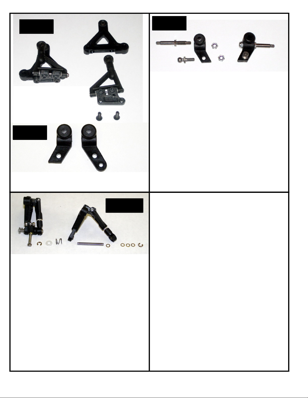
Locate the titanium front axles, four 4-40 alloy lock
nuts, and two alloy pivot balls.
Thread the titanium axles into the steering
spindles. Note that the threads on the axles that
go into the spindles are left hand. After the axles
are fully seated tighten an alloy 4-40 lock nut onto
the threaded stub coming out the back of the
spindle.
Thread the alloy pivot balls into the holes on the
steering arms and secure them with alloy 4-40 lock
nuts. Remember these are alloy pivot balls so
make the nuts snug. They are strong enough to
last a few racing seasons; but if you crank them
down, you can snap them.
Step 9
1. Snap an e-clip on to one end of the king pin.
2. Slide 3 shims onto the king pins against the
e-clip.
3. Pass this through the pivot ball in the upper
suspension arms rod end.
4. Place one more shim on the king pin.
5. Slide the steering spindle onto the king pin.
6. Slide the king pin through the pivot ball in the
lower suspension arm.
1. Slide the .020” spring and nylon retainer
onto the king pin and snap an e-clip on the
bottom of the king pin.
2. Repeat for the other side of the front
suspension.
Locate 2 steel 1/8” king pins,10 1/8” shims, 4 e-
clips and 2 .020” springs.
Special notes:
Make sure the steering arms on the spindle
are pointing towards the rear of the car as
shown in the picture.
The axle is offset in the spindle.
Make sure the axle is closest to the lower
suspension arm. As shown in the picture to
the left
It is important that the king pin slide
freely in all of the parts including the
steering spindle. When you thread the axle
into the spindle, it may swell the king pin
bore and make it tight on the spindle. You
can try to use a 1/8” drill to open it up but
the best solution is to use a 1/8” reamer.
You can order the reamer from:
www.mcmaster.com. The part number is
2995A61

Step 10
Locate four 8-32 x 5/8” screws and 4 nylon lower suspension arm spacer. Use 1 thin and 1 thick nylon spacer
under each pad on the arms.
Pass a screw through the chassis and slide a nylon riser over the screw. Start threading the screw into the
lower suspension arm but do not tighten it. Pass another screw through the chassis and slide a nylon riser over
that screw. Start threading the screw into the other hole on the lower suspension arm. Tighten both screws.
Repeat on the other side.
Special Note:
In testing, we found we preferred to not use any suspension brace, strap or tube to connect the left and right
suspension assemblies. This was true on high traction carpet tracks to low bite asphalt tracks. You can add
or remove lower arm spacers to adjust ride height and to compensate for tire wear.
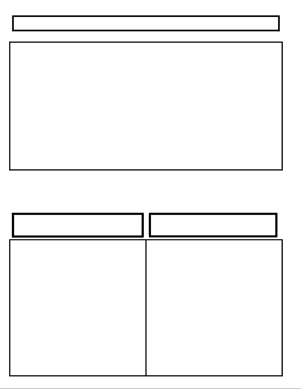
Locate two flex plates*, 2 flex plate pivot ball
housings w/ the pivot balls installed, and 4 2-56
button head screws.
1.Slide pivot ball housing through the flex plate so
the flex plate encloses the boss on the lower side of
the housing.
2.Pass the 2-56 screws through the pivot ball
housing from the top so they thread into the flex
plate.
Rear suspension assembly
Step 11

Step 12
Locate the delrin center pivot assembly, one 4-40 x
¼”, and two 4-40 x 3/8” flat head screws.
Attach the center pivot assembly to the rear most hole
in the center of the lower chassis plate with the ¼”
screw. The shoulder on the pivot ball and the two
bosses on the center pivot assembly should face
down towards the chassis. The pivot ball has a 3/32”
hex in the top so you can use a wrench to tighten it
firmly.
Attach the rear lower pod plate to the center pivot
assembly with two 4-40 x 3/8” flat head screws.
Take a minute to prepare all your carbon components
for assembly. With a file or sand paper knock off any
sharp edges along the perimeter or the carbon parts.
Special note:
Carbon fiber dust is really bad for you. Always
wear a mask and eye protection when sanding or
filing carbon fiber.
Step 13
Step 14
Attach the two flex plate assemblies to the lower pod
plate with 4-40 x 1/4: flat head screws. Access the
3/32” hex in the top of the pivot ball so you can tighten
it down firmly.
Locate 2 copper anodized non-threaded spacers, 2
copper anodized aluminum lock nuts and 2 4-40 x
½” flat head screws.
1.Pass a 4-40 x ½” flat head screw through the hole
in the chassis corresponding to the front hole on the
flex plate.
2.Pass a copper non-threaded spacer over the
screw.
3.Slide the forward hole on the flex plate over the
screw and the spacer.
4.Thread the aluminum locknut onto the screw and
hold it with a 3/16 nut driver as you tighten the
screw. You want these nuts to be tight but do not
overdo it. You do not want to strip the nuts.
5.Repeat to assemble the other side
Step 15

Step 16
Locate the two alloy rear pod plates, the alloy rear
pod plate spacer tube 2 4-40 x 3/8” flat head screws
and 4 4-40 x ¼” flat head screws.
Attach the alloy pod plates to the lower carbon pod
plate with the 4 4-40 x ¼” screws.
Attach the alloy rear pod plate spacer tube to the
allow rear pods with the 2 4-40 x 3/8” screws.
Step 18
Locate and install the two long copper anodized
threaded spacers as shown with 4-40 x ¼” flat head
screws.
Step 18
Locate and install the carbon damper tube/body
mount /brace as shown with 4-40 x ¼” flat head
screws.
Step 19
1. Apply 10,000wt silicon diff oil to the pistons
and insert them into the damper tubes.
2. Attach the alloy ball studs to the bottom of the
pod top plate and the tops pf the side wings as
shown in step 19. Secure them with alloy lock
nuts
3. Attach the carbon pod top plate to the alloy
rear pod plates
4. Snap the ball cups of the assembled damper
tubes onto the pivot balls on the pod top plate
and cross brace.
Note:
If you feel play between your ball cups and ball
studs, you can place a single layer of plastic
bag material between your ball cup and ball
stud then snap them together. This will cut
and insert a disc of plastic into your ball cup
reducing or eliminating the play. If you still
feel play, repeat the process. We find you
usually need one to two layers to get the
proper feel, no play but totally free movement.
Locate the damper tube parts bag, the rear pod top
plate and 4 4-40 x ¼” flat head screws..
1.Thread a 4-40 x 3/8” set screw into each of the 4
ball cups from the damper parts bag.
2.Thread a ball cup/set screw assembly into the
ends of each of the damper tube pistons and
damper tubes.

Step 20
1. Install the molded shock mount-antenna mount
with 2 4-40 x 1/4” flat head screws using the 2 rear
mounting holes.
2. Assemble the Silva bladder shock as per the
included instructions with 50wt silicon shock oil.
3. Place the one medium black alloy ball stud in the
antenna mount and a standard ball stud in the rear
pod top plate as shown. Secure the top pod plate
ball stud with an alloy lock nut.
4. Install the included gold shock spring onto the
shock and snap the shock in place.
Trim the ball cup so the over all shock length is 2.710” .
This length will give you the standard setting of 1.5mm
of rear pod droop. If you thread on the ball cup until it
stops, you will have zero pod droop.
Diff Assembly:
1. Put a small dab of diff grease on the axle flange
so the diff will stick to it. Place a diff ring on the
flange so its flat keys onto the flat on the diff
flange.
2. Place a flanged 3/8 x ¼” bearing in the center
of the spur gear. Slide the spur gear and
bearing unit on to the axle until it stops against
the diff ring.
3. With a small flat screw driver remove the diff
balls from the diff grease and snap them into
the outer row of holes in the spur gear.
4. Place a flanged 3/8 x ¼” bearing into the inside
face of the right side diff hub. Put a small dab of
diff grease on the hub flange so the diff will
stick to it. Place a diff ring on the flange so its
flat keys onto the flat on the hub flange. Slide
this unit on to axle.
5. Slide a flanged 3/8 x ¼” bearing over the axle
into the outside face of the right side diff hub.
Slide the stepped thrust cone onto the axles so
the smaller diameter part is against the right
hub bearing.
Locate the rear axle parts bag. There are a couple
of steps that can make your diff last longer that should be
done at this time.
Use the right alloy diff hub as a holder and sand
both sides of each diff ring on 600 grit sand paper using
electric motor cleaner spray as a lubricant. Sand until you
see an even scoring pattern across the face of each diff
ring. Clean them with motor spray and set them aside.
The diff balls may have a protective oil coating on
them. Place them on a clean paper towel and carefully
clean them with motor spray. When dry drop them into
your cup of diff grease and stir them to coat them with diff
grease.
Step 21
Step 21 Continued
1. Thread the black nylon lock nut onto the
threaded stud on the axles until it makes
contact with the thrust cone.
2. Tighten the black lock nut gradually with an
11/32” nut driver until you notice you cannot slip
the spur gear when holding the axle and right
hub in a fixed position.
Six 4-40 x ¼” cap head screws are supplied to mount
your rear wheels.
Notes:
Keep you fingers clean with motor spray. Diff
assembly is like surgery. You do not want dirt
or oil where it does not belong.
The grease on the diff balls when you pluck them out
of the cup of diff grease is all you need.
Smearing diff grease on the rings will make
your diff get dirty faster and make a mess.
The ultimate goal in building a diff is one which is
extremely free and glass smooth but requires a
lot of force to slip the spur gear.

Insert the IRS precision ride height adjuster cams into
the rear alloy pod plates. Insert a 3/8” x ¼” flanged
bearing into each ride height adjuster and insert the
axle as shown. Note that the left clamping hub has
the shallow center boss out towards the wheel. This
is necessary to have symmetrical wheel spacing.
Install your favorite wheels and measure the width of
the car. Shim as necessary to obtain a centered axle
and a 172mm rear track width.
Special Note:
The Copperhead 12 is designed to work with IRS
precision ride height adjuster cams. We find too
much size variation in other cams and cannot
guarantee they will fit properly.
Step 22
For most conditions we run the servo on the
angled mounts.
Step 23
Step 24
If you are looking to run the servo flat, you will need to
use black medium ball studs on the steering spindles
to remove bump steer. This form of servo mounting
will give the effect of being more smooth and easier
to drive.
You have two servo mounting options with the
Copperhead 12, Angled or Flat. The BMI Servo
Mounts have holes to allow either mounting option.
The servo is mounted to the servo mounts with two
4-40 x ¼” button head screws.

You will need to secure battery with strapping tape.
Congratulations, your done!
Go to the starting setup sheet, adjust your car to
the base setup and hit the track!
Step 25
Step 26
Step 27
The Servo mounts are attached to the lower chassis
with two 4-40 x ¼” flat head screws.
At this time drill out the center holes on your servo
saver (not supplied) for two Nickel Teflon ball studs.
Secure them with two 3/16 alloy lock nuts.
You have two slotted holes for servo mounting in the
chassis and 2 in each servo mount. They let you
achieve proper linkage geometry whether you run
your ball studs in front of the servo saver as shown or
behind them. The slots in the chassis allow you to
center your servo. The chassis is not limited to fitting
specific servos. Any mini servo will fit. This is a
valuable tuning option as the servo’s weight has a big
effect on chassis weight distribution.
Locate two titanium turnbuckles and four black ball
cups. Assemble them as shown and adjust them to
an over all length of 2.375” (60.5mm). This is a
starting point. You will need to reset their length after
setting your camber in order to achieve the desired
amount of front toe.
Note:
You can use the same plastic bag trick mentioned in
Step 19 to remove play in your steering linkage.
Remember you want to remove play but still have
totally free movement in the links. Any friction at all is
unacceptable and will make you car not center
properly after steering inputs
Install your body posts with two 4-40 x 3/8” flat head
screws in the front and two 4-40 x ¼” button head
screws in the rear..
Step 28

Copperhead 12 1/12 Pro (LiPo) Racing Chassis Kit
Includes:
(1) #DBB1011R LiPo CHASSIS PLATE or (1) DBB1010R CHASSIS PLATE
(1) #DBB1020R LOWER POD CF
(1) #DBB1030R TOP REAR POD PLATE
(1) #DBB1141 CROSS BRACE
(1) STICKER SHEET
(1) #DBB7010 BOCA 1/4 X 3/8 FLANGED BEARING PAIR (5)
(1) #DBB7020 BOCA 1/8 X 5/16 FLANGED BEARING PAIR (4)
(1) #DBB1110 FIBERGLASS ROLL OVER ANTENNA
(1) #DBB6105 10-32 X 1/8 SET SCREWS PAIR (2)
(1) #DBB6215 2-56 X 3/16 BUTTON HEAD SCREWS (4)
(1) #DBB6225 2/56 X 3/16 FLAT HEADS PAIR (2)
(1) #DBB6411 4-40 X 1/4 FLAT HEAD SCREWS (17)
(1) #DBB6412 4-40 X 3/8 FLAT HEAD SCREWS (8)
(1) #DBB6413 4-40 X 1/2 FLAT HEAD SCREWS (6)
(1) #DBB6435 4-40 X 1/2 SET SCREWS PAIR (2)
(1) #DBB6445 4-40 X 1/4 CAP HEAD SCREWS (6)
(1) #DBB6465 4-40 X 1/4 BUTTON HEAD SCREWS (8)
(1) #DBB6485 ALLOY LOCK NUT (14)
(1) #DBB6495 NICKLE/TEFLON BALL STUD SET (8)
(1) #DBB6496 MEDIUM BALL STUD (1)
(1) #DB6510 King Pin E-Clips (4)
(1) #DBB4010R REAR AXLE KIT
(1) #DBB4030 IRS RIDE HEIGHT ADJUSTER SET
(1) #DBB4040 REAR AXLE SHIMS (6)
(1) #DBB5088 88T/64P DIFF. GEAR
(1) #DBB3010R FLEX PLATES G10 PAIR (2)
(1) #DBB3020 CENTER PIVOT BALL HOUSING & BALL
(1) #DBB3025 REAR SUSPENSION PIVOT BALLS PAIR (2)
(1) #DBB3029 FLEX PLATE PIVOT BALL HOUSING PAIR (2)
(1) #DBB3040 DAMPER TUBE ASSY. PAIR
(1) #DBB3056 MICRO SPRING GOLD 12#
(1) #DBB3060 SILVA BLADDER SHOCK

(1) #DBB2010 IRS LOWER SUSPENSION ARMS, SPACERS & SCREWS
(1) #DBB2020 FRONT UPPER SUSPENSION ARM MOUNT SET
(1) #DBB2025 UPPER SUSPENSION ARMS PAIR (2)
(1) #DBB2030 FRONT UPPER SUSPENSION ARM ROD END PAIR (2)
(1) #DBB2035 FRONT UPPER SUSPENSION ARM TURNBUCKLE PAIR (2)
(1) #DBB2040 IRS UPPER HINGE PIN SET (2)
(1) #DBB2050 FRONT SUSPENSION PIVOT BALLS (4)
(1) #DBB2060 STEERING SPINDLE PAIR (2)
(1) #DBB2065 TITANIUM FRONT AXLE SET W/NUTS (2)
(1) #DBB2070 KING PIN PAIR (2)
(1) #DBB2075 KING PIN SHIMS (10)
(1) #DBB2080 TITANIUM TURNBUCKLES PAIR (2)
(1) #DBB2100 LINEAR FRONT SPRINGS W/CUP .020 PAIR (2)
(1) #DBB1053R REAR POD BRACE
(1) #DBB1054R LOWERED RIGHT POD PLATE
(1) #DBB1055 LOWERED LEFT POD PLATE
(2) #DBB1060 SERVO MOUNTS PAIR (2)
(1) #DBB1070 STAND OFF SET
(2) #DBB1080 BODY MOUNTS PAIR (2)
(1) #DBB1081 BODY MOUNT PIVOT (4)
(1) #DBB1082 BODY PINS (8)
(1) #DBB1091 BATTERY RETENTION BELT
(1) #DBB1092 ANTENNA/SHOCK MOUNT
(1) #DBB1093 BALL CUP (12)
(1) #DBB1094 FIBERGLASS BATTERY LOCATOR PLATE (ONLY IN LiPo KIT)
This manual suits for next models
3
Table of contents
Other BMI Racing Motorized Toy Car manuals