BMS SOLANO 50 RX User manual

BMS SOLANO 50 RX
OWERN’S MANUAL

TABLE OF CONTENTS
2
Precautions.......................................................................... 7
SIDE VIEW........................................................................ 9
CONTROLSAND INSTRUMENTS............................. 10
VEHICLE IDENTIFICATION NUMBER (VIN).........11
MAIN SWITCH............................................................... 12
Lock the steering ..................................................12
Unlock the steering...............................................12
DASHBOARD UNIT....................................................... 12
HANDLEBAR SWITCHES - LEFT.............................. 13
HANDLEBAR SWITCHES /R....................................... 13
BRAKE LEVER............................................................... 14
FUELTANK CAP............................................................ 14
Remove the fuel tank cap.....................................14
Install the fuel tank cap........................................15
FUEL..................................................................................15
CATALYTIC CONVERTER...........................................15
KICK STARTER..............................................................15
To close the seat.....................................................16
FRONT HOOK, HELMET.............................................17
SIDE STAND.....................................................................17
MAIN STAND...................................................................17
PRE-OPERATION CHECK LIST.................................19
STARTING THE ENGINE..............................................20
Starting with the electric starter.........................20

TABLE OF CONTENTS
3
Starting with the kick starter..............................21
STARTING OFF.............................................................. 21
ACCELERATION / DECELERATION........................ 21
BRAKING......................................................................... 21
PARKING......................................................................... 22
ENGINE BREAK IN....................................................... 23
OWNER’S TOOL KIT ................................................. 23
BATTERY......................................................................... 24
SPARK PLUG .................................................................. 24
Check the spark plug ...........................................24
ENGINE OIL.................................................................... 26
FINALTRANSMISSION OIL....................................... 27
Change the final transmission oil........................27
AIR FILTER......................................................................27
Replace the air filter.............................................28
THROTTLE CABLE FREE PLAY................................28
TIRES ................................................................................28
Tire air pressure....................................................29
Tire inspection.......................................................29
RIMS..................................................................................30
BRAKE LEVER FREE PLAY........................................30
BRAKE PADS...................................................................31
Brake pads - Front................................................31
Brake shoes - Rear................................................31
BRAKE FLUID.................................................................32
Changing the brake fluid.....................................32

TABLE OF CONTENTS
4
CABLES............................................................................ 33
THROTTLE GRIPAND CABLE.................................. 33
Front brake lever..................................................33
Rear brake lever...................................................33
SIDE STAND / MAIN STAND ....................................... 33
FRONT FORK................................................................. 34
STEERING....................................................................... 34
WHEEL BEARINGS....................................................... 35
BATTERY......................................................................... 35
Charge the battery................................................35
Store the battery...................................................35
FUSE.................................................................................. 36
Replacing the fuse.................................................36
LIGHTING........................................................................36
TROUBLESHOOTING CHART....................................37
TROUBLESHOOTING CHART....................................38
CLEAN THE VEHICLE..................................................39
Before cleaning......................................................39
Cleaning after normal use....................................39
Cleaning after riding in the rain, near ...............39
the sea or on salt-sprayed roads..........................39
After cleaning........................................................40
STORAGE.........................................................................40
PERIODICAL MAINTENANCE SCHEDULE............42
Specification ......................................................................44
IMPORTANT INFORMATION .....................................45

Operating Instructions USER’S MANUAL
5
Thanks for your purchasing of this vehicle. This model is designed for safety, built for durability, and
perfected for daily street use. The unique vehicle design, enrich of stylish and personality, represents your
outstanding taste and favor to pursue the state of the art living attitude.
This manual describes the correct usage of this motorcycle including safety riding, simple inspection methods and so on.
For a more comfortable and safety riding, please read this manual carefully. If any questions concerning the operation or
maintenance of your vehicle, please consult a dealer.
USER’S MANUAL Operating Instructions
6
In this manual with some important information is distinguished by the following notations:
Is a WARNING which has to be followed. Refusing to follow can lead to severe injury or death to the operator.
A CAUTION indicates a important information to avoid damage to the vehicle.
•Please always put this manual with vehicle for rider maintenance/ dealer tracking of service records even if vehicle is
being sold.
•This manual contains the most of the vehicle information, however, the maker will continually improve it’s product
design and quality that lead to difference between the manual and vehicle . If you have any questions concerning this
manual, please consult your dealer.
FOR YOUR OWN SAFETY, PLEASE READ THIS MANUAL CAREFULLY BEFORE OPERATION THIS
VEHICLE. ONLY OPERA TE THE VEHICLE UNTIL YOU HAVE COMPLETELY AWARE OF ADEQUATE
KNOWLEDGE OF CONTROLS AND OPERATION.
FEATURE AND YOU HAVE BEEN TRAINED IN SAFE AND PROPER RIDING TECHNIQUES. PERIODIC
INSPECTIONS, WELL
MAINTENANCE AND GOOD RIDING SKILLS, WILL ENSURE YOUR SAFETY RIDING AND INCEASE THE
PRODUCT RELIABI LITY OF THIS VEHICLE.

Operating Instructions USER’S MANUAL
7
Precautions
* Please observe traffic laws and regulations carefully and drive safely.
*Make sure not to lend this motorcycle to be driven by a person not holding a driver’s license.
*Make sure not to hang anything on the direction handgrip, otherwise the driving safety may be affected.
*Please wear your protective articles such as helmet, dust goggles, gloves for the sake of your safety.
*Make sure not to use this model to participate in any kind of competition. Otherwise, any mechanical breakdown,
injury or death arising where from shall be on your own account.
* The temperature of exhaust silencer is high when the motorcycle is running. Drivers shall be careful not to touch it to
burn them.
*Don’t wear loose clothes or slippers when driving it. Otherwise, it may hook the control grip and accessories, and thus
cause potential safety hazards.

USER’S MANUAL Operating Instructions
8
* After opening the packaging box, please check the accessories and various documents delivered with the motorcycle
according to the packing list.
* The motorcycle accommodates two persons, and the maximum payload is 150 kg. The moped accommodates 1 person,
and the maximum payload is 75 kg.
* It is not allowed to modify any part of the motorcycle. Otherwise, the reliability, stability and comfortableness of the
motorcycle may be affected.
* Only the fuel with a grade specified on the fuel tank or above can be used. Otherwise, the dynamic performance,
economy, and safety of the motorcycle may be damaged, and the service life of the motorcycle will be shortened. If any
mechanical breakdown occurs due to this, you shall be solely responsible for it.
* This Manual is a necessity for the use of the motorcycle. If the motorcycle is transferred to any other person, this
Manual should be transferred together with the motorcycle.
* When it is necessary to adjust the air valve clearance of the motorcycle, please do it in a professional motorcycle
maintenance shop or in a designated after-sales service center.

Operating Instructions USER’S MANUAL
9
SIDE VIEW
1. Front wheel
2. Front disc brake
3. Front turn signal light
4. Headlight
5. Helmet holder
6. Fuel tank cap
7. Seat
8. Storage compartment
9. Battery
10. Tail/brake light
11. Rear turn signal light
12. Muffler
13. Rear wheel
14. Rear drum brake
15. Air filter
16. Kick starter
17. Main stand
18. Passenger footrest
19. Side stand
USER’S MANUAL Operating Instructions
10
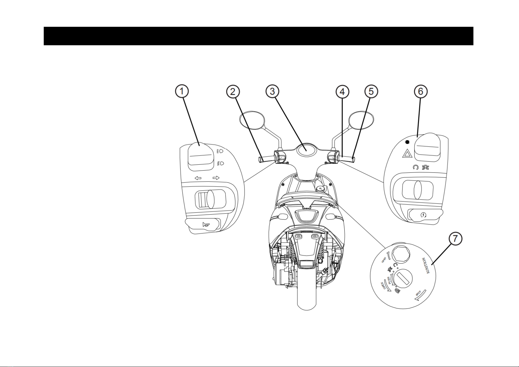
CONTROLS AND INSTRUMENTS
1. Left handlebar switches
2. Rear brake lever
3. Dashboard unit
4. Front brake lever
5. Throttle grip
6. Right handlebar switches
7. Main switch

Operating Instructions USER’S MANUAL
11
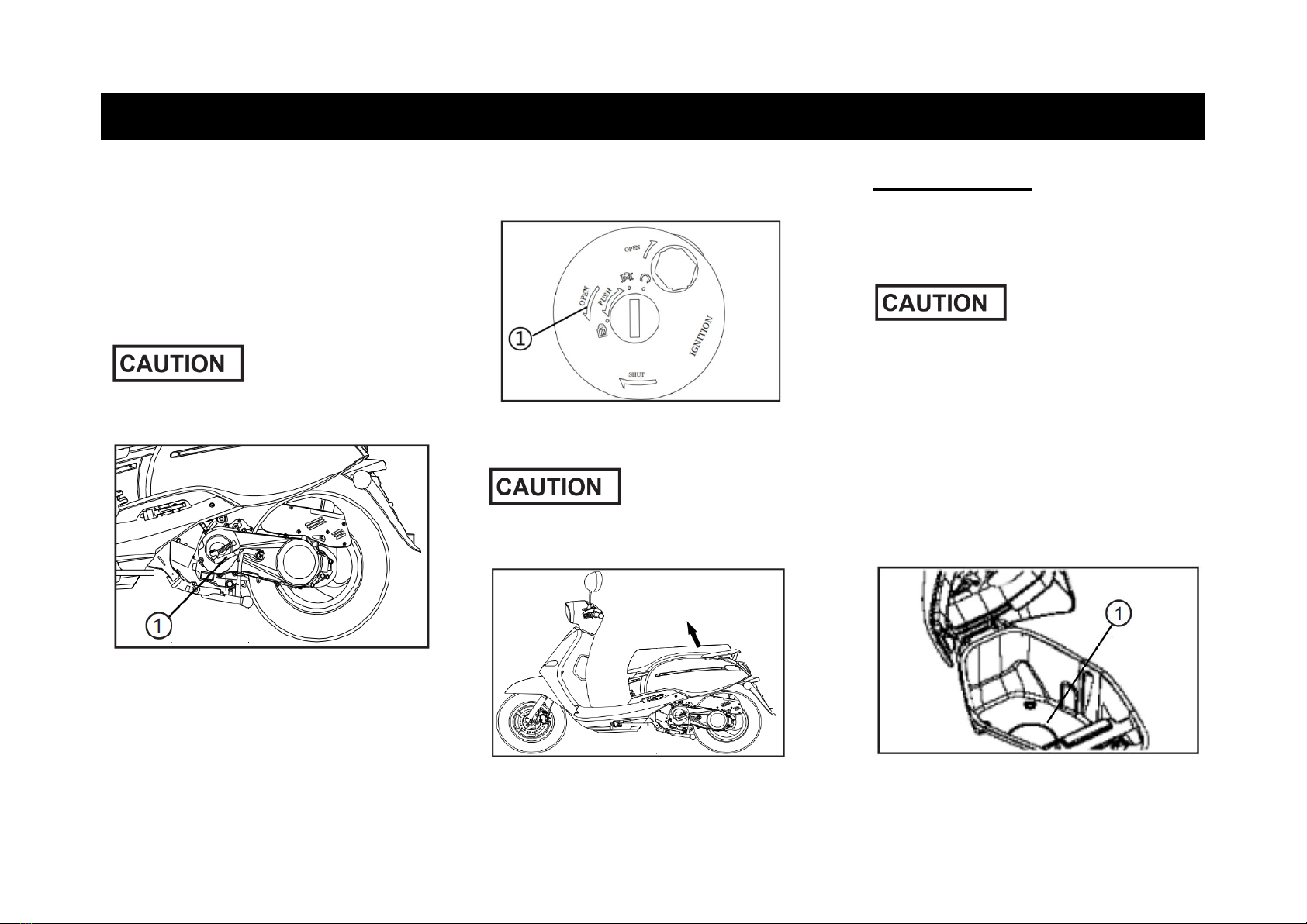
VEHICLE IDENTIFICATION NUMBER (VIN)
Please write down the VIN (vehicle identification number) to order replacement parts from your dealer or the vehicle should
be stolen.
The chassis number is stamped into the frame. To see this, take the cover (1) from the inner lining in the foot.
The vehicle identification number is used to identify your motorcycle and may be used to register your vehicle with the
licensing authority in your area.

USER’S MANUAL Operating Instructions
12
MAIN SWITCH
The main switch controls the ignition
and lighting systems, and also used to
Lock the steering. The various
positions are described as below.
On
All electrical circuits are supplied with
power, the engine can be started. The
key cannot be removed.
Off
All electrical systems are off . The key
can be removed.
Steering lock
The steering is locked, and all
electrical systems are off. The key can
be removed.
Lock the steering
1. Turn the handlebar fully to the left.
2. Insert the key into the main switch.
3.Turn the key while you apply
pres-sure to it, counterclockwise in the
position. If the lock does not engage
immediately, move the handlebars
back and forth slightly.
4. Remove the key.
Unlock the steering
1. Insert the key into the main switch.
2. Turn the key clockwise to the
position. If the lock does not engage
immediately, move the handlebars
back and forth slightly.
Never turn the key to or , while
the vehicle is moving, otherwise the
electrical systems will be switched
off, which may result in loss of
control or an accident. Make sure
that the vehicle is stopped before
turning the key.
Open the glove compartment
When in „OFF“position, turn the key
counterclockwise without pushing it in
to open the glove compartment.
DASHBOARD UNIT
1. Turn signal indicator light /
2. High beam indicator lamp
3. Engine warning light (EOBD)
4. Odometer
Operating Instructions USER’S MANUAL
13
5. Speedometer
6. Fuel warning indicator
1. Turn signal indicator light /
This indicator light flashes when the
turn signal light is activated.
2. High beam indicator lamp
Lights up whenever high beam is
switched on.
3. Engine warning light (EOBD)
When you turn on the ignition, the
lamp lights up. After starting the
engine, it disappears. If your vehicle
detects a failure in the system, the
check engine lamp lights up(EFI
SYSTEM only have this function).
4. Odometer
The dashboard unit is equipped with
an odometer. The odometer shows the
total distance traveled.
5. Speedometer
The dashboard unit is equipped with a
speedometer. The speedometer shows
the riding speed.
6. Fuel warning indicator
The fuel warning indicator shows if you
have little fuel left in the tank. Refuel
immediately.
The fuel gauge indicates the amount of
fuel in the fuel tank. The needle moves
towards „E“(Empty) as the fuel level
decreases.
Be take care not let the fuel tank to fully
empty it-self, that cause engine can not
run it-self anymore.
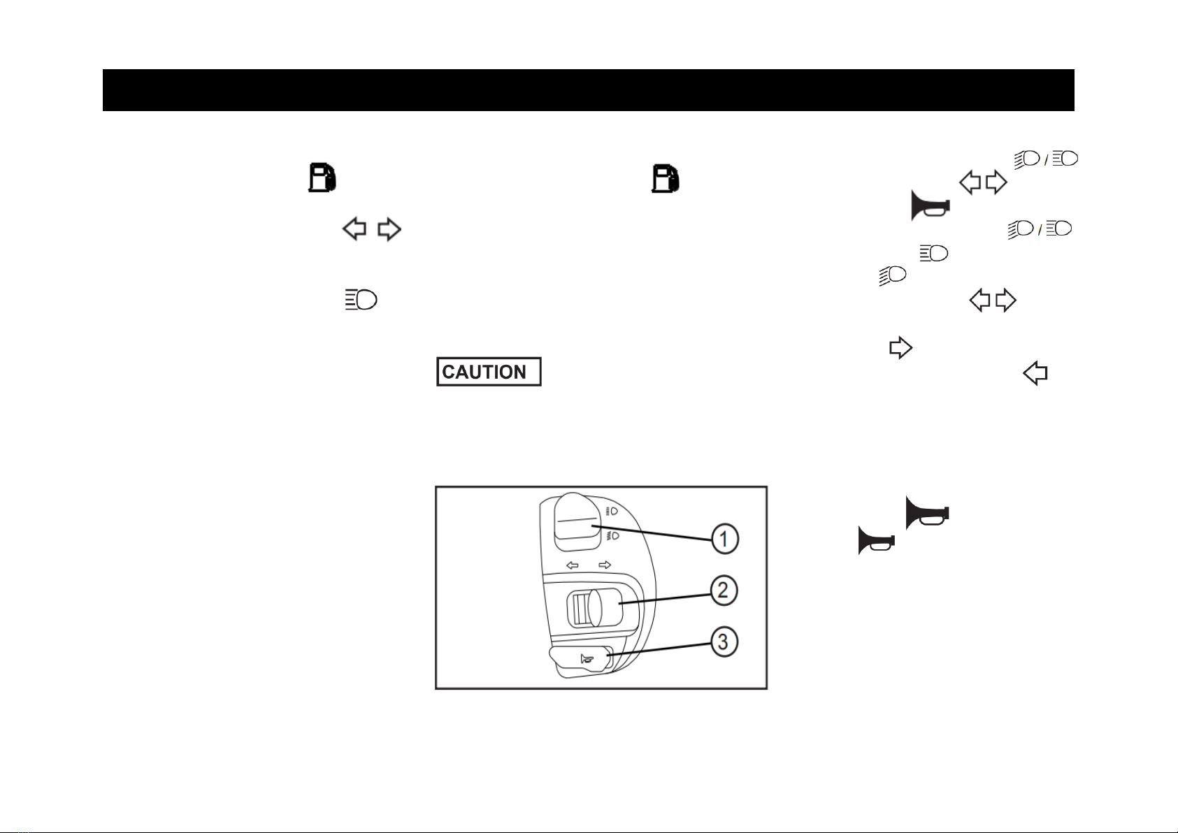
HANDLEBAR SWITCHES - LEFT
1. High / Low beam switch
2. Turn signal switch
3. Horn switch
1. High / Low bean switch
Set this switch to for the high
beam and to for the low beam.
2. Turn signal switch
To signal a right-hand turn, push
this switch to . To signal a left
hand turn, push this switch to .
When released the switch returns to
the center position. To cancel the
turn signal lights, push the switch in
after it has returned to the center
position.
3. Horn switch
Press this switch to sound the
horn.
USER’S MANUAL Operating Instructions
14
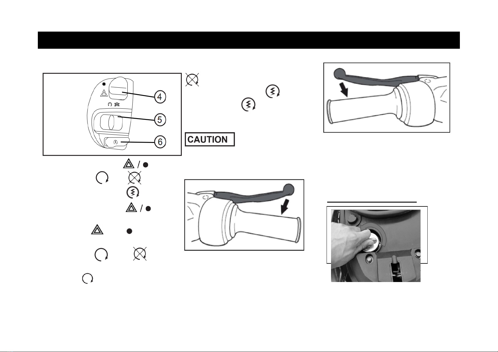
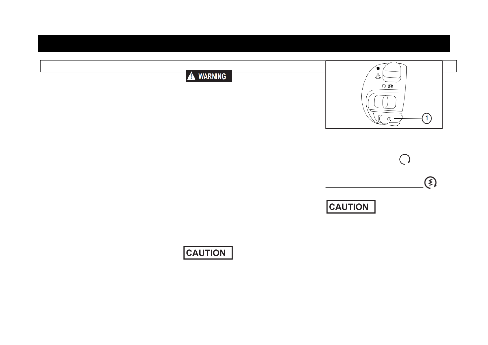
HANDLEBAR SWITCHES /R
4. Warning light switch
5. Engine - ON /OFF
6. Electric starter switch
4. Warning light switch
By changing the switch position you
can switch on or off the warning
light.
5.Engine - ON /OFF
The power switch is “ON”and ignition
switch is at position, at the mean-time,
grip the brake, the engine can be
started. And press engine off switch at
position, the engine is will be off.
6. Electric start switch
Push this switch (pull the brake
lever at same time) to the start the
engine.
Before starting the vehicle check the
notes in the user manual.
BRAKE LEVER
The front brake lever is located on the
right handlebar grip. To apply the front
brake, pull this lever toward the
handlebar grip.
The rear brake lever is located on the
left handlebar grip. To apply the rear
brake,pull this lever toward the
handlebargrip.
FUELTANK CAP
Remove the fuel tank cap
Turn the fuel tank cap counterclockwise.
Now you can remove the fuel tank
cap.

Operating Instructions USER’S MANUAL
15
Install the fuel tank cap
Push the fuel tank cap into position.
Turn the cap clockwise to the original
position.
Make sure that the fuel tank cap is
properly closed and locked before
riding.
FUEL
Make sure that there is sufficient fuel in
the tank. Fill the fuel tank to the bottom
of the filler tube as shown.
•Do not overfill the fuel tank,
other-wise it may overflow when the
fuel warms up and expands.
•Avoid spilling fuel on the hot engine.
Immediately wipe off spilled fuel with
a clean, dry, soft cloth, since fuel may
damage the painted surfaces or plastic
parts.
CATALYTIC CONVERTER
This model is equipped with a catalytic
converter in the exhaust system.
The exhaust system is hot after
operation. Make sure that the
exhaust system has cooled down
before doing any maintenance work.
The following precautions must be
observed to prevent a fire hazard or
other damages.
•Use only unleaded gasoline. The
use of leaded gasoline will cause
unrepairable damage to the catalytic
converter.
•Never park the vehicle near possible
fire hazards such as grass or other
materials that easily burn.
•Do not allow the engine to idle too
long.
USER’S MANUAL Operating Instructions
16
KICK STARTER
To start the engine with the kick starter
(1) , move it down lightly with your
foot until the gears engage, and then
push it down smoothly but forcefully.
At the same time you have to pull the
right brake lever to start the vehicle.
SEAT
1. Place the vehicle on the center stand.
2. Insert the key into the seat lock (1),
and then turn the key clockwise to
“OPEN”the seat.
Do not push inward when turning the
key.
3. Fold the seat up.
To close the seat
1. Fold the seat down, and then push it
down to lock it in place.
•When you close the seat by force
or strike, parts can be damaged.
•Make sure that the seat is locked
before driving or when you park the
vehicle.
STORAGE LUGGAGE BOX
There storage luggage box (1) is under
the seat.

Operating Instructions USER’S MANUAL
17
•Do not exceed the load limit of 2.5
kg for storage luggage box (1).
•Since the storage luggage box will
accumulates heat by the heat of sun
and engine, please do not put any thing
that sensitive to the heat.
•Do not put anything valuable or
Breakable objects in the storage
luggage box.
FRONT HOOK, HELMET
Do not exceed the load limit of 1
kg for the front Hook (1).
SIDE STAND
The side stand (1) is located on the left
side of the vehicle. Release the side
stand by using your feet to step on the
bracket of side stand to up-right
position to stand the vehicle.
•Please avoid to use side stand to
park the vehicle on the slope, soft
land or uneven ground .
MAIN STAND
The main stand (1) is located under
the vehicle. Release the main stand by
using your feet to step on the bracket of
side stand to up-right position to stand
the vehicle.
The main stand with auto-rebound
system. Make sure your vehicle have

Operating Instructions USER’S MANUAL
18
been park well are stable enough to stand the vehicle.
The condition of a vehicle is the owner’s responsibility. The operator should check the vehicle by simple but thorough
inspection,to make sure of vehicle condition, quick inspect some key and important parts, to prevent the vehicle from serious
consequence /accident. Please carefully check the following points before each ride.
The condition of a vehicle is the owner’s responsibility. The operator should check the vehicle by simple but thorough
inspection,to make sure of vehicle condition, quick inspect some key and important parts, to prevent the vehicle from serious
consequence/accident. Please carefully check the following points before each ride.
If any item in the Pre-operation check list is not working properly , have it inspected and repaired before operating
the vehicle. If failed to be corrected by yourself, please turn to repair shop immediately.
If failed to be corrected by yourself, please turn to repair shop immediately.

USER’S MANUAL Operating Instructions
19
PRE-OPERATION CHECK LIST
CHECKPOINT
TO VERIFY
Fuel
•Check fuel level in fuel tank.
•Refuel if necessary.
•Check fuel line for leakage.
Engine oil
•Check oil level in oil tank.
•If necessary, add recommended oil to specified level.
•Check vehicle for oil leakage.
Final transmission oil
•Check vehicle for oil leakage.
Front brake
•Check operation.
•If soft or spongy, have dealer bleed hydraulic system.
•Check brake pads for wear.
•Replace if necessary.
•Check fluid level in reservoir.
•If necessary, add recommended brake fluid to specified level.
•Check hydraulic system for leakage.
Rear brake
•Check operation.
•Lubricate cable if necessary.
•Check lever free play.
•Adjust if necessary.
Throttle grip
•Make sure that operation is smooth.
•Check cable free play.
•If necessary, have dealer adjust cable free play and lubricate cable and grip housing
Wheels and tires
•Check for damage.
•Check tire condition and tread depth.
•Check air pressure.
Brake levers
•Check for damage.
•Check tire condition and tread depth.
•Check air pressure.
Main stand
•Make sure that operation is smooth.
•Lubricate pivot if necessary.
Chassis fasteners
•Make sure that all nuts, bolts and screws are properly tightened.
•Tighten if necessary.
Operating Instructions USER’S MANUAL
20
Instruments, lights, signals and switches
•Check operation, correct if necessary
•Before riding the vehicle, please
make sure that you are fully familiar
with all operating controls their
functions before riding. To consult a
dealer shop if you not thoroughly
understand.
•Please do not start the engine in
a closed area, the exhaust air are
poisonous, and inhaling them can
cause loss of consciousness and
even death in short time.
STARTING THE ENGINE
Note the point „Engine break in
“before you start to riding the
vehicle.
Starting with the electric starter
1. Turn the key to ON .
2. Pull the right brake lever otherwise
the vehicle will not start.
3. Push the start switch button (1)
for a few seconds.
•Do not crank the engine more than 5
seconds on any one attempt.
•The engine starts immediately upon
actuation of the starter, then wait a
Table of contents
Other BMS Scooter manuals


