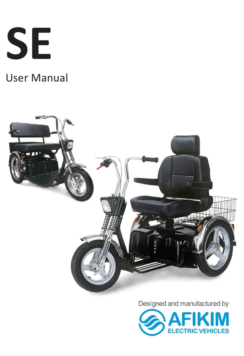
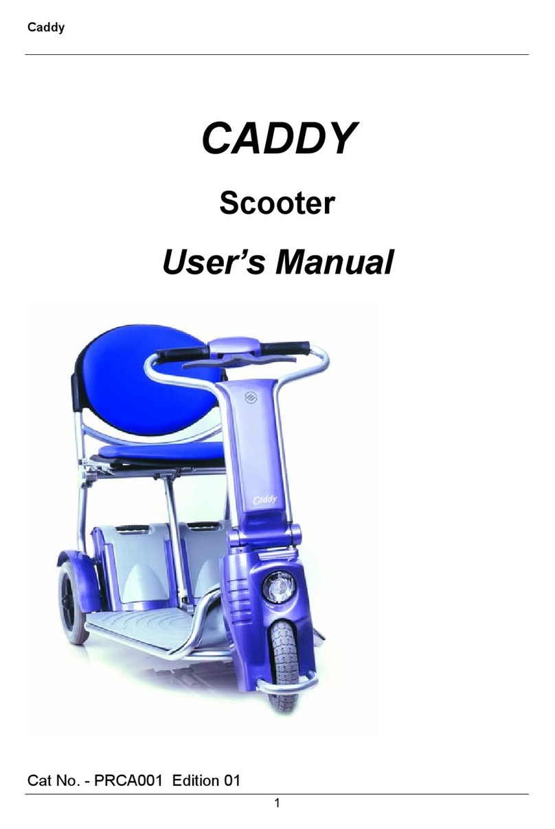
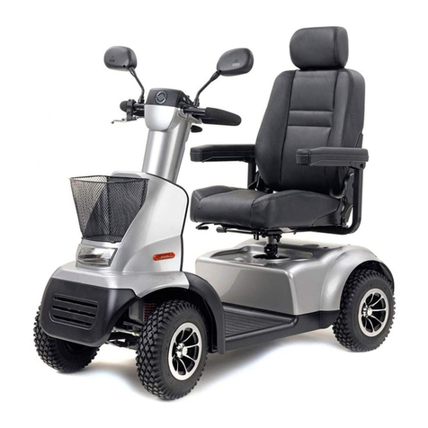
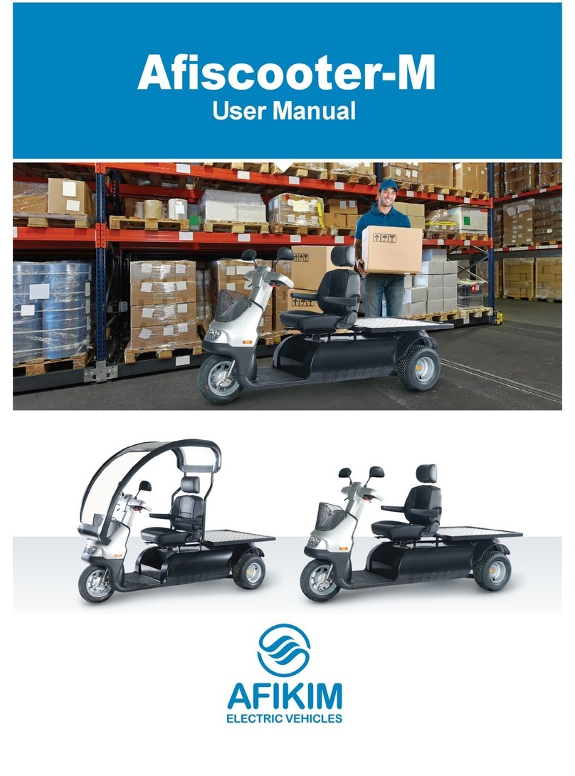
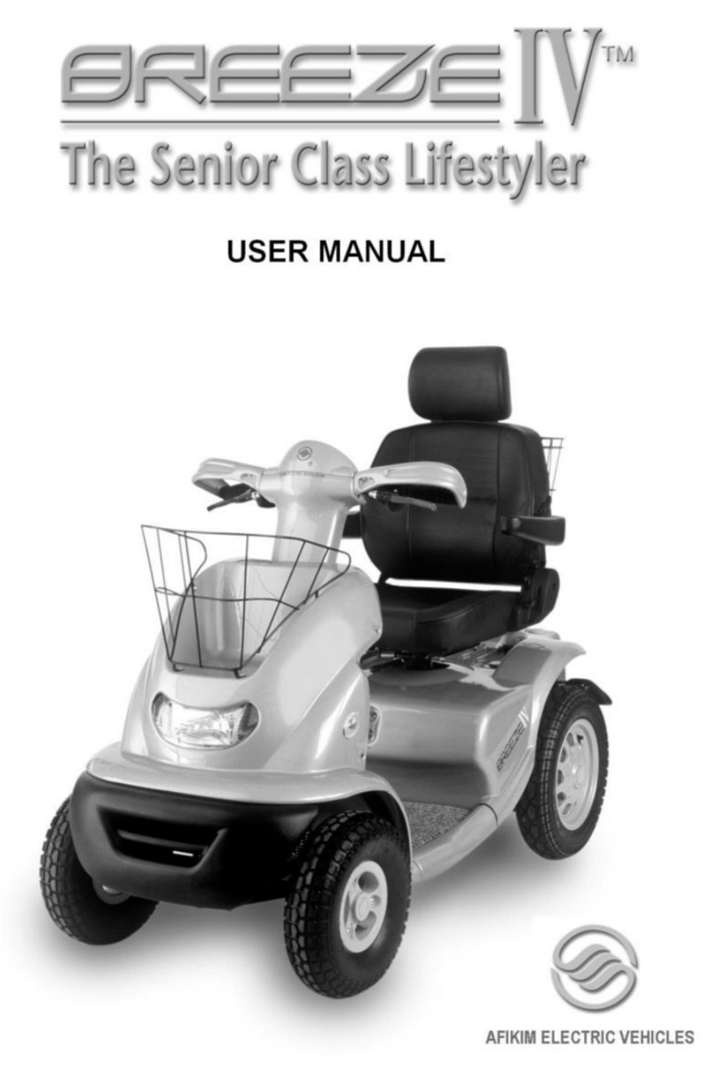
Afikim Breeze User manual

Important Notes :
1- Prior to using this file you should have an Acrobat Reader Software revision 3 or
higher , installed on your PC machine , that will allow you to view and print the
drawing files .
2- Acrobat Reader Software is free , and can be installed from the CD application.
3- If files are copy into a Hard disk ,the all 37 files should be copied into one
Subdirectory .
4- The Follows sign will always take you back to the main menu :
5- To go to menu press : TABLE OF CONTENTS
Breeze
Maintenance Manual
Afikim Electric Mobilizer
Kibbutz Afikim 15148, Israel
Tel.: 972- 4-6754814
Fax : 972-4-6751456
Customer Service : 972-4-6754180
Website: www.afiscooters.com p/n – PRBR003

2
November 2003
Revision : 03
Product: Breeze - all models
Warning
Please read this manual carefully before engaging in any maintenance operations of the
Breeze. If you have any questions about the contents of this manual, please do not
hesitate to call the company for clarification.
Maintenance operations should be carried out only by authorized technicians of Afikim
Electric Vehicles or its representatives.
Remember - any product which does not functional properly may cause harm to either
property or persons.
Warning
Electro-Magnetic Interference may cause the vehicle to perform in an unanticipated
manner, endangering the user. For your safety, before using the Breeze, it is strongly
recommended to read Chapter 4 "Electro-Magnetic Interference " carefully.
The serial number and manufacturer details are on a label adjacent near the cellular cabin
.

3
TABLE OF CONTENTS
Chapter 1 – Maintenance 1
1.1 General and Safety Instructions to the Technician 1.1
1.2 List of Recommended Tools for a technician 1.2
1.3 Periodic Maintenance 1.3
1.4 Handling (Wet) Batteries 1.4
1.5 Basic Cleaning of the Breeze 1.5
1.6 Shock Absorbers Adjusting to the User Weight 1.6
Chapter 2 –Troubleshooting and General Faults Repairing 2
Chapter 3 - Electrical and Electronic Systems 3
3.1 Main Electric Wiring Diagram 3.1
3.2
Main Electric and Electronic System Description 3.2
3.3 Troubleshooting Electric and Electronic Faults 3.3
3.3.1 General instructions for Electric troubleshooting 3.3.1
3.3.2
Troubleshooting Electric and Electronic Faults 3.3.2
3.3.3
Troubleshooting Charging Problems 3.3.3
3.3.4
Voltage supply measurements 3.3.4
3.3.5 No Load Test and Driving Test 3.3.5
3.3.6 Potentiometer Tests and Calibration 3.3.6
3.3.7 Status Indicator - Fault Diagnosis 3.3.7
3.3.8 Programmer SP-1 Fault Diagnosis 3.3.8
3.4 Controller Parameters Set-Up 3.4
3.5
Front Board Alarms / Horn Dip switches Adjusting 3.5
3.6
SP-1 Programmer Manual 3.6
3.7 SOLO 130A Controller Manual 3.7
3.8 True Charge Battery Gauge Manual 3.8
Chapter 4 – EMI Warnings 4
Appendix A - List of Recommended Spare Parts/Assemblies A
Appendix B - Exploded Drawings of Parts and Assemblies B

4
CHAPTER 1 – MAINTENANCE
1.1 GENERAL AND SAFETY INSTRUCTIONS TO THE TECHNICIAN
Warnings
1. When handling the Breeze mechanical systems such as the motor, transaxle, wheels and
electro-magnetic unit, the main supply should be disconnected by removing the battery
cables in order to prevent accidental operation.
2. When conducting electrical tests, elevate the rear wheels using a jack or stable block of
wood. Avoid touching moving parts such as wheels and axels.
3. Any maintenance operations must be carried our by a trained and authorized technician
only.
The following instructions are directed to the technician responsible for the maintenance or repair of the
Breeze :
1. Always ensure that the Breeze is positioned on a straight horizontal surface, the key is removed
from the key switch and the handbrake is locked in the parking position.
2. Before commencement of any operations, perform a visual examination of the Breeze for a
preliminary identification of problems.
3. Before replacing or repairing front wheel, elevate the front section of the Breeze .
4. Always before operating a lifted Breeze make sure that the 2 rear wheels are free to turn , so that
the scooters will not move .
5. Always before operating a lifted Breeze make sure that any person hands , legs , chains etc. are
away out from possible moving parts . Also make sure that no object is placed so that when start
operation of the scooter , it might move and injure anybody .
6. When a Breeze is brought for repair, the fault should be identified using the table in Chapter 2 –
Troubleshooting and Repair of General Faults.
7. When a Breeze is brought for a routine check or regular maintenance work, use this chapter for
information.
8. Before lifting up the scooter or any of it’s parts , make sure about it’s weight , And if needed ask
for an assistance help . Here are Breeze main parts weight :
Weight
Part
Kg lbs
Complete Breeze 130 286
Front Section 40 88
Rear Section (2 wheels) 90 198
Each Rear wheel 45 99
Battery (each) 22-24 48-53
Seat 15-17 33-37
Transaxle Power Unit 20-22 44-48

5
1.2 RECOMMENDED TOOLS AND REPLACEMENT ASSEMBLIES
Specific Tools:
•Standard tool box (wrenches, socket-head cap screw , hexagon keys, Phillips (crosshead) tip
and/or screwdrivers, etc.)
•Voltmeter (To measure 24VDC)
•Air pressure gauge (To measure 35 psi)
•Batteries tester (under load)
•Density meter
•Valve Wrench
•Wooden blocks to elevate the Breeze during checks, maintenance and repairs:
92 blocks 20-22 centimeters height to place beneath the batteries box .
92 blocks 14-16 centimeters height to place beneath the foot rest area .
9Remark : Always before operating a lifted Breeze make sure that the 2 rear
wheels are free to turn , so that the scooters will not move .
Specific Parts:
We recommend the availability of the following set of test and repair assemblies:
°Handlebars switches – Left and Right
°Front Board
°Display Board
°Main Driving Harness Cable .
°Main Lights Harness Cable .
°Mail Supply Harnesses
°Rear Board
°Controller SOLO 130A - P&G
°Controller Control cable
°Motor
°Also it is very much recommended hold and use P&G SP-1 Programmer .

6
1.3 PERIODIC MAINTENANCE
Although the Breeze requires little periodic maintenance, careful compliance with pre-defined maintenance
operations will reduce the probability of faults and ensure regular and smooth operation of the Breeze .
During the maintenance operations, ensure that the Breeze is firmly positioned on a flat horizontal surface,
the key is removed from the key switch and the brake is locked in the parking position.
Periodic Maintenance
No. Nature of Maintenance Operation Frequency
1 Check air pressure/add air to tires. This operation
should be performed by user after receiving
instructions from the technician. See below.
Weekly
2 Check water level in batteries/add water (distilled
water only!).
Note! (for wet batteries only):
To be performed only by the technician or the user,
after receiving instructions from the technician. See
below.
Once in two months or
according to battery
manufacturer's instructions
3 Check emergency brake. This operation should be
performed by technician
Annually
4 General check for released screws, cracks and excess
clearance of axles. This should be made only by
trained technician .
Annually
Check Tires and Air
Pressure (may be
performed by the user)
Maintaining correct air pressure in the Breeze’s tires is
important to achieve a smooth ride and the stability of the
vehicle.
Checking the tires is extremely important. Perform a visual
check of the integrity and appearance of the outer tires and
ensure that tires are well placed along the entire circumference
of the wheel rim.
Check air pressure in the tires weekly and after any prolonged
period of storage.
Correct air pressure in PSI 35±5 (adjusted to passenger's
comfort).
Air pressure may be checked and air filled at gas station air
pumps or using a manual air pump equipped with a pressure
gage. Add air as necessary.

7
1.4 BATTERY MAINTENANCE
Faulty batteries may cause many other faults in the Breeze. Although the user should provide
regular care of the batteries (recharging and filling water on wet batteries only), this is insufficient
to handle all problems which may arise. A technician should perform battery density tests and load
tests after recharging batteries.
Note: Checking a fully charged battery immediately after recharging may produce misleading
results. Checks should be performed on a charged yet not fully charged battery or after a short
travel.
Regular Care of Batteries (wet only)
Remark : Wet Battery are not aloud
for use in all markets were EN12184
and CE Mark approval are required.
Once every two months - water level in both
batteries should be checked, or according to
manufacture's instructions, if such exist.
Check (for wet batteries only):
oRemove the seat and the Battery cover.
oOpen the battery cells covers.
oUsing a flashlight, check the water
level in each of the battery's cells.
oCorrect water level should be app. 6 mm
above the plates.
oIf water level is less than the required
level, add distilled water only.
oAfter completing check, ensure all
battery cells covers have been properly
replaced and closed. Replace gray
cover and seat.
Notes:
1) Only distilled water should be used to
fill batteries.
2) Replacement of one battery necessitates
the replacement of the other. The
manufacture and Manufacturing Date
code should be identical for both
batteries.
3) When using battery Dry or GEL no
maintenance or check is necessary.
Any how refer to manufacture's
instructions.

8
Acid Density Test (wet batteries
only)
Recommended
Remark : Wet Battery are not aloud
for use in all markets were EN12184
and CE Mark approval are required
oRemove the seat and gray cover.
oUsing a hydrometer, check the acid
concentration in each of the battery's
cells. Ensure correct density (gauge
indication in the green area).
oIf acid concentration is lower than
necessary in a battery cell - add acid or
refer to battery manufacturer agent.
oUpon completion of check, ensure that
all battery cells are closed. Replace
gray cover and seat.
Note: Acid concentration and water level in
battery chambers should be performed
whenever Breeze is brought for a
maintenance operation.
Battery Load Test
This test should be performed after fully
recharging batteries and a short travel.
oRemove gray cover and seat.
oDisconnect all battery cables (negative
and positive poles).
oPerform the test for each battery
separately.
oOperate the Tester and check if
voltage reading matches the indication
of normal performance as specified on
the tester display.
oUpon completion of test, reconnect the
battery cables and ensure the correct
poles are replaced to their original
position. Replace gray cover and seat.

9
1.5 BASIC CLEANING OF THE BREEZE
(only when basic cleaning is required)
Only use a cloth, soap and water to clean the Breeze.
Never spray a stream of water or steam directly on the
BREEZE and it’s systems .
Preparations
oRemove the seat and gray cover
oDisconnect and remove the batteries from the Breeze.
Avoid causing short circuits when disconnecting the
batteries.
oCover the controller and Rear Electronics box well.
oCover the motor and Electromagnetic brake carefully.
Cleaning oClean the inner assemblies, especially the base of the
batteries.
oClean the gray cover on both sides.
oUse a cloth and water. Do not spray water directly on
the Breeze.
oClean the frame.
oUpon completing cleaning, wait for all parts to dry or
dry using air jets.
oReassemble removed parts and reconnect electric
circuits and Batteries .
Ensure correct assembling and reconnection. You
may refer to the wiring drawings in 3.1 .
oReplace gray cover and seat.
Test Perform a general test of all Breeze functions : forward and
backward drive, change of speeds, manual operation of brakes,
automatic braking and lights.
1.6 - SHOCK ABSORBERS ADJUSTING TO THE USER WEIGHT
User Weight
lbsKg
Press Stage
176-22080-100Minimum Press - 0
220-253100-1151
253-286115-1302
286-340130-1453
340-352145-160Maximum Press - 5
Remark : To adjust the shock absorber use a standard S-Key or a simple Patent Key .

10
CHAPTER 2 –TROUBLESHOOTING AND GENERAL FAULTS REPAIRING
The following table specifies troubleshooting and repairs of the possible faults in the Breeze. The table
suggests the recommended method to handle these faults. The table specifies:
a. Fault Description - a description of the manifest problem resulting from the fault.
b. Cause of the Fault - a list of all the possible causes of the fault, in decreasing order of
probability of occurrence.
c. Troubleshooting - actions to correct the fault. Each cause has a corresponding solution. If the
solution does not correct the problem, refer to a different cause and action.
Note: Additional details pertaining to the repairs appear after the table.
Please do not hesitate to contact the company for additional professional assistance.
Fault Description Possible Causes Troubleshooting
1 The hand brake is fully
squeezed yet the Breeze
does not stop
•Loose hand brake
mechanism
•Tighten the brake cable
2 Tire is flat and ride is
uneven and not smooth
•Low air pressure
•Flat tire
•Add air until correct
pressure is attained
•Fix the flat tire
3 Unusual noises when
driving
•Transaxle Fault
•Other mechanical
part fault
•Replace Transaxle .
•Replace part.
See assembling drawings in
Appendix B.
4 Broken Part •Accident •Replace part.
See assembling drawings in
Appendix B.

11
INSTRUCTIONS FOR REPAIR OF GENERAL FAULTS
Manual Adjustment of
Brakes
oElevate front wheel and support the front section of the
Breeze using wooden blocks under the footrest.
oAdjust using wrenches : Release the nut which locks the
adjustment screw and turn the hexagon screw to tighten
the cable. If the cable cannot be tightened using the screw,
tighten the cable itself as described below.
Tightening the Brake Cable:
oRelease the brake lever cable clamp nut in the wheel .
oPull the brake lever while pulling downward on the cable
until resistance is encountered.
oIn this position, tighten the nut and ensure that the wheel
revolves freely.
oOtherwise, repeat the process, but this time tight it less .
Repairing a rear wheel
flat tire
oUsing a jack or a wooden blocks, elevate the rear end of
the Breeze . Remove the center wheel cover by snapping it
out of it’s grove with a thin screwdriver . Release the main
center bolt of the wheel by using a wrench or cup 19mm.
oUsing the appropriate tools, remove the tire and inner
tube.
oFix the flat tire or replace the inner tube as necessary.
oLocate and remove the cause of the flat tire (thumbtack,
nail, etc.)
oCheck the tire and replace as necessary.
oReplace tube and tire on rim and fill the inner tube with
the correct air pressure.
oReassemble rear wheel in an opposite order .
Repairing a front wheel
flat tire
oUsing a wooden block, elevate the front part of the Breeze.
Release the hexagon nuts of the front wheel .
oRepair the inner tube similar to the way as described for the
rear wheel above .
oIf needed release the front brake cable as described above.
oReassemble front wheel in an opposite order .

12
CHAPTER 3 - THE ELECTRIC AND ELECTRONIC SYSTEMS
3.1 MAIN ELECTRICAL WIRING DIAGRAM
To open diagrams click the File Name : Electric daigram - Breeze.pdf
3.2 MAIN ELECTRIC AND ELECTRONIC SYSTEM
Driving and Lighting separation
In purpose to allow Maximum reliability to The Breeze , All the driving functions are fully
separated from all the electric and lighting functions . Even though the 2 systems physically
combined on the rear and frond board , still they are fully electrical separated .
Electric / Electronic Schematic Diagram :
The controller is responsible for all the driving functions . Front and Rear electronic boards are
using as connecting junctions and contains all the other peripheral functions .
Rear BoardController
Right Blinker
Head-Light
Left Blinker
Right Handlebar Switches + Panic sensor
Left Handlebar Switches
Motor EMB
Blinker Blinker
Pilo
t
Pilo
t
Brake Brake
Potentiometer
Batteries 2 x 12V
Front
Board
Main
Harnesses
Key Switch

13
The Driving System
The driving system consist of 130A Driving controller located at the rear electronic box . The
controller is connected directly to the Batteries supply (2 batteries of 12VDC serially connected).
Direct connection to Breeze motor . Connection to the electromagnetic brake through the rear
board. And through the rear and front boards to the speed potentiometer and key switch .
The Lighting System
The Lighting functions consist of 9 separated channels of the different lights : 1 front light , 2 front
blinkers , 2 rear pilot lights , 2 rear blinkers , 2 rear braking lights .
Each one of the channels is fully controlled and protected by a separated Smart electronic power
switch . In case one of the channel is short circuit the channel is shut of and all rest of the functions
will continue as regularly . In both cases of short circuit or a burnt of one of the bulbs , a status
signal is being activated from the specific channel and will be displayed on the Breeze Display
panel .
Fuses
On each one of the Front and Rear electronic boards , the Lighting supply is protected with an
automatic fuse that need no reset .
Also another automatic fuse is located on each one of the Front and Rear boards for the rest supply .
In edition a 15A Semi-Automatic fuse for the charging is in the front. Another 15A Semi-Automatic
fuse for the all lighting and electronics supply is located on the rear electronics box and main
70A/80A Semi-Automatic fuse is near the Batteries .

14
3.3 TROUBLESHOOTING ELECTRIC AND ELECTRONIC FAULTS
3.3.1 GENERAL INSTRUCTIONS FOR ELECTRIC AND ELECTRONIC
TROUBLESHOOTING
Based on the phenomena, you must identify the type of fault: travel control, lighting or general.
You have 3 possible methods of identifying faults:
1) Status Indicator – Fault Diagnosis (If activated – See 3.3.7 ) .
2) Using the Troubleshooting tables in this manual (See Follows in 3.3.2 ) .
3) By replacing assemblies in a logical order :
If you have decided to identify faults by replacing assemblies, make any change in a logical order and
inspect the effect of each change in the Breeze's operation . Start with Check of all supply connections .
If replacement of an assembly does not solve the problem, replace the original assembly.
Replace the assemblies in the following order:
1. Handlebar Switches
2. Main harnesses and Wiring
3. Controller
4. Front Board
5. Rear Board
6. Motor
7. Electromagnetic Brake
If available, use the Controller Programmer SP-1 for the fault identifying . First ensure that the
controller operates properly (No fault reported in Display) .
If troubleshooting fails to correct the fault, please contact the factory. We will be happy to assist
you in solving the problem.
When calling the company, please prepare the following information:
°Breeze model and serial number
°Motor type
°Detailed description of the problem - which operation is faulty
°Which parts did you replace in the attempt to solve the problem?
°Client's history of fault and assembly replacements.
°Account of client's method of use.

15
3.3.2 TROUBLESHOOTING OF ELECTRIC FAULTS
Warnings
1. During every electric test, elevate rear tires from floor using a jack or wood blocks and avoid
contact with moving parts (such as wheels and shafts).
2. Before any operation of connecting / disconnecting contacts in any of the electrical systems,
disconnect the main power supply by disconnecting battery cables.
3. When reconnecting battery cables, ensure proper reconnection of poles.
The following table specified methods to locate and solve possible faults in the Breeze . The table
suggests the recommended methods to solve the faults and is comprised of three columns:
a. Fault - a description of the manifest problem resulting from the fault.
b. Cause of the Fault - a list of all the possible causes of the fault, in decreasing order of
probability of occurrence.
c. Troubleshooting - actions to correct the fault. Each cause has a corresponding solution. If the
solution does not correct the problem, refer to a different cause and action.
Note: Please do not hesitate to contact the company for additional professional assistance.
Fault oPossible Causes oTroubleshooting
1 When squeezing the
operating lever, the
Breeze does not move
or it starts and
immediately stops.
(User Misuse)
oKey switch is in OFF
position.
oThe charging plug is in the
charging socket.
oThe mechanical release
handle of the magnetic
brake is pushed forward
and disengaged.
oThe Panic brake is
operated by too strong
lever force .
oFaulty panic sensor.
oEnsure that the key-switch
is ON.
oDisconnect the plug from
the Breeze
oPull the lever back (or
UP) to the operating
position.
oInstruct the user for the
appropriate squeezing
force .
oReplace the panic sensor.
2 Main Power Green led
operates but Breeze
does not operate
oFaulty Rear Board /
controller /Front Board /
cables or wiring cables
oReplace faulty Board or
wiring .
See for proper assembling

16
(Product Faults) drawing in Appendix B .
3 Main Power Led or all
display Leds are Off
and Breeze do not
operate
oLoose connections
oMain 70A fuse popped
out or Main Supply
15A fuse popped out.
oFaulty Rear Board /
controller /Front Board /
cables or wiring
oCheck and correct
connections. See 3.3.3 .
oReset the fuse by
pressing. Do not repeat
this more than twice. 70A
is near the batteries. 15 A
is on rear elec.box.
oReplace faulty Board or
wiring .
See for proper assembling
drawing in Appendix B .
4 Main Fuse 70A Pop Up oMechanical Fault
oExcessive Load
oFaulty Rear Board /
controller /Front Board
/ cables or wiring
oTest according 3.3.4 and
replace Power Unit if
faulty.
oRemove Load
oReplace faulty Board or
wiring .
See for proper assembling
drawing in Appendix B .
5 Breeze operates only at
low speeds or Speed
switch does not cause
change of speed
oFaulty speed switch
oFaulty Rear Board /
controller /Front Board
/ cables or wiring
cables
oReplace speed switch /
assembly
oReplace faulty Board or
wiring .
See for proper assembling
drawing in Appendix B .
6 Breeze Speed seems to
be too slow .
oMechanical Fault
oWrong calibration of
potentiometer
oTest according 3.3.4 and
replace Power Unit if faulty
oTest and repair
calibration . See 3.3.5
7 Battery Gauge blinks
and the Breeze does not
operate .
oSee Controller Fault
Code Table Below
oCheck and repair
according Fault Code. See
3.3.6 and 3.3.7
8 Uneven ride oReduction in battery
capacity
oFaulty electrical
connections
oFaulty battery
oPerform full charge of
batteries
oRemove gray cover and
check the battery cables'
connections. If connections
are rusty, clean the
connections with a damp
cloth.

17
oExcess load or too high
incline
oMechanical Fault
oFaulty Rear Board /
controller /Front Board /
cables or wiring
oIf, after recharging, battery
display indicates low
capacity or reaches such a
state in less than one hour
of operation, batteries are
probably in need of
replacing.
oRemove partial load or try
another way with reduced
incline .
oTest according 3.3.4 and
replace Power Unit if faulty
.
oReplace faulty Board
or wiring
9 One or more of the
Lights or Blinkers do
not operate and the
relative Led in at
Display is Blinking
rapidly .
oBurnt Bulb or wiring
misconnection .
oWiring or Bulb Short
Circuitig
oCheck and replace or
reconnect properly
oFind and repair the shorts
10 One or more of the
Lights or Blinkers do
not operate
oFaulty Rear Board or
Front board
oReplace Faulty Board.
11 Direction switch does
not allow change of
direction
oFaulty connections or
wiring
oFaulty handlebars
direction switch
oFaulty Front / Rear
Board or Wiring
oCheck and reconnect
properly
oReplace switch / assembly
oReplace Faulty Board.
12 One of the Display
Leds does not Operate ,
yet the Breeze is fully
functioning .
oFaulty Display Board
oFaulty connections or
wiring.
oReplace Display Board
oCheck and reconnect
properly.
13 No sound is heard when
horn is pressed
oFront Board Dip
Switch misadjusted.
oFaulty wiring or
connections
oFaulty handlebars
button
oFaulty horn
oAdjust Front Board
Dip Switches
oCheck and reconnect
properly
oReplace handlebars
oReplace horn assembly

18
3.3.3 TROUBLESHOOTING CHARGING PROBLEMS
1 Breeze does not
recharge or recharges
improperly
oNo voltage in the
mains wall outlet.
oFaulty connections or
wiring
oFaulty charge socket
oCharge fuse 15A
popped out.
oFaulty charger
oEnsure proper
connection to wall outlet
and that the charger led
illuminates .
oCheck and reconnect
properly
oReplace charge socket
assembly
oReset the fuse by
pressing. Do not repeat
this more than twice.
oReplace charger
2 Green led operates
Battery Gauge show
low battery and the
Breeze operates
unevenly
oBatteries require
recharging
oFaulty connections
oRecharge batteries
oCheck and connect
properly
3 Breeze operates but
distance of travel is too
short or Breeze is
unable to operate uphill
with a load after full
recharging
oBatteries are old or
require recharging
oMechanical Fault
oFaulty charger
oCheck Batteries and
replace if necessary .
See 1.4 .
oTest according 3.3.4 and
replace Power Unit if
faulty
oTest according 3.3.4 and
replace Power Unit if
faulty .
oReplace charger

19
3.3.4 VOLTAGE SUPPLY MEASUREMENTS :
1. Check the Main supply voltage of the Batteries : between Battery Negative Pole (-24VDC)
and Battery Positive Pole (+24VDC) .
2. Check the supply voltage of the Rear Boards : On Rear Board measure voltage on connector
J7 or J9 between Battery Negative Pole (-24VDC) and J7-1 or J9-1 .
Voltage should be (~24VDC) .
3. Check the supply voltage of the Front Board : On Rear Board measure voltage on connector
J7 or J12 between Battery Minus Pole (-24VDC) and J7-1 or J12-1.
Voltage should be (~24VDC) .
4. Check Controller Main Voltage Supply : On controller between terminal B+ and B- .
Voltage should be (~24VDC) .
3.3.5 NO LOAD TEST AND DRIVING TEST
This test is very much recommended when there is a suspicion of Transaxle-Power-Unit , motor or
EMB faults , or when irregular noises are coming from the Power-Unit . Also when there are
complains about too short travel distance .
For these Tests Connect a DC current meter on the Battery Red Positive (+) Power wire. It is
recommended to use an induction current meter (So that no physical connection is needed) . Make
sure the meter wires are far away from any moving parts. The meter Range needed is up to 50
Amperes .
NO LOAD TEST
Using appropriate wood blocks lift the two rear wheels of the breeze up, so that they are free to turn
without touching the floor . Squeeze the speed lever to maximum and run the breeze for 1-2 minutes
before measuring . Than measure the current consumption .
The current should be between 8A to 12A .
DRIVING TEST
Drive the Breeze at full speed on level surface with a user weight of 70-80 Kg (154-176 lbs) .
Than measure the current consumption .
The current should be between 14A to 19A .

20
3.3.6 POTENTIOMETER CALIBRATION AND TEST
Potentiometer Tests :
1. Check (I)-Test that the Potentiometer operate normal as follows : Lift one of or the two
Rear wheels . Use Multimeter to measure the DC Voltage Between the two Terminals of
the Motor Outputs from the controller . Squeeze the Lever Speed to maximum .
The Voltage should be around : ~23.5DCV When the Batteries are fully Charged.
Remark : If this test is OK , no need to go to (7) and (8).
2. Check (II)-Test that the Potentiometer operate normal as follows :
Use Multimeter to measure the DC Voltage Between the Battery Minus Pole (-24VDC)
and connector J3 at Front Board Pins . The measured Voltage should be as follows :
Speed Lever Position J3 - 1
Voltage (DC)
Pot-HI
J3 - 2
Voltage (DC)
Pot-Wiper
J3 - 3
Voltage (DC)
Pot-Low
Released ~4.5 V ~0 V
(Max 300 mV)
~0 V
(Max 300 mV)
Full Squeeze ~4.5 V ~2.2 V ~0 V
(Max 300 mV)
3. Check (III)-Test that the Potentiometer operate normal as follows :
Use Multimeter to measure the DC Voltage Between the Battery Minus Pole (-24VDC)
and connector J2 at Rear Board Pins . The measured Voltage should be as follows :
Speed Lever Position J2 - 1
Voltage (DC)
Pot-HI
J2 - 2
Voltage (DC)
Pot-Low
J2 - 3
Voltage (DC)
Pot-Wiper
Released ~4.5 V ~0 V
(Max 300 mV)
~0 V
(Max 300 mV)
Full Squeeze ~4.5 V ~0 V
(Max 300 mV)
~1.3 V
Potentiometer Calibration :
If on (6) you find that Pot-HI and Pot-Low Voltages are OK ,
but the wiper Voltage is Wrong than the Potentiometer need a Calibration .
Release the Potentiometer cable stopper secure screw , tight the cable so that the
potentiometer lever just start being pulled and secure it at that position .
Than recheck the Potentiometer Calibration as described in (6) and (7) and (8) .
Other manuals for Breeze
2
Table of contents
Other Afikim Scooter manuals

Afikim
Afikim Breeze-C User manual

Afikim
Afikim Caddy User manual

Afikim
Afikim BreezeIV User manual

Afikim
Afikim Superlight SL-3 User manual

Afikim
Afikim Breeze-C User manual

Afikim
Afikim Breeze User manual

Afikim
Afikim afiscooter-s User manual

Afikim
Afikim Breeze S3 User manual

Afikim
Afikim SE User manual

Afikim
Afikim Breeze C3 User manual