BN Products DBS-16H Assembly instructions

Products that make money, save money and add value to your bottom line
DBS-16H Operations Manual COMP • January 13, 2020
OPERATING/SAFETY
INSTRUCTIONS
DBS-16H
IN-PLACE REBAR BENDER
TO REDUCE THE RISK OF INJURY, YOU MUST READ
AND UNDERSTAND THESE INSTRUCTIONS

Products that make money, save money and add value to your bottom line
GENERAL SAFETY RULES
WARNING: PLEASE READ AND UNDERSTAND
ALL INSTRUCTIONS.
Failure to follow all instructions listed below may result
in electric shock, re and/or serious injury. e term
“power tool” in all of the warnings listed below refers
to your mains-operated (corded) power tool or battery-
operated (cordless) power tool.
WORK AREA SAFETY
Keep work area clean and well lit. Cluttered or dark
areas invite accidents. Do not operate power tools in
explosive atmospheres, such as in the presence of am-
mable liquids, gases or dust. Power tools create sparks
which may ignite the dust or fumes.
Keep children and bystanders away while operating a
power tool. Distractions can cause you to lose control.
ELECTRICAL SAFETY
Power tools plugs must match the outlet. Never modify
the plug in any way. Do not use any adapter plugs with
earthed (grounded) power tools. Unmodied plugs
and matching outlets will reduce risk of electric shock.
Avoid body contact with earthed or grounded surfaces
such as pipes, radiators, ranges and refrigerators. ere
is an increased risk of electric shock if your body is
earthed or grounded.
Do not expose power tools to rain or wet conditions.
Water entering a power tools will increase the risk of
electric shock.
Do not abuse the cord. Never use the cord for carrying,
pulling or unplugging the power tool. Keep cord away
from heat, oil sharp edges or moving parts. Damaged
or entangled cords increase the risk of electric shock.
When operating a power tool outdoors, use an exten-
sion cord suitable for outdoor use. Use of a cord suit-
able for outdoor use reduces the risk of electric shock.
Do not use AC only rated tools with a DC power sup-
ply.
PERSONAL SAFETY
Stay alert, watch what you are doing and use com-
mon sense when operating a power tool. Do not use a
power tool while you are tired or under the inuence
of drugs, alcohol or medication. A moment of inatten-
tion while operating power tools may result in serious
personal injury.
Use safety equipment. Always wear eye protection.
Safety equipment such as dust mask, non-skid safety
shoes, hard hat, or hearing protection used for appro-
priate conditions will reduce personal injuries.
Avoid accidental starting. Ensure the switch is in the
o-position before plugging in. Carrying power tools
with your nger on the switch or plugging in power
tools that have the switch on invites accidents.
Remove any adjusting key or wrench before turning
the power tool on. A wrench or a key le attached to a
rotating part of the power tool may result in personal
injury.
Do not overreach. Keep proper footing and balance at
all times. is enables better control of the power tool
in unexpected situations.
Dress properly. Do not wear loose clothing or jewelry.
Keep your hands, gloves, hair and clothing away from
moving parts. Loose clothes, jewelry or long hair can
be caught in moving parts.
If devices are provided for the connection of dust
extraction and collection facilities, ensure these are
connected and properly used. User of these devices can
reduce dust-related hazards.
Keep handles dry, clean and free from oil and grease.
Slippery hands cannot safely control the power tool.

Products that make money, save money and add value to your bottom line
POWER TOOL USE AND CARE
Do not force the power tool. Use the correct power
tools for your application. e correct power tool will
do the job better and safer at the rate for which it was
designed.
Do not use the power tool if the switch does not turn
in on and o. Any power tool that cannot be controlled
with the switch is dangerous and must be repaired.
Disconnect the plug from the power source and/or the
battery pack from the power tool before making any
adjustments, changing accessories, or storing power
tools. Such preventive safety measures reduce the risk
of starting the power tool accidentally.
Do not cover air vents or operate the tool on dirt. Use a
plywood base under the tool to keep armature and fan
clean. If the vents are covered, the motor will overhear
and may burn out.
Store idle power tools out of the reach of children and
do not allow persons unfamiliar with the power tool or
these instructions to operate the power tool.
Power tools are dangerous in the hands of untrained
users.
Maintain power tools. Check for misalignment or
binding or moving parts, breakage of parts and any
other condition that may aect the power tools opera-
tion. If damaged, have the power tool repaired before
use. Many accidents are caused by poorly maintained
power tools.
Keep cutting tools sharp and clean. Properly main-
tained cutting tools with sharp cutting edges are less
likely to bind and are easier to control.
Use the power tool, accessories and tool bits etc., in
accordance with these instructions and in the manner
intended for the particular type of power tool, taking
into account the working conditions and the work to
be performed. Use of the power tool for operations dif-
ferent from those intended could result in a hazardous
situation.
SERVICE
Have your power tool serviced by a qualied repair
person using only identical replacement parts. is will
ensure that the safety of the power tool is maintained.
SPECIFIC SAFETY RULES
Hold power tool by insulated gripping surfaces when
performing an operation where the cutting tool may
contact hidden wiring or its own cord. Contact with a
“live” wire will make exposed metal parts of the too]
“live” and shock the operator.
Use clamps or other practical way to secure and sup-
port the workpiece to a stable platform. Holding the
work by hand or against your body is unstable and may
lead to loss of control.
Never leave the trigger locked “ON”. Before plugging
the tool in, check that the trigger lock is “OFF”. Acci-
dental start-ups could cause injury.
Keep hand away from cutting area and moving parts.
Do not use dull or damaged blades, cutter blocks and
rollers. Damaged part(s) can break easily or could
cause injury.
Maintain labels and nameplates.
GROUNDING
WARNING: Improperly connecting the grounding
wire can result in the risk of electric shock. Check with
a qualied electrician if you are in doubt as to whether
the outlet is properly grounded. Do not modify the
plug provided with the tool. Never remove the ground-
ing prong from the plug. Do not use the tool if the cord
or plug is damaged. If damaged, have it repaired by
a BN Products-USA service facility before use. If the
plug will not t the outlet, have a proper outlet in-
stalled by a qualied electrician.
Grounded Tools (Single Insulated Tool):
Tools with three prong plugs have a three wire cord
and three prong grounding plug. e plug must

Products that make money, save money and add value to your bottom line
be connected to a properly grounded outlet. If the
tool should electrically malfunction or break down,
grounding provides a low resistance path to carry elec-
tricity away from the user, reducing the risk of electric
shock. e grounding prong in the plug is connected
through the green wire inside the cord to the ground-
ing system in the tool. e green wire in the cord must
be the only wire connected to the tool’s grounding
system and must never be attached to an electrically
“live” terminal. Your tool must be plugged into an ap-
propriate outlet, properly installed and grounded in
accordance with all codes and ordinances.
Double Insulated Tools:
Tools with Two Plugs. Tool marked “Double Insulated”
do not require grounding. ey have a special double
insulation system.
EXTENSION CORDS
Grounded tools require a three wire extension cord.
Double insulation tools can use either a two or three
wire extension cord. As the distance from the supply
outlet increases, you must use a heavier gauge exten-
sion cord. Using extension cords with inadequately
sized wire causes a serious drop in voltage, resulting
loss of power and possible tool damage. Refer to the
table shown to determine the required minimum wire
size.
Recommended Minimum Wire Gauge for Extension Cords
100V I 115V
(50/60Hz)
230V (50/60Hz)
Cable length Cable size (AWG) Nominal
diameter
Up to 10m (25.) 16 l.Omm2
Up to 15m (50 .) 14 1.25mm2
Up to 30m (100.) 10 1.5mm2
360° Rotatable between motor and pump case

Products that make money, save money and add value to your bottom line
PRE-USE CHECKS:
1. WARNING: Do not expose the tool to rain or
wet conditions. Water entering a power tools will
increase the risk of electric shock.
2. Wear safety goggles, safety glasses with side shields
or a face shield when using these tools.
3. Check that the power source is appropriate to the
tool.
CARE: If voltage is too high, the motor will burn
out. If voltage is too low, insucient power will be
generated. Never use DC current.
4. Check that cord is undamaged and that plug is not
loose.
CAUTION: Cut or abraded covering could result
in a short and electric shock to operator.
5. Check and keep work area clean and enough work
space.
6. Check condition of bending roller, center roller
and roller bolts - CHECK FOR CRACKS OR
DAMAGE, LOOSEN BOLTS
7. Screw up roller bolts.
CAUTION: Using loose rollers may result in injury
to operator as well as damage to the tool.
8. Before plugging in, make sure that switch lock but-
ton is OFF.
CAUTION: If switch lock button is ON, the tool starts
as soon as it is plugged in.To disengage the switch lock
button, pull trigger-switch to allow the switch lock but-
ton pop out.
BENDING REBAR (Max.l6mm 5/8” & Tensile strength
620 N/mm2)
WARNING: RESTRICT USE TO DESIGNATE MATE-
RIALS
is tool is rated for 16mm Max. Tensile strength
620N/mm2 Rebar only. ere is always a chance that
the end of material may break and shoot out, especially
if the material harder that those specied. Exceeding
designated material specications greatly increase this
risk and will also damage the tool. Do not attempt to
use the tool for rebars harder or thicker than those
specied.
OPERATING INSTRUCTIONS
CAUTION: Check condition of center roller and bend-
ing roller. Screw up those bolts. Using loose rollers may
result in injury to operator as well as damage to the
tool.
Make sure the unit is plugged into the proper outlet
110V, 115V or 230V 50/60Hz. (Check the voltage of
your DBS-16H.)
WARM UP
In cold weather, warm up the tool for 30-60 seconds so
that the hydraulic oil reaches the proper viscosity. Pull
trigger-switch to move bending arm then release the
switch when it has reaches its full stroke and returns.
Repeat 4-5 times without rebar.
BENDING HEIGHT ADJUSTMENT
Loosen wing bolt, adjust measuring rod and tighten
the wing bolt.
STOPPER BOLT ADJUSTMENT
AND BENDING
e stopper bolt functions to maintain the rebar in the
correct position during bending and must be properly
set for each size of rebar before bending.
Check that release lever is in CLOSE positon.
Insert a rebar between bending roller and center roller.
Loosen nut, screw out the stopper bolt until it is just
touching the rebar and tighten the nut.

Products that make money, save money and add value to your bottom line
Pull the trigger-switch and keep depressed while the
bending arm (roller) moves and bends the rebar. When
90° bend is completed, release the trigger-switch. e
bending arm (roller) returns automatically. When
a shallower bending angle is required, release the
trigger-switch at an intermediate point. e bending
arm (roller) stops then turn the release lever to OPEN
positon, the bending arm (roller)
returns to the start position.
In the event that bending ann (roller) should fail to
return automatically for any reasons (e.g. the bend-
ing arm (roller) has become jammed), tum the release
lever to OPEN position. Make sure the release lever is
in CLOSE position before resuming operation
CLOSEST BEND TO SURFACE
e closest bend is 65mm to wall and 58mm to oor.
Make sure there is adequate space for bending.
POINTS OF ATTENTION
1. 1. Switch “OFF”. Disconnect tool from outlet when
not in use and before cleaning, adjusting or servic-
ing. Do not disconnect plug from outlet by pull-
ing the cord. Always check that the switch is OFF
before plugging in.
2. Do not cover air vents.
3. CARE: If vents are covered, motor will overheat
and may bum out.
4. If hydraulic oil exceeds 70°C (158°F) in tempera-
ture, power will drop. Allow unit to cool before
resuming operation. (Be particularly careful in
summer, when the aluminum pump case heats up
quicker.)
5. If a drop in power is observed and motor is an
unusually hot, check carbon brush.
CLEANING
Clean your tool every day, preferably immediately aer
use.
WARNING: To avoid accidents always disconnect the
tool from the power supply before cleaning or per-
forming any maintenance.
I. Wipe or brush away dirt and metal lings. Keep
housing and piston free of dirt and iron lings. Pay
particular attention to the lower half of the piston,
where dirt is more easily accumulated.
2. Once piston has been retracted, pull trigger switch
long enough to partially. Unplug unit. Check piston for
accumulated dili and iron lings that may be jamming
the piston.
3. Certain cleaning agents and solvents damage plastic
parts.
CAUTION: Do not use an air gun: blasting with air
can cause metal lings and/or dust to get into eyes and
respiratory system. Wipe or brush away all dirt and
metal lings.

Products that make money, save money and add value to your bottom line
OIL-LEVEL CHECK (ADD OIL)
As the tool is hydraulically operated, the oil-level must
be checked at frequent intervals, preferably once a year.
Failure to maintain the oil at the proper level results in
a drop in pressure and loss of power.
CAUTION: Hydraulic oil is highly ammable. Keep
away from sparks and open ame. Do not smoke.
Hydraulic oil may cause inammation of the eyes and
skin. If ingested, it could cause diarrhea and vomiting.
In case of eye contact, rinse in clean water for at least
15 minutes and consult a physician. In case of skin
contact, wash thoroughly with soap and water. In case
of ingestion, consult a physician immediately.
Do not induce vomiting.
1. Oil should be warm but not hot.
2. If bending arm is still moving, run the bending
arm and stop just before it reaches its full stroke
and returns.
3. Remove oil-plug and seal-washer (packing).CAU-
TION: Never remove oil-plug when unit is hot or
oil will spurt out.
4. Check that oil is level with bottom of plug hole (i.e.
that pump case if full to the brim). If oil level is
low, top up with fresh hydraulic oil with anti-foam
and anti-abrasion properties (ISO viscosity grade
VG46, e.g. Tellus46 (Shell), DTE-25 (Mobil) or
Uni-Power VG46 (Esso).
5. Aer topping up, extract air from system. Gently
tilt tool lengthwise and return it to a level position.
Top up again and tilt in the opposite direction.
CARE: Tool cannot function properly if oil con-
tains air bubbles.
6. Replace the oil-plug and seal-washer. Run the
bending arm until it automatically returns to the
starting position.
7. Repeat 2- 6 until the oil is fully added.
8. Check that oil-plug is tightened.
NOTE: Dispose of hydraulic oil in accordance with lo-
cal regulations. Do not pour into the sea, a river, a lake
or drains.
BOLT TIGHTNESS
Once a week, or aer every 30 times use, check the
tightness of all bolts. Especially those securing housing
to the cylinder, bending roller and center roller. Using
loose rollers may result in injury to operator as well as
damage to the tool.
CARBON BRUSHES
Inspect the two carbon brushes at least once every two
months. (Nominal brush life is 200 hours).
CARE: Worn brushes will result in power loss; cause
the motor to run hot and irreparably damage the arma-
ture.
1. Disconnect tool from electrical outlet.
2. Remove Tail cover. Unscrew both brush caps and
pull out carbon brushes.
3. Replace brushes if less than 6mm in length.(We
recommend the automatic stop carbon brush
for replacement.) Pair of carbon brush : Part#.
7HTK999041 B
OVERHAUL
Return the unit to an authorized distributor for over-
haul at least once every two years, sooner if subject to
heavy use. Ignorance of proper operating procedures
can lead to accidents. If you have any other questions
about any procedures, please contact the nearest autho-
rized distributor.
*Specications are subject to change without prior
notice.

Products that make money, save money and add value to your bottom line
DBS-16H IN-PLACE #5 REBAR BENDER
PARTS GUIDE

Products that make money, save money and add value to your bottom line
No. Part Number Description Qty
1 1BS1027800 Housing 1
2 7BM3030FB Bush BM3030FB 2
3 1C16021 SKY Packing (SKY 30) 1
4 1BS4259300 Cylinder packing 1
5 7CB06022 CAP BOLT (M6X22)
(DBC-16H)
12
6 1BC4208400 Key (DBC-16H) 1
7 7CB05012 Hexagon socket head cap
screw 5 x 12
2
8 1BS4258700 Housing cap 1
9 7FB03010 FLAT HEAD BOLT (M3 x 10) 3
10 1BS3132400 Stopper Stay 1
11 1BC4208200 STOPPER BOLT (DBC-16H) 1
12 7N016S3 Hexagon nut (3 types) 16 1
13 7CB08020 CAP BOLT (M8X20) 4
14 7GW0008 TEETHED WASHER (M8)
(DC-32WH)
4
15 7PP10016A Parallel Pin 10 x 16 2
16 7RD0B10250 Rod 1
17 7WB08012 Wing bolt 8 x 12 1
18 1BS4258900 Pinion 1
19 7K0606038R2H Key 6 x 6 x 38 (double
rounded)
1
20 762042RS Bearings 62042 RS 2
21 1BS3132600 Swivel Arm 1
22 1BS4259100 Center Roller (39) 1
23 7DUB3020 DU Bush DUB 3020 1
24 1BS4259200 Washer 1
25 7SW008 Spring Washer 3
26 7CB08015 CAP BOLT (M8X15)
(DBC-16H)
3
27 1BC4209000 BENDING ROLLER
(DBC-16H)
1
28 7DUB2020 DU BUSH (DBC-16H) 1
29 1BC4209102 Washer (DBC-16H) NEW
STYLE
1
30 1BS4259000 Pinion Washer 1
31 1BS4258800 Return spring 1
32 1BS3132500 Piston 1
No. Part Number Description Qty
33 1C1604 SEAL PACKING (ODI60-
70-6)
1
34 3AP4224002 Return Valve 1
35 7BW008 Belleville Spring Washer 8 1
36 1CB4104002 GUIDE CLAMP
(DCC-1618/2018HL)
1
37 7SPNC8 SPNC PACKING
(DCC-1618HL)
1
38 7BRP8B BACK UP RING P8
(DCC-1618HL)
1
39 1C4152300 Return Valve Guide (DCC-
1618HL
1
40 7ORP16 O-RING P16
(DCC-1618HL)
1
41 7BRP16B Backup Ring P16
(DCC-1618HL)
1
42 7SPW005 Flat seat gold (small pills) 5 2
43 7NU005 U Nut M5 (DCC-1618HL) 1
44 7SRH026 SNAP RING H26 (DCC-
1618HL)
1
45 1BS1027900 Cylinder 1
46 1C1971 Ram (+/-0) (DC-16LZ) 3
47 1C1972 Ram return spring (for φ6) 3
48 1C1973 Delivery valve (for φ6) 3
49 1C1331 Deliveries Valve Spring 3
50 1C13352 Spring Guide (NEW STYLE) 3
51 1C13292 Pump Head Seal (11 mm) 3
52 7SS04004 SET SCREW (M4X4)
(HB16W/DBC16H
6
53 3P1013 Needle Valve 1
54 7ORP4 O Ring P4 1
55 3P1014B Position Stopper B 1
56 7SS06006 Hexagon Socket Set Screw
(hollowed point) 6 x 6
2
57 1BS4259500 Pilot stopper 1
58 7ORP7 O Ring P7 1
59 7WT820 Spring 1
60 1BS4259400 Pilot Valve 1
61 7SBTA4.5 Steel ball S4.5 1
62 3P1044 MAGNET FILTER (NEW
STYLE)
2

Products that make money, save money and add value to your bottom line
No. Part Number Description Qty
63 7698 Bearing 698 1
64 1C1325 Bearing guide 1
65 712NQ2410A Needle bearing (RMAST8) 1
66 1C1326 Snap ring (H27) 1
67 1C1615 Pump case housing
(DC-16W)
1
68 1BS2068500 Pump case 1
69 76002VV Ball Bearing (6002VV)
(DC-16W)
1
70 1C1342 OIL SEAL (SC-15-25-7)
(DC-16W)
1
71 1C4199300 Air Bag 2
72 1C4199400 Air back nut 2
73 7P204020 Pan Head Screw (2 points)
4 x 20
4
74 1C1304 BOLT, (OIL PLUG)
(M10X15)
1
75 7WF10 Seal Washer WF 10 1
76 1BS3132300 Distance piece P 1
77 7CB05100 Hexagon Socket Head Bolt
5 x 100
4
78 7GW005 Giza Washer 5 4
79 3AP4230600 Washer 2
80 7CBS04010 Hexagon Socket Head Cap
Screw (low head) 4 x 10
8
81 7GW004 Giza Washer 4 8
82 7JASO20371ATF O-ring JASO 2037 1A 1
83 1C4257900 Joint Adapter 1
No. Part Number Description Qty
84 3AP3133300 Distance piece M 1
85 7AR2068400 Amateur Assy 1
86 7HTK982631B Washer (A) 982631 1
87 7608VV Ball Bearing (7608VV)
HB-16W
1
88 7HTK335244B Fan Guide 1
89 7HTK340849B Stator 110V 1
90 7HTK961672B Hexagon Tapping Screw D
4 x 50
2
91 7HTK335241B Motor housing 1
92 7HTK335242B Switch cover 1
93 7HTK301653B Tapping Screw (D4x20)
DCC1618
3
94 1C1311B Cap bolt (M5X25)
(DC-20WH)
4
95 7SPW005 Flat seat gold (small pills) 5 4
96 7HTK955203B Brush Holder 2
97 7HTK999041B Carbon Brush 1
98 7HTK324537B Lead wire (A) Brown 1
99 7HTK324538B Lead Wire (A) Blue 1
100 7HTK323575B Switch 1
101 7HTK930039B Condenser 1
102 7HTK937631B Cord Clip 1
103 7HTK984750B Flanged Tapping Screw D4
x 16
2
104 7HTK938051B Cord Armor D 10.1 1
105 7COD0752C050J Electrical cord 0.75 x 2 C x 5.0
M 110v
1
SPECIFICATION:
MODEL DBS-16H
Power Supply 110V / 115 /230V AC only
Wattage 1020W
Motor Double insulated motor
Max. rebar dia. 16mm (5/8”)
Bending speed 4 - 5 sec.
Bending radius R.31.0 mm
Max. tensile strength 620N/mm2
Bending angle Up to 90°
Dimensions (Lx WxH) 470 x 145 x 270 mm
Weight 25.35 lbs. (11.5 Kg)

Products that make money, save money and add value to your bottom line
Notes:
___________________________________________________________________________________
___________________________________________________________________________________
___________________________________________________________________________________
___________________________________________________________________________________
___________________________________________________________________________________
___________________________________________________________________________________
___________________________________________________________________________________
___________________________________________________________________________________
___________________________________________________________________________________
___________________________________________________________________________________
___________________________________________________________________________________
___________________________________________________________________________________
___________________________________________________________________________________
___________________________________________________________________________________
___________________________________________________________________________________
___________________________________________________________________________________
___________________________________________________________________________________
___________________________________________________________________________________
___________________________________________________________________________________
Other manuals for DBS-16H
1
Table of contents
Other BN Products Construction Equipment manuals
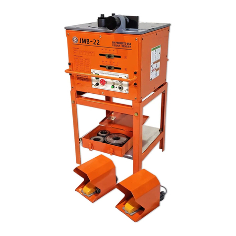
BN Products
BN Products JMB-22 User manual

BN Products
BN Products DIAMOND DBD-20M User manual
BN Products
BN Products SIGMA DSX 25 Installation and operation manual
BN Products
BN Products BNMS-100B User manual
BN Products
BN Products BNHC-20 User manual
BN Products
BN Products DBD Series User manual

BN Products
BN Products DBD-Series User manual

BN Products
BN Products AIRMATIC DBD Series User manual

BN Products
BN Products JMB-22 User manual
