manuals.online logo
Brands
  1. Home
  2. •
  3. Brands
  4. •
  5. BN Thermic
  6. •
  7. Heater
  8. •
  9. BN Thermic OUH3 Series User manual

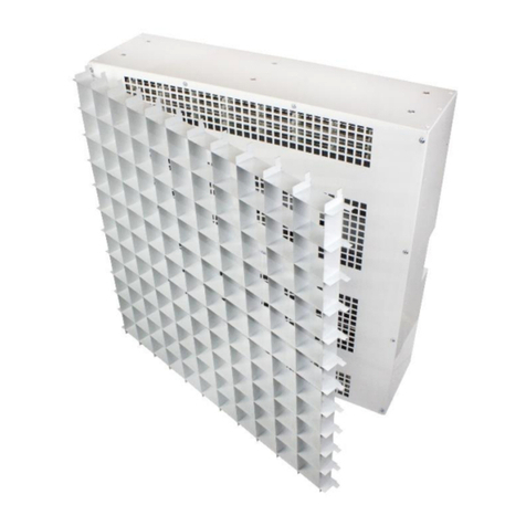
BN Thermic OUH3 Series User manual

This manual suits for next models

6

Other BN Thermic Heater manuals

BN Thermic CH2-15 User manual

BN Thermic

BN Thermic CH2-15 User manual

BN Thermic HCA-09 User manual

BN Thermic

BN Thermic HCA-09 User manual

BN Thermic SystemX XR-30 User manual

BN Thermic

BN Thermic SystemX XR-30 User manual

BN Thermic SystemX XAD-60 User manual

BN Thermic

BN Thermic SystemX XAD-60 User manual

BN Thermic SystemX XC-45 User manual

BN Thermic

BN Thermic SystemX XC-45 User manual

BN Thermic HN3-30L User manual

BN Thermic

BN Thermic HN3-30L User manual

BN Thermic RP3 Series User manual

BN Thermic

BN Thermic RP3 Series User manual

BN Thermic HB-1500 User manual

BN Thermic

BN Thermic HB-1500 User manual

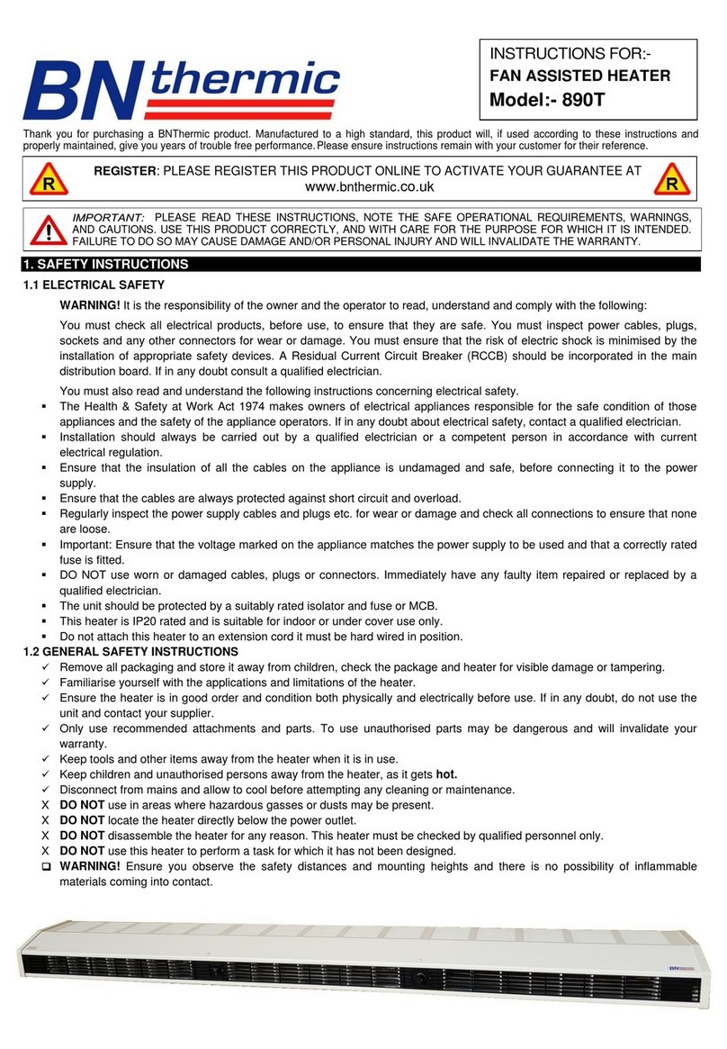
BN Thermic 890T User manual

BN Thermic

BN Thermic 890T User manual

BN Thermic RH-30 User manual

BN Thermic

BN Thermic RH-30 User manual

BN Thermic SMH-45 User manual

BN Thermic

BN Thermic SMH-45 User manual

BN Thermic SMH-60 User manual

BN Thermic

BN Thermic SMH-60 User manual

BN Thermic 800 Series User manual

BN Thermic

BN Thermic 800 Series User manual

BN Thermic SMH-30T User manual

BN Thermic

BN Thermic SMH-30T User manual

BN Thermic CAD-60 User manual

BN Thermic

BN Thermic CAD-60 User manual

BN Thermic CH2-30L User manual

BN Thermic

BN Thermic CH2-30L User manual

BN Thermic SCHG-45 User manual

BN Thermic

BN Thermic SCHG-45 User manual

BN Thermic 860T User manual

BN Thermic

BN Thermic 860T User manual

BN Thermic CHS-30S User manual

BN Thermic

BN Thermic CHS-30S User manual

BN Thermic HN3-45 User manual

BN Thermic

BN Thermic HN3-45 User manual

BN Thermic CH2-30 User manual

BN Thermic

BN Thermic CH2-30 User manual

BN Thermic HN3-15 User manual

BN Thermic

BN Thermic HN3-15 User manual

BN Thermic SMH-30 User manual

BN Thermic

BN Thermic SMH-30 User manual

BN Thermic SCHG-60T User manual

BN Thermic

BN Thermic SCHG-60T User manual

Popular Heater manuals by other brands

Porter-Cable PCXH80KT Operating instructions and owner's manual

Porter-Cable

Porter-Cable PCXH80KT Operating instructions and owner's manual

Dyna-Glo RA18LPDG user manual

Dyna-Glo

Dyna-Glo RA18LPDG user manual

Dimplex PLX050E instruction manual

Dimplex

Dimplex PLX050E instruction manual

EOS Herkules XL S120 installation instructions

EOS

EOS Herkules XL S120 installation instructions

Trebs Comfortheat 99209 manual

Trebs

Trebs Comfortheat 99209 manual

Biddle STYLE2 Series Installation operation & maintenance

Biddle

Biddle STYLE2 Series Installation operation & maintenance

Vermont Castings Non-Catalytic Convection Heater 2477CE Installation and operating manual

Vermont Castings

Vermont Castings Non-Catalytic Convection Heater 2477CE Installation and operating manual

Fagor RA-1505 Instructions for use

Fagor

Fagor RA-1505 Instructions for use

THERMAL FLOW Delta 175 Operating instructions manual

THERMAL FLOW

THERMAL FLOW Delta 175 Operating instructions manual

GET G2CH instructions

GET

GET G2CH instructions

ApenGroup PK Series User, installation, and maintenance manual

ApenGroup

ApenGroup PK Series User, installation, and maintenance manual

oventrop Regucor Series quick start guide

oventrop

oventrop Regucor Series quick start guide

Blaze King CLARITY CL2118.IPI.1 Operation & installation manual

Blaze King

Blaze King CLARITY CL2118.IPI.1 Operation & installation manual

ELMEKO ML 150 Installation and operating manual

ELMEKO

ELMEKO ML 150 Installation and operating manual

KING K Series Installation, operation & maintenance instructions

KING

KING K Series Installation, operation & maintenance instructions

Empire Comfort Systems RH-50-5 Installation instructions and owner's manual

Empire Comfort Systems

Empire Comfort Systems RH-50-5 Installation instructions and owner's manual

Well Straler RC-16B user guide

Well Straler

Well Straler RC-16B user guide

EUROM 333299 instruction manual

EUROM

EUROM 333299 instruction manual

manuals.online logo
manuals.online logoBrands
  • About & Mission
  • Contact us
  • Privacy Policy
  • Terms and Conditions

Copyright 2025 Manuals.Online. All Rights Reserved.

Thank you for purchasing a BN Thermic product. Manufactured to a high standard, this product will, if used according to these
instructions and properly maintained, give you years of trouble-free performance.
To make sure that you have selected the correct heater for your application, please read Section 13 on the back page before
installation.
1. SAFETY INSTRUCTIONS
1.1 ELECTRICAL SAFETY
WARNING! It is the responsibility of the owner and the operator to read, understand and comply with the following:
You must check all electrical products, before use, to ensure that they are safe. You must inspect power cables, sockets and any other
connectors for wear or damage. You must ensure that the risk of electric shock is minimised by the installation of appropriate safety devices.
If in any doubt consult a qualified electrician.
You must also read and understand the following instructions concerning electrical safety.
The Health & Safety at Work Act 1974 makes owners of electrical appliances responsible for the safe condition of those appliances and the
safety of the appliance operators. If in any doubt about electrical safety, contact a qualified electrician.
Installation should in accordance with current IEE electrical regulations.
Ensure that the insulation of all the cables on the appliance are undamaged and safe, before connecting it to the power supply.
Ensure that the cables are always protected against short circuit and overload.
Regularly inspect the power supply cables and plugs etc. for wear or damage and check all connections to ensure that none are loose. This
is especially important on the internal mains connecting terminal block as any vibration may loosen the terminal screws.
Important: Ensure that the voltage marked on the appliance matches the power supply to be used and that a correctly rated fuse is fitted.
DO NOT use worn or damaged cables, plugs or connectors. Immediately have any faulty item repaired or replaced by a qualified electrician.
A suitable local isolating switch must be provided in the electrical supply circuit as close as possible to the heater with at least 3mm clearance
on each pole. This must only be used to turn off the heater in an emergency or once the heater has fully cooled down.
This heater is IP20 rated and is suitable for indoor use only.
The controls and heaters may be fed from a different source, and it is essential that all circuit breakers feeding the heating system are isolated
prior to any work being carried out on any of the heaters in the system.
If there are 2 or more heaters being used as a Master / Slave system there may be 400v ac present in the control boxes due to supplies being
taken from different phases.
If you connect the heaters together in a Master / Slave configuration you can only use one RCD (Residual Circuit Device) for all heaters and
individual MCB’s for each heater.
Do not attach this heater to an extension cord it must be hard wired in position.
1.2 GENERAL SAFETY INSTRUCTIONS
Remove all packaging and store it away from children, check the package and
heater for visible damage or tampering.
Familiarise yourself with the applications and limitations of the heater.
Ensure the heater is in good order and condition both physically and electrically
before use. If in any doubt, do not use the unit and contact your supplier.
Only use recommended attachments and parts. To use unauthorised parts
may be dangerous and will invalidate your warranty.
Keep tools and other items away from the heater when it is in use.
Keep children and unauthorised persons away from the heater, as it gets hot.
Disconnect from mains and allow to cool before attempting any cleaning or
maintenance.
XDO NOT use in areas where hazardous gases or dusts may be present.
XDO NOT locate the heater directly below the power outlet.
XDO NOT disassemble the heater for any reason. This heater must be checked
by qualified personnel only.
XDO NOT use this heater to perform a task for which it has not been designed.

WARNING! Ensure you observe the safety distances and mounting heights
and there is no possibility of inflammable materials coming into contact.
INSTRUCTIONS FOR:-
INDUSTRIAL SPACE HEATER
OUH3 Series
REGISTER: PLEASE REGISTER THIS PRODUCT ONLINE TO ACTIVATE YOUR GUARANTEE AT
www.bnthermic.co.uk
IMPORTANT: PLEASE READ THESE INSTRUCTIONS, NOTE THE SAFE OPERATIONAL REQUIREMENTS, WARNINGS, AND CAUTIONS.
USE THIS PRODUCT CORRECTLY, AND WITH CARE FOR THE PURPOSE FOR WHICH IT IS INTENDED. FAILURE TO DO SO MAY CAUSE
DAMAGE AND/OR PERSONAL INJURY AND WILL INVALIDATE THE WARRANTY.
2. INTRODUCTION & SPECIFICATION
This heater produces a totally dry heat, no condensation, no gas, no fumes. It reaches maximum heat output within a few minutes of
being turned on. It is quick and easy to install reducing installation costs. Air temperature can be controlled by the heater’s built-in
thermostat or alternatively by a variety of remote-mounted thermostats and other control devices. Where required, a group of heaters
can be interconnected and controlled from a single remote-mounted thermostat. This allows a very easy and cheap way of controlling
heating in large or small areas.
3. MOUNTING INSTALLATION
The heater is supplied with a multi-functional mounting bracket.
If required, as an optional extra the heater can be hung using 4 x M8 ring hooks. Order code – OUH3-HK.
LOCATION - For best results, do not mount higher than 2.4m (small models) and 2.8m (large Models). If you need to exceed this
height either mount on the multi-functional bracket so the heater is at an angle facing downwards or use hanging hooks (optional
extra). Direct air flow away from occupants, posts, and columns, including equipment. Ideally allow the warm air to travel parallel to
the outside walls, along the most exposed part of the building, which is normally subjected to the prevailing winds (see pictures below).
MULTI-FUNCTIONAL BRACKET - Using the pictures above and to the right, decide on the best mounting method to suit your
requirements. Fix the bracket to the wall or roof making sure you use suitable bolts for the surface you are fixing the bracket to and
ensure it will take the weight of the heater. Insert the heater’s stud through the bracket, add the washer and secure in place using the
nylock nut supplied.
HANGING EYE HOOKS (Optional extra code – OUH3-HK) – Place the nut onto each eye hook first then fully screw them into the
heater, finally tighten the nuts against the heater body to stop them rotating.
Model
Power
Input Supply
Single
phase
wiring
Amps
Three Phase
wiring
Amps / per
Phase
Dimensions
W x D x H (mm)
Weight
Recommended
Mounting
Height
Safety Distance
from Heater
OUH3-03
3kW
230V ac
13A
----
435 x 405 x 320
18kg
2.4m
2.0m
OUH3-06
6kW
230V ac
26.1A
----
435 x 405 x 320
18kg
2.4m
2.0m
OUH3-09
9kW
230v ac or 400v 3Ph+N
39.2A
13.1A / Ph
435 x 405 x 320
18.5kg
2.4m
2.0m
OUH3-15
15kW
400v 3Ph+N
------
21.75A / Ph
565 x 485 x 445
37kg
2.8m
2.0m
OUH3-20
20kW
400v 3Ph+N
------
29A / Ph
565 x 485 x 445
37.5kg
2.8m
2.0m
OUH3-25
25kW
400v 3Ph+N
------
36.25A / Ph
565 x 485 x 445
38.5kg
2.8m
2.0m
2
Single heater location
Multi heater locations
If you use the heater in mounting position 7, 8 or 9 you MUST
remove the 2 side panels turn them around 180° and reinstall them.
Would you also please turn around the front guard so our Logo
reads correctly. Many Thanks
3
1
3
4
5
6
2
7
8
9
4. ELECTRICAL CONNECTIONS
The 3KW, 6kW can only be wired 230V single phase.
The 9kW can be wired 230V single phase or 400V 3 phase.
The 15kW, 20kW and 25 kW can only be wired 400V 3 phase.
All Heaters MUST BE EARTHED.
Due to the heater having “Fan Over Run” circuitry the heater must not be turned ON and OFF using the mains supply
isolator. The mains supply isolator should only be used in an emergency or if you need to turn off the heater (once cooled
down) for long periods. The heater should be turned off using the thermostat on the back or any approved control device.
See Section 8 for further information on the fan over run.
On 3kW, 6kW and 9kW units there are 4 x 20mm and 1 x 25mm knockouts on the top and bottom of the heater and an additional 4 x 20mm and 1 x
25mm knockouts on the back of the heater. If you require a 32mm hole, gently open out a 25mm hole using a taper drill or step drill. Be careful you
do not touch the internal electrics when opening up the holes.
On 15kW, 20kW and 25kW units there are 3 x 20mm, 1 x 25mm and 1 x 32mm knockouts on the top or bottom of the heater and an additional 3 x
20mm, 1 x 25mm and 1 x 32mm knockouts on the back of the heater.
4.1 OUH3-03 230V Single Phase (only suitable for 3kW model)
Please make sure you have read the Safety instructions and that you are a suitably qualified electrician before continuing.
Please Note:- Specified cable sizes are for typical installations, correction factors may need to be used when determining actual cable sizes.
Do NOT use power tools to undo or do up terminal screws.
Cable Size
Use minimum 1.5mm² 3 Core Mains Cable (see note above).
Connect Brown / Live Wire – Terminal L1 of Heater
Connect Blue / Neutral Wire – Terminal N of Heater
Connect Green/ Yellow / Earth Wire – Terminal E of Heater
PLEASE CHECK ALL CONNECTIONS BEFORE TURNING ON AS
INCORRECT WIRING IS NOT COVERED BY THE GUARANTEE
4.2 OUH3-06 230V Single Phase (only suitable for 6kW model)
Please make sure you have read the Safety instructions and that you are a suitably qualified electrician before continuing.
Please Note:- Specified cable sizes are for typical installations, correction factors may need to be used when determining actual cable sizes.
Do NOT use power tools to undo or do up terminal screws.
The Link Plate should already be present in the terminal block. Do Not remove it.
Cable Size
Use minimum 4mm² 3 Core Mains Cable (see note above).
Connect Brown / Live Wire – Terminal L1 of Heater
Connect Blue / Neutral Wire – Terminal N of Heater
Connect Green/ Yellow / Earth Wire – Terminal E of Heater
PLEASE CHECK ALL CONNECTIONS BEFORE TURNING ON AS
INCORRECT WIRING IS NOT COVERED BY THE GUARANTEE
4
4.3 OUH3-09 230V Single Phase (only suitable for 9kW model)
Please make sure you have read the Safety instructions and that you are a suitably qualified electrician before continuing.
Please Note:- Specified cable sizes are for typical installations, correction factors may need to be used when determining actual cable sizes.
Do NOT use power tools to undo or do up terminal screws.
The 2 Link Plates are attached to these instructions. They link between terminals L1 & L2 + L2 & L3. Please ensure you tighten up the screws
firmly holding them in position.
Cable Size
Use minimum 6mm² 3 Core Mains Cable (see note above).
Connect Brown / Live Wire – Terminal L1 of Heater
Connect Blue / Neutral Wire – Terminal N of Heater
Connect Green/ Yellow / Earth Wire – Terminal E of Heater
PLEASE CHECK ALL CONNECTIONS BEFORE TURNING ON AS
INCORRECT WIRING IS NOT COVERED BY THE GUARANTEE
4.4 400V 3 PHASE – for OUH3-09 (only use when wiring 9kW model 400V 3 phase)
Please make sure you have read the Safety instructions and that you are a suitably qualified electrician before continuing.
Please Note:- Specified cable sizes are for typical installations, correction factors may need to be used when determining actual cable sizes.
Do NOT use power tools to undo or do up terminal screws.
DO NOT USE the Link Plates attached to these instructions.
Cable Size
Use 1.5mm² 5 Core Mains Cable (see note above).
Connect Brown / Phase 1 Wire – Terminal L1 of Heater
Connect Black / Phase 2 Wire – Terminal L2 of Heater
Connect Grey / Phase 3 Wire – Terminal L3 of Heater
Connect Blue / Neutral Wire – Terminal N of Heater
Connect Green/ Yellow / Earth Wire – Terminal E of Heater
PLEASE CHECK ALL CONNECTIONS BEFORE TURNING ON
AS INCORRECT WIRING IS NOT COVERED BY THE
GUARANTEE
4.5 400V 3 PHASE – for OUH3-15, 20 & 25
Please make sure you have read the Safety instructions and that you are a suitably qualified electrician before continuing.
Please Note:- Specified cable sizes are for typical installations, correction factors may need to be used when determining actual cable sizes.
Do NOT use power tools to undo or do up terminal screws.
Cable Sizes
OUH3-15 15kW - Use 4mm² 5 Core Mains Cable (see note above).
OUH3-20 20kW - Use 4mm² 5 Core Mains Cable (see note above).
OUH3-25 25kW - Use 6mm² 5 Core Mains Cable (see note above).
Connect Brown / Phase 1 Wire – Terminal L1 of Heater
Connect Black / Phase 2 Wire – Terminal L2 of Heater
Connect Grey / Phase 3 Wire – Terminal L3 of Heater
Connect Blue / Neutral Wire – Terminal N of Heater
Connect Green/ Yellow / Earth Wire – Terminal E of Heater
PLEASE CHECK ALL CONNECTIONS BEFORE TURNING ON AS INCORRECT
WIRING IS NOT COVERED BY THE GUARANTEE
5
Link
Plates
If you are not using any controls other than the heater’s built-in thermostat AND are not using the heater in a
Master/Slave configuration go to section 7 – LINK CONNECTIONS (page 11).
5. ADDING ADDITIONAL CONTROLS.
You may add the following controls to the OUH3 Space Heater all of these controls if connected as shown in the wiring diagrams
are protected by the heaters internal 3A fuse.
•OUH3-S Heater control switch – Remote way of turning the heater ON/OFF or selecting Fan Only
in the summer. We recommend this as a minimum control for your heater. This can either be wall
mounted or fixed to the back of the heater using knockout and screw holes provided.
•OUH3-DT Digital Thermostat - A 7 Day, 6/1 Day or 5/2 Day programmable thermostat which offers four time and temperature
changes each day. There is also a switch for selecting Fan Only / Off / Heat (if thermostat allows). You may also install a remote
sensor if you wish to install the thermostat in a different location or area to the heaters. All settings are stored in the controller with
battery back-up.
•OUH3-WiFi Wi-Fi version of the OUH3-DT thermostat which can be controlled on a mobile phone. There is also a switch for
selecting Fan Only / Off / Heat (if thermostat allows). You can also use a remote sensor if you wish to allow the thermostat to be
installed in a different location to the heaters. All settings are stored in the controller with battery back-up.
•PROTIM-7 7 Day programmable timer. This timer will only allow the heating to operate during the “ON” time settings. During
“OFF” period there is a “Boost” button that with one press allows heating to operate for 1 hour or with 2 presses 2 hours
before turning off. The boost can be cancelled by pressing the “Boost” button a third time.
•PROSTAT4 The PROSTAT4 thermostat is a highly accurate electronic temperature controller suitable for heavy duty use
in public areas. There are two temperature settings switchable through a push button and integral countdown timer. Optional
remote sensors are available if temperature control is required away from the controller.
•RST-RS Rough service, tamper resistant thermostat – Can be used on its own as a room thermostat or in conjunction with the
OUH3-S Heater control switch.
•FST-RS Rough Service, tamper resistant frost thermostat –This thermostat overrides all other controls including the OUH3-S,
OUH3-DT or OUH3-Wi=IFI when they are set to OFF. This is used to protect the heated area against low temperatures that
may cause damage or freezing of water etc. The thermostat MUST be mounted out of direct air flow of the heater.
•PROSTAT2 Battery Operated Digital Thermostat is a 7 Day or 5/2 Day programmable room thermostat which offers six time
and temperature changes each day. All settings are stored in the controller.
•RST3-IN thermostat – Can be used on its own as a room thermostat or in conjunction with the OUH3-S Heater control switch.
•CXS Remote Temperature Sensor – Used with OUH3-DT and OUH3-WiFi to read temperature in a different area to the controller.
If you connect heaters in a Master / Slave configuration (See Section 6) controls are only added to the master heater and all
the slave heater(s) will follow the master.
OUH3-S
Heater Control Switch
RST-RS / FST-RS
Tamper Resistant thermostats
PROTIM-7
7 Day Time Switch
RST3-IN
Thermostat
6
PROSTAT4
2 Set Point Thermostat
PROSTAT2
Battery Digital Thermostat
OUH3-DT
Digital Thermostat
+ Fan Only
Switch
OUH3-WiFi
WiFi Thermostat + Fan Only Switch
CXS
Remote Sensor
5.1 CONECTING A OUH3- S HEATER CONTROL SWITCH
This can either be mounted on a wall or on the back of the heater next to the thermostat. If mounting on the heater, remove the knockout in the heater
and electrical box of the OUH3-S and screw onto the heater using 2 x M4 screws and nuts (not supplied).
Use 0.75mm² 4 core cable
Connections – (Colours for reference only)
Connect Brown Live wire – Terminal 3 of Heater and Terminal L on Control Switch (230V Live connection).
Connect Grey Live wire – Terminal 4 of Heater and Terminal 1 on Control Switch.
Connect Black wire – Terminal 5 of Heater and Terminal 2 on Control Switch.
Connect Green / Yellow wire – Terminal E or of Heater and Terminal E (Earth connection) on Control Switch.
PLEASE CHECK ALL CONNECTIONS BEFORE TURNING ON AS INCORRECT WIRING IS NOT COVERED BY THE GUARANTEE
5.2 CONECTING A RST-RS or RST3 -IN THERMOSTAT & OUH3 - S CONTROL SWITCH
HEATER to CONTROL SWITCH
Use 0.75mm² 3 or 4 core cable
Connections – (Colours for reference only)
Connect Brown Live wire – Terminal 3 of Heater and Terminal L on Control Switch (230V Live connection).
Connect Grey Live wire – Terminal 4 of Heater and Terminal 1 on Control Switch.
Connect Green / Yellow wire – Terminal E or of Heater and Terminal E (Earth connection) on Control Switch.
HEATER to THERMOSTAT
Use 0.75mm² single core wire OR add it to multi core cables
Connect Black wire – Terminal 5 of Heater and Terminal Lout on RST-RS Thermostat or Terminal 3 on RST3-IN Thermostat. Please note; Black wire
can be joined in the control switch using a suitable terminal block to allow easy install of controls. Black wire carries 230v.when thermostat is on.
CONTROL SWITCH to THERMOSTAT
Use 0.75mm² 2 or 3 core cable
Connections – (Colours for reference only)
Connect Red wire – Terminal 2 of Control Switch and Terminal Lin on RST-RS Thermostat or Terminal 1 on RST3-IN Thermostat.
Connect Green / Yellow wire – Terminal E or of Control Switch and Terminal E (Earth connection) on Thermostat.
PLEASE CHECK ALL CONNECTIONS BEFORE TURNING ON AS INCORRECT WIRING IS NOT COVERED BY THE GUARANTEE
PLEASE NOTE:-Turn up fully the internal thermostat on the back of the heater so it does not override this thermostat.
The controls and heaters may be fed from a different source and it is essential that
all circuit breakers feeding the heating system are isolated prior to any work being
carried out on any of the heaters in the system.
OUH3-S Mounted on the
back of the heater
Links may be
required
– S
ee
Section 7
Links may be
required
– S
ee
Section 7
The controls and heaters may be fed from a different
source and it is essential that all circuit breakers feeding
the heating system are isolated prior to any work being
carried out on any of the heaters in the system.
7
5.3CONECTING A OUH3-DT OR A OUH3-WiFi THERMOSTAT + FAN ONLY OPTION
PLEASE CHECK ALL CONNECTIONS BEFORE TURNING ON AS INCORRECT WIRING IS NOT COVERED BY THE GUARANTEE
5.4CONECTING A FST- RS FROST PROTECTION THERMOSTAT
5.5CONECTING A PROTIM-7 7 DAY PROGRAMABLE TIMER
Use 0.75mm² 4 core cable
Connections – (Colours for reference only)
Connect Brown Live wire – Terminal 1 of Heater and Terminal L on
Programmable Timer (230V Live connection).
Add a Link cable (1mm²) between Timer L connection and Timer Sin
connection.
Connect Black wire – Terminal 2 of Heater and Terminal Sout on
Programmable Timer.
Connect Blue Neutral wire – Terminal N of Heater and Terminal N on Programmable Timer (230V Neutral connection).
Connect Green / Yellow wire – Terminal E or of Heater and Terminal E (Earth connection) on Programmable Timer.
PLEASE CHECK ALL CONNECTIONS BEFORE TURNING ON AS INCORRECT WIRING IS NOT COVERED BY THE GUARANTEE
8
The controls and heaters may be fed from a different source and it is essential that all circuit breakers feeding the heating system are isolated prior
to any work being carried out on any of the heaters in the system.
Use
0.75mm² 5 core cable
Connections
– (Colours for reference only)
Connect Brown Live wire
– Terminal 1 of Heater and Terminal “Lin” on Control Switch.
Connect Grey Live wire
– Terminal 4 of Heater and Terminal “Fan” on Control Switch.
Connect Black wire
– Terminal 5 of Heater and Terminal “Heat” on Control Switch.
Connect Bl
ue wire – Terminal N of Heater and Terminal N on Control Switch.
Connect Green / Yellow wire
– Terminal E or of Heater and Terminal E on Control
Switch
Links may be
required
– S
ee
Section 7
The controls and heaters may be fed from a different source and it is essential that all circuit breakers feeding the heating system are isolated
prior to any work being carried out on any of the heaters in the system.
Use 1.0mm² 3 core cable
Connections
– (Colours for reference only)
Connect Black wire
– Terminal 10 of Heater and Lout on Frost Thermostat.
Connect Brown Live wire
– Terminal 11 of Heater and Lin on Frost Thermostat (230V Live
connection).
Connect Green / Yellow wire
– Terminal E or of the Heater
PLEASE CHECK ALL CONNECTIONS BEFORE TURNING ON AS INCORRECT WIRING
IS NOT COVERED BY THE GUARANTEE
.
Links may be required
– See Section 7
The controls and heaters may be fed from a different source and it is essential that all circuit breakers feeding the heating system are isolated
prior to any work being carried out on any of the heaters in the system.
NO additional
Links are required.
5.6 CONECTING A RST3- IN or RST-RS THERMOSTAT
Use 1.0mm² 3 core cable
Connections – (Colours for reference only)
Connect Red wire – Terminal 3 of Heater and Terminal 1 on an RST3-IN Thermostat or Terminal Lin on an RST-RS Thermostat.
Connect Black wire – Terminal 5 of Heater and Terminal 3 on an RST3-IN Thermostat or Terminal Lout on an RST-RS Thermostat.
Connect Green / Yellow wire – Terminal E or of Heater and Terminal E (Earth connection) on either Thermostat.
PLEASE CHECK ALL CONNECTIONS BEFORE TURNING ON AS INCORRECT WIRING IS NOT COVERED BY THE GUARANTEE
PLEASE NOTE:-Turn up fully the internal thermostat on the back of the heater so it does not override this thermostat
5.7 CONECTING A PROSTAT4 THERMOSTAT
Use 0,75mm² 4 core cable
Connections – (Colours for reference only)
Connect Red wire – Terminal 3 of Heater and Power IN - Live Terminal (L) on Thermostat.
Connect Black wire – Terminal 5 of Heater and Heaters Live Terminal (L) on Thermostat. Black wire carries 230v when thermostat is on.
Connect Blue Neutral wire – Terminal N of Heater and Power IN - Neutral Terminal (N) on Thermostat.
Connect Green / Yellow wire – Terminal E or of Heater and Terminal E (Earth connection) on Thermostat.
PLEASE CHECK ALL CONNECTIONS BEFORE TURNING ON AS INCORRECT WIRING IS NOT COVERED BY THE GUARANTEE
PLEASE NOTE:-Turn up fully the internal thermostat on the back of the heater so it does not override this thermostat
5.8CONECTING A PROSTAT2 THERMOSTAT
Use 1.0mm² 3 core cable
Connections – (Colours for reference only)
Connect Brown Live wire – Terminal 1 of Heater and Terminal 2 on the Thermostat (230V
Live connection).
Connect Grey Live wire – Terminal 2 of Heater and Terminal 3 on the Thermostat.
PLEASE CHECK ALL CONNECTIONS BEFORE TURNING ON AS INCORRECT WIRING IS NOT COVERED BY THE GUARANTEE
PLEASE NOTE:-Turn up fully the internal thermostat on the back of the heater so it does not override this thermostat.
The controls and heaters may be fed from a different source and it is
essential that all circuit breakers feeding the heating system are isolated
prior to any work being carried out on any of the heaters in the system.
Links may be
required
– S
ee
Section 7
The controls and heaters may be fed from a different source and it is
essential that all circuit breakers feeding the heating system are isolated
prior to any work being carried out on any of the heaters in the system.
Links may be
required
– S
ee
Section 7
9
Links may be
required
– S
ee
Section 7
6. CONECTING HEATERS IN A MASTER SLAVE ARANGEMENT
IF USING THE HEATERS IN A MASTER / SLAVE ARANGEMENT PLEASE READ THE FOLLOWING IMPORTANT NOTES
BEFORE STARTING THE INSTALATION.
All OUH3 heaters may be connected in a Master / Slave arrangement.
The OUH3 heaters do not need to be the same Wattage or size.
Some OUH3 can be connected using 400v 3 phase supply and some Single phase and still linked as Master / Slaves.
If Using RCD (Residual Circuit Device) all Heaters connected in a Master / Slave arrangement MUST be supplied from the same
RCD and not multiple RCD’s. Then use a MCB for each heater.
The controls are always added to the master heater and NEVER to any of the slave heaters. You may designate any OUH3 heater
to be the master as long as you adhere to the following.
1) Controls are only added to the master unit.
2) Controls if connected as shown in the wiring diagrams on pages 7 – 9 are protected by the master heaters internal 3A fuse.
3) Link connections / cables (see section 7), if required are only added to the master unit.
4) You are fully aware that if a slave unit is present in the system 400v ac may be present in the terminal blocks even if all heaters
are run on single phase. This is because the supply to each heater may be taken from a different phase.
5) A maximum of 1 master and 15 slaves are used in each configuration.
6) Older OUH2 model heaters can still be connected to these new OUH3 models.
Connect the mains wire to each heater as per section 4.
Decide which heater is going to be the master heater and connect the controls to it as per section 5.
Link the master to the first slave as per drawing below and instructions on next page.
Link first slave to second slave as per drawing below and instructions on next page.
Linking Heater in a Master / Slave Configuration
The controls and heaters may be fed from
a different source and it is essential that
all circuit breakers feeding the heating
system are isolated prior to any work
being carried out on any of the heaters in
the system.
10