Bo-Lang FIT-AOXIN-E8-AB2E User manual

- 1 -
HOME GYM MULTI
STATION USER MANUAL
SKU: FIT-AOXIN-E8-AB2E

- 2 -
CONTENTS
Contents ........................................................................................................2
Safety Instruction .......................................................................................3
Product Overview .......................................................................................4
Parts List ........................ .... ...........................................................................5-9
Assembly Instruction .................................................................................9-22
Daily Care & Maintenance .......................................................................22
• Product may vary slightly from item pictured due to model upgrades.
• Please check the packing details before assembly, if there is any missing part, contact after-
sales service department for support.
•
Please read all instructions carefully before using the product. Retain this user manual for future
reference.

- 3 -
Safety Instruction
IMPORTANT SAFETY INSTRUCTIONS
WARNING: To reduce the risk of serious injury, read all important precautions and
instructions in this manual and all warnings on your machine before using your
machine. We assume no responsibility for personal injury or property damage
sustained by or through the use of this product.
1. Please read, understand manual and all warnings, test the usage before using
the machine. It is the responsibility of the owner to ensure that all users of
this machine are adequately informed of all warnings and precautions.
2. Retain this user manual for current and future reference, and make sure all
warning labels are clear and complete.
3. This machine is recommended to be installed by at least two adults.
4. Before beginning this or any exercise program, consult your physician. This is
especially important for persons over age 35 or persons with pre-existing
health problems.
5. Keep children and pets away and safe from the machine at all times.
6. Pulleys and cables should be checked for wear frequently and replaced as
needed, so as to avoid any danger to you or the people around.
7. Wear appropriate exercise clothes while using the machine.
8. Inspect and properly tighten all parts of the machine regularly, especially
ropes to avoid any injury. If something thing is wrong, stop using and contact
our after-sales service department for support.
Required Tools: Spanner and Allen Wrench

- 4 -
Product Overview
E8
Executive Standard:
GB17498.1

- 5 -
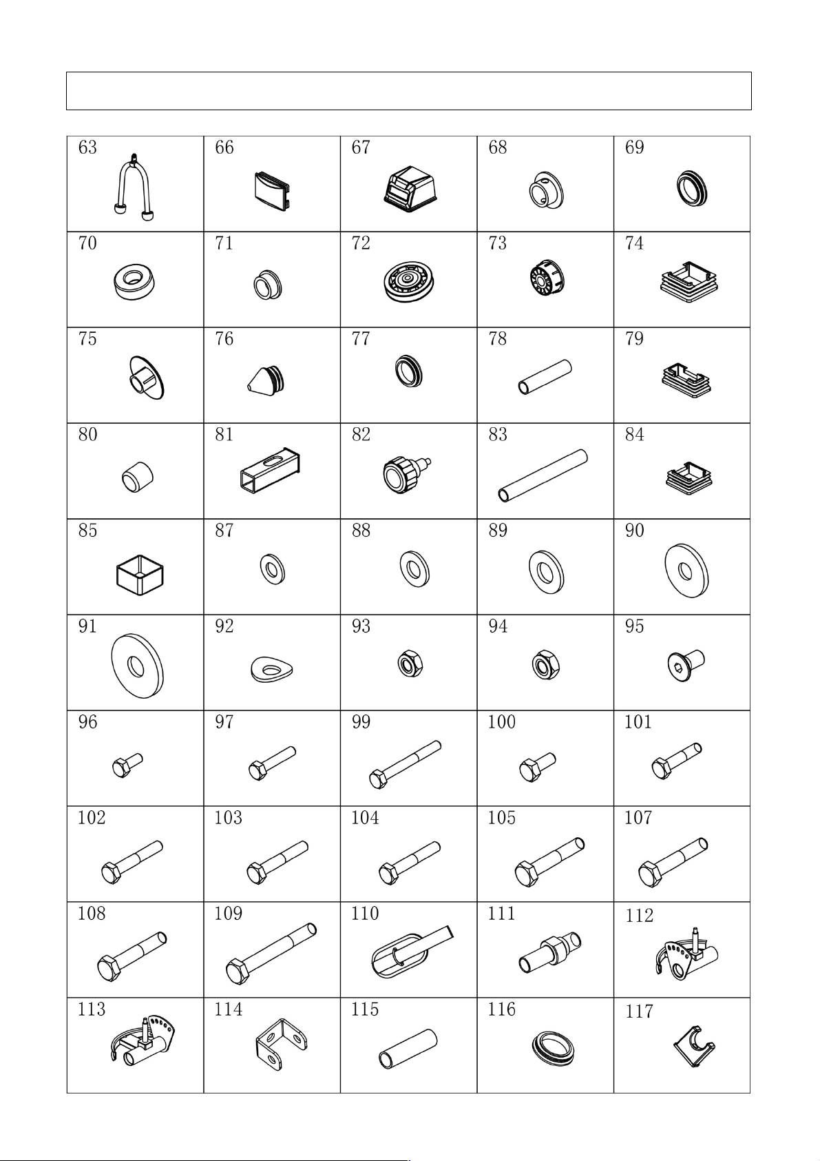
Parts List
No.
Part
Quantity
No.
Part
Quantity
1
Front Base Frame
1
28
Double Pulley U-clamp
Bracket
1
2
Front Vertical Frame
1
30
Lat Bar
1
3
Main Base Frame
1
31
Adjustable Joint Plate
2
4
Guide Rod
2
32
Low Row Bar
1
5
Rear Base Frame
1
33
Left Weight Stack Shroud
1
6
Left Butterfly Rotatable
Extended Arm
1
34
Right Weight Stack Shroud
1
7
Right Butterfly Rotatable
Extended Arm
1
44
Stabilizer Latch
1
8
Side Bottom Frame
2
45
L-shaped Weight Locking
Pin
1
9
Foot Plate
1
46
Pivot Axle (for #16)
1
10
Low Row Round Tube
1
47
Hoist Hook
5
11
Selector Rod
1
48
Chain (280mml)
2
12
Front Top Main Frame
1
49
Φ17 Powdered Metal
Busing
6
13
Rear Top Main Frame
1
51
Back Pad
1
14
Top Connecting Plate
1
52
Seat Pad
1
15
Weld Plate (for #2)
1
53
Armrest Pad
1
16
Butterfly Connector
1
56
Φ53xΦ90x245L
Foam Roller
2
17
Pulley U-clamp Bracket
2
57
Φ25xΦ80x160L
Foam Roller
4
18
Left Butterfly Arm Set
1
58
Butterfly Cable (2890mml)
1
19
Right Butterfly Arm Set
1
59
Lat Pulldown Cable
(3220mml)
1
20
Hand Grip
2
60
Low Row Cable (3850mml)
1
21
Leg Extension Connector
1
61
Weight Plate Top Cover
1
22
Leg Extension Frame
1
62
Weight Plate
12
23
Leg Extension Arm
1
63
Ab Strap
1
24
Seat Pad Weld Plate
1
66
50x75 Tube Plug
6
25
Seat Pad T-shaped Frame
1
67
50x75 Foot Cap
5
26
Armrest Pad Frame
1
68
Stabilizer Bushing
1
27
Φ25 Foam Roller Tube
(440mml)
2
69
Φ32 Tube Plug
2

- 6 -
Parts List
No.
Part
Quantity
No.
Part
Quantity
70
Weight Plate Cushion
2
101
M10x45 Hex bolt
14
71
Φ19 Powdered Metal
Busing
6
102
M10x60 Hex bolt
2
72
Pulley
18
103
M10x65 Hex bolt
3
73
(Leg Extension) Frame
Bushing
2
104
M10x70 Hex bolt
5
74
50x50 Tube Plug
2
105
M10x80 Hex bolt
1
75
Φ25 Foam Cap
4
107
M10x95 Hex bolt
6
76
Selector Rod Plug
1
108
M10x100 Hex bolt
4
77
Φ25 Tube Plug
6
109
M10x175 Hex bolt
1
78
Φ25 Low Row Foam
4
110
Foot Strap
1
79
25x50 Tube Plug
5
111
Butterfly Extension Fix
Shaft
2
80
Φ25 Tube Sleeve
2
112
Left Butterfly Adjustable
Component
1
81
50x50 Lock Tube
2
113
Right Butterfly Adjustable
Component
1
82
Tightening Knob
2
114
U-shaped Bracket
2
83
Φ25 Lat Pulldown Foam
2
115
Φ28 Butterfly Foam
2
84
38x38 Square Tube Plug
4
116
Φ28 Tube Plug
2
85
38x38 Square Tube Sleeve
2
117
Plastic Buckle
2
87
Φ8Washer
16
118
Φ60 Tube Plug
4
88
Φ10 Washer
76
119
Pop pin (Round)
2
89
Φ12 Washer
2
120
Nylon Bushing
4
90
Φ10 Big Washer
2
121
M24*1.5 Screw Cap
2
91
Φ12 Big Washer
1
122
Ø26 Big Washer
4
92
Φ10 Arc Washer
2
123
Ø26 Wavy Washer
2
93
M10 Nut
36
124
ST4.2×25 Screw
2
94
M12 Nut
2
95
M10x20 Socket Hex Bolt
2
96
M8x16 Hex bolt
12
97
M8x40 Hex bolt
2
99
M8x95 Hex bolt
2
100
M10x25 Hex bolt
6

- 7 -
Parts List
- 8 -
Parts List

- 9 -
Parts List
Assembly Instruction
Attention:
1. Put the washers to the two ends of bolts.
2. Finger tighten all bolts and nuts, do not spanner tighten firmly until this machine is
fully assembled.
3. Some components have been well pre-assembled in cartons.
4. This machine is recommended to be installed by at least two adults.
- 10 -
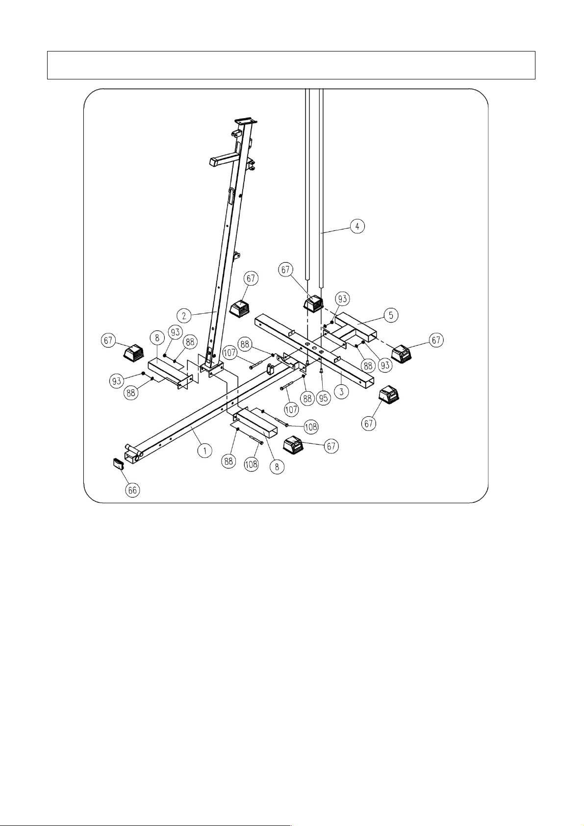
Assembly Instruction
Picture 1:
1. Attach a “50x75 Tube Plug” (#66) to Front Base Frame (#1); Attach six “50x75 Foot Cap”
(#67) to Side Bottom Frame (#8), Main Base Frame (#3) and Rear Base Frame (#5).
2. The three holes on Main Base Frame (#3) should face upward, then be inserted by two
Guide Rod (#4), tighten them firmly by using two M10x20 Socket Hex Bolt (#95).
3. Attach Front Base Frame (#1), Main Base Frame (#3) and the Rear Base Frame (#5) firmly
by using:
• M10x95 Hex bolt (#107) x 2
• Φ10 Washer (#88) x 4
• M10 Nut (#93) x 2
4. Put Front Vertical Frame (#2) on Front Base Frame (#1), then attach both of Side Bottom
Frame (#8) and Front Vertical Frame (#2) to Front Base Frame (#1) by using:
• M10x100 Hex bolt (#108) x 2
• Φ10 Washer (#88) x 4
• M10 Nut (#93) x 2

- 11 -
Assembly Instruction
Picture 2:
1. Slide two Weight Plate Cushions (#70) through two Guide Rods (#4) respectively, followed
by 12 Weight Plate (#62). Make sure the holes on weight plates are facing down as shown;
2. Slide Stabilizer Bushing (#68) through Selector Rod (#11) with their holes aligned well, and
insert Stabilizer Latch (#44) into the holes.
3. Then slide the Selector Rod (#11) into the top-middle hole of Weight Plate (#62), make sure
the rod holes (#11) and weight plate holes (#62) are facing the same direction.
4. Slide Weight Plate Top Cover (#61) through the Guide Rods (#4) and Selector Rod (#11).
Place Φ12 Big Washer (#91) on top of Weight Plate Top Cover (#61).
5. Attach Foot Plate (#9) to the Front Base Frame (#1) by using Low Row Round Tube (#10),
end with two Φ30 Hole Plugs (#69) at two sides respectively.

- 12 -
Assembly Instruction
Picture 3:
1. Attach three “50x75 Tube Plug” (#66) to Front Top Main Frame (#12) and Top Connecting
Plate (#13) as shown.
2. Put Rear Top Main Frame (#13) on Guide Rod (#4) with its big holes facing down by using:
• M10x25 Hex bolt (#100) x 2
• Φ10 Washer (#88) x 2
3. Attach Front Top Main Frame (#12) to Front Vertical Frame (#2) by using:
• M10x70 Hex bolt (#104) x 2
• Φ10 Washer (#88) x 4
• M10 Nut (#93) x 2
• Top Connecting Plate (#14) x 1
4. Then fix the Front Top Main Frame (#12) to Front Vertical Frame (#2) firmly by using:
• M10x95 Hex bolt (#107) x 2
• Φ10 Washer (#88) x 4
• M10 Nut (#93) x 2
• Weld Plate (#15) x 1
- 13 -
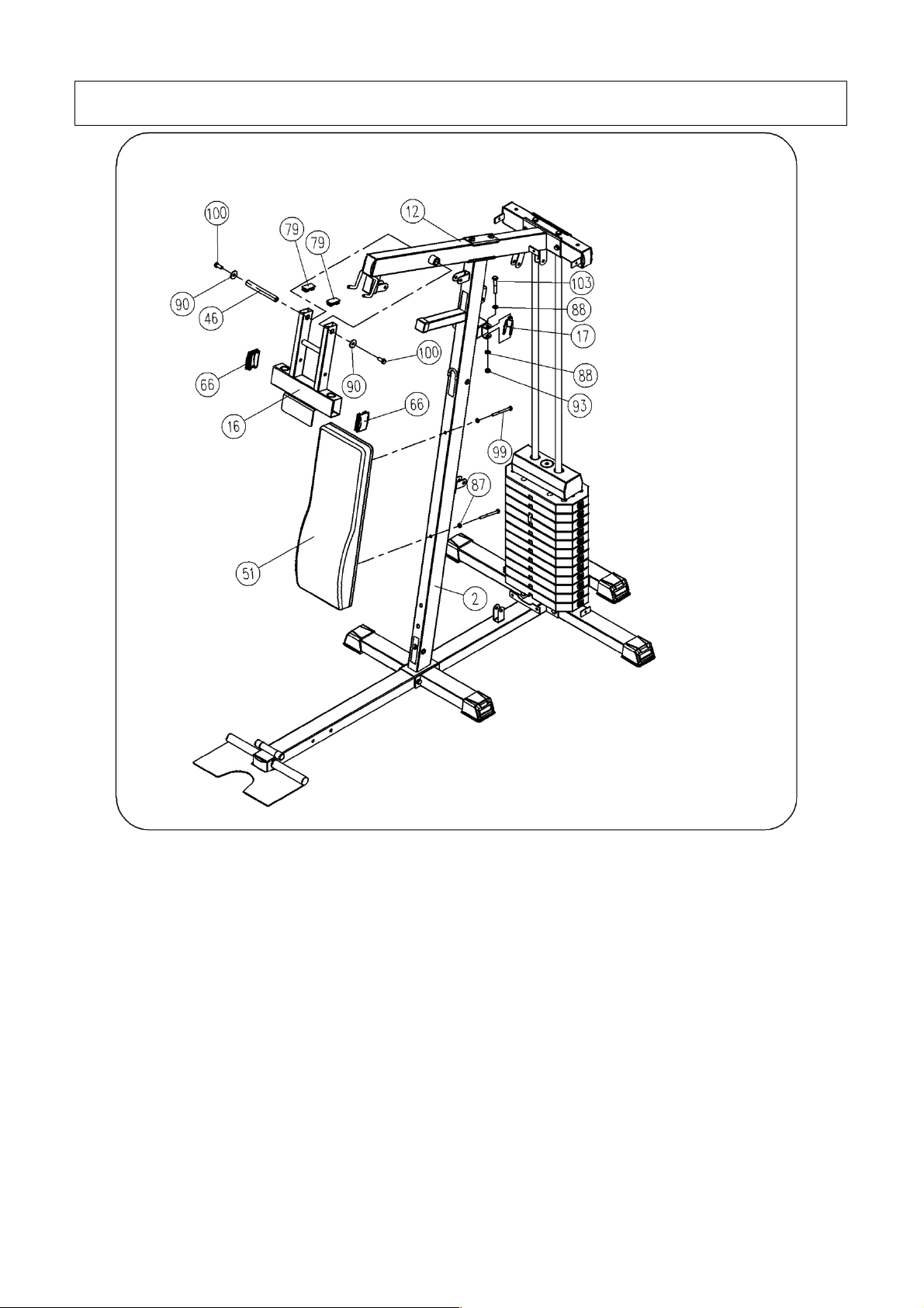
Assembly Instruction
Picture 4:
1. Fix two Pulley U-clamp Brackets (#17) onto the U-shaped brackets of Front Vertical Frame
(#2) by using:
• M10x65 Hex bolt (#103) x 2
• Φ10 Washer (#88) x 4
• M10 Nut (#93) x 2
2. Place the following plugs on Butterfly Connector (#16) as shown.
• 25x50 Tube Plug (#79) x 2
• 50x75 Tube Plug (#66) x 2
3. Attach the Butterfly Connector (#16) to Front Top Main Frame (#12) by inserting Pivot Axle
(#46). When the lengths of two ends (#46) are equal, fix it (#46) by using:
• M10x25 Hex bolt (#100) x 2
• Φ10 Big Washer (#90) x 2
4. Attach Back Pad (#51) to Front Vertical Frame (#2) by using:
• M8x95 Hex bolt (#99) x 2
• Φ8 Washer (#87) x 2

- 14 -
Assembly Instruction
Picture 5:
1. Slide Φ53xΦ90x245L foam roller (#56) through Left Butterfly Arm Set (#18).
2. Attach all of Left Butterfly Rotatable Extended Arm (#6), U-shaped Bracket (#114) and Hand
Grip (#20) to the Left Butterfly Arm Set (#18) by using:
• M10x60 Hex bolt (#102) x 1
• Φ10 Washer (#88) x 2
• Φ10 Arc Washer (#92) x 1
3. Fix the Left Butterfly Adjustable Component (#112) to Butterfly Connector (#16) firmly by
using:
• Φ12 Washer (#89) x 1
• M12 Nut (#94) x 1
4. Put two nylon bushings (#120) at two ends of Left Butterfly Adjustable Component (#112).
Then slide a Ø26 wavy washer (#123) and a Ø26 big washer (#122) in turn onto the top
shaft of Left Butterfly Arm Set (#18). After that fix them firmly by using:
• Φ26 Big washer (#122) x 1
• M24*1.5 Screw Cap (#121) x 1
5. Please repeat the same steps for the right side.
- 15 -
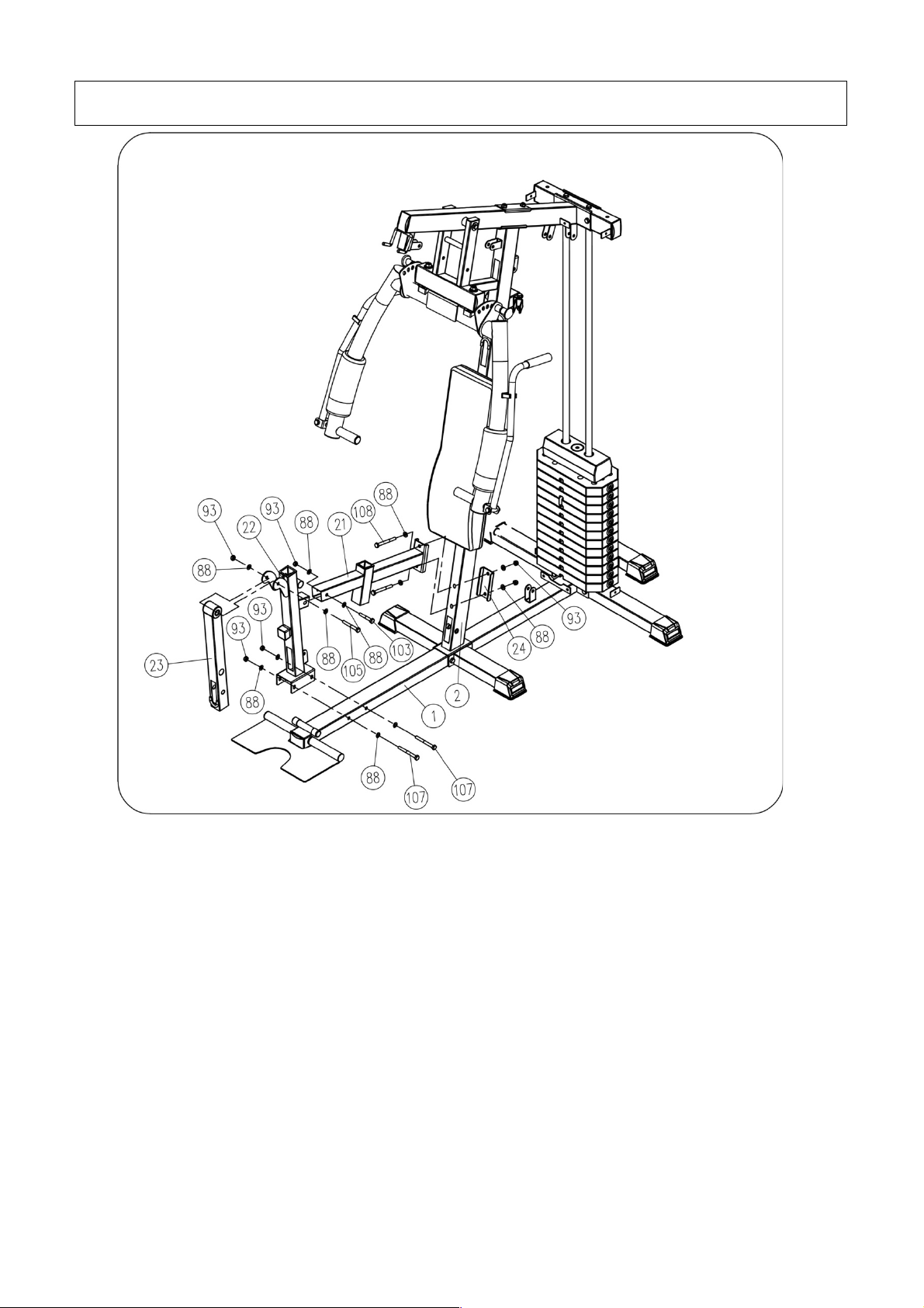
Assembly Instruction
Picture 6:
1. Attach Leg Extension Frame (#22) to Leg Extension Connector (#21) by using:
• M10x65 Hex bolt (#103) x 1
• Φ10 Washer (#88) x 2
• M10 Nut (#93) x 1
2. Attach Leg Extension Connector (#21) to Front Vertical Frame (#2) by using:
• M10x100 Hex bolt (#108) x 2
• Φ10 Washer (#88) x 4
• M10 Nut (#93) x 1
• Seat Pad Weld Plate (#24) x 1
3. Attach Leg Extension Frame (#22) to Front Base Frame (#1) by using:
• M10x95 Hex bolt (#107) x 2
• Φ10 Washer (#88) x 4
• M10 Nut (#93) x 1
4. Attach Leg Extension Arm (#23) to Leg Extension Frame (#22) by using:
• M10x80 Hex bolt (#103) x 1
• Φ10 Washer (#88) x 2
• M10 Nut (#93) x 1

- 16 -
Assembly Instruction
Picture 7:
1. Attach Seat Pad (#52) to T-shaped Frame (#25) by using:
• M8x40 Hex bolt (#97) x 2
• Φ8 Washer (#87) x 2
2. Attach Armrest Pad (#53) to Armrest Pad Frame (#26) by using:
• M8x16 Hex bolt (#97) x 4
• Φ8 Washer (#87) x 4
3. Insert the Seat Pad T-shaped Frame (#25) just assembled into Leg Extension Connector
(#21) with a tightening knob (#82) screwed on.
4. Insert the Armrest Pad Frame (#26) (#25) just assembled into Leg Extension Frame (#22)
with a tightening knob (#82) screwed on.

- 17 -
Assembly Instruction
Picture 8:
1. Slide two Φ25 Foam Roller Tube (440mml) (#27) into Leg Extension Arm (#23) and Leg
Extension Frame (#22) respectively.
2. Slide two Φ25xΦ80x160L foam rollers (#57) onto two ends of the Roller Tube (#27).
3. Plug two Φ25 foam caps (#74) at the two ends of Roller Tube (#27).

- 18 -
Assembly Instruction
Butterfly Cable
Picture 9:
1. Fix one end of Butterfly Cable (2890mml) (#58) to Right Butterfly Adjustable Component (#113)
by using:
• M10x25 Hex bolt (#100) x 1
• Φ10 Washer (#88) x 2
• M10 Nut (#93) x 1
2. For the other end of Butterfly Cable (2890mml) (#58), route the cable around the pulleys (#72) as
fixed as shown. Then fix the cable end to Left Butterfly Adjustable Component (#112).

- 19 -
Assembly Instruction
Lat Pulldown Cable
Picture 10:
1. Fix one end of Lat Pulldown Cable (3220mml) (#59), route the cable around the pulleys (#72)
as fixed as shown, then ends at tightening it with Selector Rod (#11).
2. Connect the Lat Bar (#30) and the head ball of Lat Pulldown Cable (#59) (3220mml)
together by two hoist hooks (#47) and the chain (280mml) (#48).

- 20 -
Assembly Instruction
Low Row Cable
Picture 11:
1. Find the Low Row Cable (3850mml) (#60), remove one of its ball heads, then route the cable
around the pulleys (#72) as fixed as shown, end with re-installing the ball head which was
removed at the beginning. Finally connect it with hoist hook (#47) and Ab strap (#63).
2. Connect the Low Row Bar (#32) to the end of this cable (#60) by using two hoist hooks (#47)
and a chain (280mml) (#48).
Friendly Reminder:
Please check whether the cable is tight enough or not. If it is slightly loose, it
could be adjusted by changing the screw-in length at the end head of Lat Pulldown Cable (#59). If it
is very loose, it could also be adjusted by changing the hole on the Adjustable Joint Plate (#31)
where pulley (#72) is fixed.
Table of contents
Other Bo-Lang Home Gym manuals

Popular Home Gym manuals by other brands


Body Craft
Body Craft STRATA instruction manual

Life Fitness
Life Fitness SU55 Assembly & parts list

Life Fitness
Life Fitness ROW CX owner's manual

Life Fitness
Life Fitness Smith Machine PL06 Assembly instructions

Life Fitness
Life Fitness SU45 Assembly & parts list

Life Fitness
Life Fitness SBWBE owner's manual