Bobe CMP User manual

IMPORTANT SAFETY INFORMATION: READ AND FOLLOW ALL INSTRUCTIONS
Save these instructions. Leave manual with homeowner after installation.
Improper installation, adjustment, alteration, service, or lack of maintenance can cause injury or property damage. Read
the installation, operating, & maintenance instructions thoroughly before installing or servicing this equipment.
FIRE FEATURE “DIY” KITS
INSTALLATION INSTRUCTIONS - AUTO IGNITION
SAVE THESE INSTRUCTIONS FOR FUTURE REFERENCE
®
Scan for Step by Step instructions, or visit
www.c-m-p.com/tech

2 3
WARNING Do not store or use gasoline or ammable vapors and liquids in vicinity of this appliance.
Do not install this appliance near any combustibles. A Liquid Propane cylinder not connected for
use shall not be stored in the vicinity of this or any other appliance.
WARNING For outdoor use only. Product is not intended to be a starter for wood or any other combustibles.
WARNING Installation must be performed by a licensed professional. Improper installation, adjustment,
alteration, service or maintenance can cause injury or property damage. Installer must follow all
local codes as well as National Fuel Gas Code, ANSI Z223.1.
CAUTION If you smell gas, shut o the gas to the appliance and extinguish any open ame. If the odor lingers
keep away from appliance and immediately call gas supplier or re department. Do not leave any
ame unsupervised.
DANGER
Carbon Monoxide Hazard: This appliance can produce carbon monoxide which has no odor. Using
it in an enclosed space can cause serious injury or death. Never use this appliance in an enclosed
space such as a camper, tent, car or home.
CAUTION
HOT! DO NOT TOUCH. SEVERE BURNS MAY RESULT. CLOTHING IGNITION MAY RESULT.
Glass and other surfaces are hot during operation and cool-down. CAREFULLY SUPERVISE children
near this appliance. Alert children and adults to hazards of high temperatures.
SAVE THESE INSTRUCTIONS
ADHERE TO ALL LOCAL CODES CONCERNING INSTALLATION AND
OPERATION.
• Test for gas leaks prior to use.
• Verify correct gas fuel type. Never use an alternative fuel, including bio-fuel, ethanol, lighter uid or any other fuel.
• Installation must be performed by licensed gas piping professional
• When pit is not in use for an extended period, turn o gas to prevent unwanted start-up.
• The use of a cover when not in operation is recommended
• Verify gas shut o is located outside of the re enclosure. The gas shuto should NOT be used to adjust ame height.
• An approved gas valve or keyed valve shall be installed upstream of the unit and located in an accessible area that is
within 5ft from the unit.
NOTICE
It is CRITICAL that all LP units are checked for back pressure after media has been installed.
WARNING
Do not modify units from factory conguration. Doing so will void the warranty.
NOTICE
Manufacturer is not responsible for damage due to improper installation.
IMPORTANT WARNINGS & SAFETY INSTRUCTIONS
READ AND FOLLOW ALL INSTRUCTIONS B. SYSTEM REQUIREMENTS
Installation must be performed by a licensed contractor. Installer must follow all local codes as well as National Fuel Gas
Code, ANSI Z223.1. We suggest that our products be serviced annually by a professional certied in the US by the National
Fireplace Institute (NFI) as NFI Gas Specialists or in Canada by WETT (Wood Energy Technical Training). Installer must follow all
instructions carefully to ensure proper performance and safety.
NOTICE
This Product is for outdoor use only.
WARNING
Do not modify units from factory conguration. Doing so will void the warranty.
GAS REQUIREMENTS
RECOMMENDED GAS PRESSURE
DESCRIPTION WATER COLUMN
LIQUID PROPANE 8.5 - 11”WC
NATURAL GAS 3.5 - 7” WC
NOTE: CHECK WITH YOUR GAS SUPPLIER TO VERIFY GAS FLOWS AND PRESSURES AVAILABLE
AT THE LOCATION OF YOUR INSTALLATION. IN MANY CASES UTILITY COMPANIES WILL INSTALL
LARGER METERS AT NO CHARGE TO ACCOMMODATE LARGER FLOWS.
PERFECT FLAME™FIRE RING BURNERS
SIZE FEMALE THREADED INLET
SIZE
AUTOMATIC
BTU
22" FIRE RING 3/4" 254 K
29" FIRE RING 3/4" 340 K
35" FIRE RING 3/4" 365 K
PERFECT FLAME™FIRE LINE BURNERS
SIZE FEMALE THREADED INLET
SIZE
AUTOMATIC
BTU
35" FIRE LINE 1/2" 95 K
48" FIRE LINE 1/2” 105 K
61" FIRE LINE 1/2” 115 K
74" FIRE LINE 1/2” 125 K
87" FIRE LINE 1/2” 135 K
113" FIRE LINE 1/2” 165 K
126" FIRE LINE TWO, 1/2”" 240 K
ELECTRICAL REQUIREMENTS
• Auto ignition requires minimum 12.6 volts DC, up to 36 Volts DC at the transformer
• The included transformer steps down to 12.6 V DC
• Installer should check voltage after installation to ensure proper values

4 5
A. FIRE PAN INSTALLATION
10in
2in (min)
2in
(min)
Optional Drain
(NG Only)
Permanent Fuel
Supply Pipe Vent
Holes
Non-combustable Floor
Supports
Fire Line/Pan
FIGURE 2: Fire Pan Enclosure
Lip
No Lip
ROUND/SQUARE FIRE PAN
FIRE LINE
FIGURE 3: FIRE LINE VS FIRE PAN
DRAINAGE
• For natural gas only, a dedicated drain line can may be installed under the pan.
• Fire pans using propane should not have drains located at bottom of cavity. Drainage should be achieved with vent
holes around the enclosure.
VENTING
• All installations must have proper ventillation around and under the unit to allow possible accumulated gas to escape.
Failure to do so may cause a dangerous build-up of gas and can explode.
• A minimum of two vents on opposing sides of the enclosure are required. See Table 1 for minimum vent requirements.
Multiple vents evenly spaced totaling minumum requirement or more is also acceptable. Miniumum air openings shall
not be less than 3”.
• One vent should be within 12 inches of the bottom of the enclosure and another within 12 inches from the top of the
enclosure.
1. LOCATION
DRAINAGE: Fire pans should have adequate drainage for rainwater. Select a location with adequate drainage. Install above
grade to prevent water retention.
ACCESS: Leave easy adequate access for installation and maintenance.
CLEARANCE
• Recommended Clearances: Sides 4 ft / Top 10 ft: Combustibles/structures not to be closer than 4’ on the horizontal
plane, 10’ overhead. (FIG 1).
• No combustable structure should be above the re feature. No more than two side structures should be around the
re feature.
• Do not recess the re feature below ground/oor level
• Natural stone such as granite or marble must be kept away from heat and ame. Contact and close proximity can
result in cracking or explosion.
• Install re features out of the way of pedestrian trac. Provide space to allow a safe distance from the heat and ame.
10ft
4ft 4ft
OUTDOOR
USE ONLY FLAMMABLE
OR COMBUSTABLE
ITEMS
FIGURE 1: Adequate Clearance
2. SETUP
ENCLOSURE (FIG 2)
• There is an 10” minimum enlosure depth requirement
• The pan should be recessed a minimum of two inches from the top of the enclosure. Minimum 2" width on all sides of
the enclosure.
• Rectangular re lines have a lip that can be used to support during installation. Round and square re pans should be
supported at the bottom of the pan. (FIG 3)
• Set the lip/pan with a minimum of one square inch bracket at each corner, or two per side.
• The pan can also be supported at the lip by galvanized cross members or by constructing supports with concrete
blocks.
• When constructing supports, do not block any drain/ventillation openings in the bottom of the re pan. Combustion
air vents for LP systems should not be obstructed so neccesary make-up air can be achieved.
• The re pan should not be supported by the gas line or valve structure.
• Inside area should not be lled with any material.
• Floor of enclosure should be non-combustable material.
• Fire pans should always be level when installed.
A. FIRE PAN INSTALLATION

6 7
1. AUTO IGNITION COMPONENTS
• Auto Ignition Black Box: all gas and electrical connections are on the box.
• Transformer: A 12.6 Volt DC transformer is pre-installed.
• Probes: two probes connect to the side of the box with a quick connector. There are two probes: one for
thermocouple temp sensor and one igniter.
• Other Items
• Air mixer: included Liquid Propane units
• Pressure regulator
• Shut-o valve: not included
Burner
Temp Sensor Ignitor
Auto Ignitor
Valve Box
Transformer
Gas
Connection
Pan
Probe
Connection
Connection to
Transformer
DC Power
In (Min 12.6VDC
at connection)
Gas Line
Shutoff
Valve
Pressure
Regulator
(+)
(-)
FIGURE 1: COMPLETE AUTO IGNITION SYSTEM
2. IMPORTANT INFORMATION FOR PROPANE UNITS
• Air mixers required for Liquid Propane.
• No elbows immediately after an air mixer. Do not attach the air mixer directly to the re ring.
• Our units are NOT intended to be used with small portable LP tanks.
• For the air mixer, be sure to follow specic instructions and make sure the gas is owing in the same direction as the
arrow on the air mixer. Failure to do so could result in personal injury and damage to unit/property.
• Vent collars should not be obstructed.
• Air intake holes on the air mixer should not be obstructed.
B. AUTO IGNITION INSTALLATIONA. FIRE PAN INSTALLATION
PERFECT FLAME™FIRE RING BURNERS
SIZE MINIMUM VENT SIZE EACH TWO
REQUIRED EXAMPLE VENT SIZE
22" FIRE RING 63.5 in2 6.5"× 10"
29" FIRE RING 85 in2 8.5"× 10"
35" FIRE RING 90.75 in2 9.5"× 10"
PERFECT FLAME™FIRE LINE BURNERS
SIZE MINIMUM VENT SIZE EACH TWO
REQUIRED EXAMPLE VENT SIZE
35" FIRE LINE 21 in2 3"× 7"
48" FIRE LINE 26.25 in2 4"× 7 "
61" FIRE LINE 28.75 in2 4"× 7.5"
74" FIRE LINE 31.25 in2 4"× 8"
87" FIRE LINE 33.75 in2 4"× 8.5"
113" FIRE LINE 41.25 in2 6"× 7"
126" FIRE LINE 60.5 in2 6"× 10"
TABLE 1: VENT REQUIREMENT
3. GAS LINE
• The gas piping shall be installed underground to each re feature. The piping shall be reduced to 1/2” NPT at each
pan.
• To eliminate unnecessary pressure drop, ensure the pipe length and amount of elbows used is minimized.
• Corrugated ex hoses are known to cause a whistling sound. A whistle-free hose is recommended for gas supply to
the burner.
• Gas lines should be centered in the middle of the pan.
• You must have clear and easy access to the ON / OFF valve AFTER the appliance is installed and connected to the gas
supply in order to safely turn o the burner.
• For gas pressure and BTU requirements see charts on page 3.

8 9
B. AUTO IGNITION INSTALLATION
b. Ensure any person standing close to the re feature is aware you will be turning the re feature on prior to actually
turning it on.
c. Do not add glass or rock media to the pan until a system test is complete.
d. Turn on the unit at the switch or control panel. The igniter should start glowing followed shortly by the gas valve
opening and re igniting.
e. Allow the unit to run for approximately ve minutes then turn o.
f. Allow to cool down for approximately three minutes before trying to re-start. As a safety feature, the thermocouple
will not allow the unit to re-re until it has cooled down.
g. To adjust ame height, remove the silver cap on the regulator and rotate white plastic adjuster up or down. This will
adjust the water column up or down
D. OPERATION & MAINTENANCE
1. GLASS OR ROCK FILL MEDIA
• Use only approved re glass or rock media on burners.
• For LP applications, use NO MORE than 1/2” of coverage on top of burner.
• Media must not cover up the holes on the side of the temp sensor, otherwise the auto ignition will not work properly.
(FIG 3)
Temp
Sensor
Ignitor
Max Media Level
FIGURE 3: GLASS AND ROCK LEVEL
2. BURNER SETUP
• Prior to turning appliance on visually inspect re feature to ensure debris such as leaves or other combustible material
has not collected inside the feature which could burn and emit embers once the re feature is turned on. Each burner
should have a ame height of approximately 12” – 15” from the top of the pan.
• Each burner should be adjusted as required so that the ame size at each burner is similar in appearance to each
other.
• Install decorative rock or glass on top of the “burner support” and burner assembly. Do not completely cover/obstruct
the burner.
3. START UP
h. Perform all above listed safety checks before start up. Before operating smell all around the appliance area for gas
odors and next to the oor because some gases are heavier then air and will settle on the oor.
i. Ensure any person standing close to the re feature is aware you will be turning the re feature on prior to actually
turning it on.
j. Turn on the unit at the switch or control panel. The igniter should start glowing followed shortly by the gas valve
opening and re igniting.
k. If the unit does not light the rst time, there may be air in the gas line. Turn o unit and allow to sit for 30 seconds
B. AUTO IGNITION INSTALLATION
3. GAS CONNECTION
a. Before beginning, ensure the gas line is turned OFF.
b. NOTE: The air mixer must be installed to use liquid propane. The “holes” on the air mixer should always face DOWN,
away from the burner and pan. The air mixer should be installed immediately below the burner. (FIG 2)
c. Run 1/2” gas line to the bottom connection on the black box
d. Use pipe dope/joint compound on ALL threaded ttings EXCEPT ared ttings.
e. Keep pipe length and elbows to a minimum to eliminate unnecessary pressure drops.
f. The use of a corrugated gas line can cause unwanted noise.
g. Connect pressure regulator in line before the Auto Ignitor Box. The regulator should be installed horizontally. The
directional arrow should point away from the gas source and towards the gas valve.
h. Conrm no more than 1/2 PSI on at the regulator inlet. If pressure is too high regulator will shut o gas ow. If above
1/2 PSI you can install a second regulator to reduce the pressure to 1/2 PSI before the included regulator.
i. Verify all gas connections are tightened securely. ALWAYS perform leak tests and make repairs as needed.
j. DO NOT daisy chain the gas lines. (See Section D)
k. A shut-o valve must be installed at each re feature or valve. The primary gas valve must be located where they can
be easily accessible so that the gas can be shut o quickly in case of an emergency.
Propane
Air Mixer
FIGURE 2: AIR MIXER LOCATION
4. ELECTRICAL CONNECTION
a. Power Requirements
1. Auto ignition requires minimum 12.6 Volts DC, up to 36 Volts DC at the transformer
2. The included transformer steps down to 12.6 V DC
3. Installer should check voltage after installation to ensure proper values
b. Connections
1. There are two wire connections on the side of the black box at the tranformer. Connect to power source using
wire nuts.
2. These are DC power connections. You must match polarity when connecting. Connect red wire to red wire and
black wire to black or blue wire.
3. Wrap wire nuts with electrical tape or some means to prevent moisture from getting in. Make sure wire nuts are
positioned away from the bottom of the burner assembly.
4. Connect ground from incoming power to ground lug (If required by local codes)
5. Do not “daisy chain” electrical lines (See Section D
4. CHECK SYSTEM
a. Perform all above listed safety checks before start up. Before operating smell all around the appliance area for gas
odors and next to the oor because some gases are heavier than air and will settle on the oor.

10 11
C. OPERATION & MAINTENANCE
the power back on. This could potentially take two-three cycles but then should re consistently.
4. MAINTENANCE & CARE
• Periodically clean the burner assembly with a wet cloth or cleaning solution to remove carbon build-up. Frequency of
the cleaning will depend on usage.
• Periodically inspect the underside of the burner assembly for any signs of excessive temperatures.
• Keep the ignition and temperature probe locations clear of media or debris.
• Check that all gas connections are tight.
• The burner assembly should be covered and protected from snow and ice. The burner should not be operated in high
wind conditions.
• Visually inspect burner holes for debris/insect infestation Clean burners as necessary using compressed air.
• Use the system! If the feature has been inactive for an extended period, turn re feature on to ensure proper
operation.
• Inspect the gas line regularly. If the line shows evidence of excessive abrasion or wear or if the line is damaged, it must
be replaced before use.
• Inspect the burner before each use of the appliance. If there is any evidence that the burner is damaged, it must
replaced before operating.
D. TROUBLESHOOTING
COMMON ISSUES/MISTAKES
• Check line connections - do not daisy chain gas or electrical connections (see Section C)
• Check gas pressure for natural gas and propane (see Section B)
• If using with propane gas - ONLY use with air mixer correctly installed. (See Fig 2) ½ “ air mixer for propane includes
stamped marking for gas ow direction. Air mixer is not required with Natural Gas.
• Check electrical voltage. Minimum volts at the transformer connection is 12.6 VDC.
• Check electrical connections. Auto ignitor uses DC power. Connect positive/red to positive/red/brown and negative/
black to negative/black/blue.
• Check ground connections. (if required)
• Upon completing the gas line connection, a small amount of air will be in the lines. When rst lighting the burner, it
will take a few minutes for the lines to purge themselves of this air. Subsequent lighting of the appliance should not
require such purging.
a. LED Indicators
1. There are three LED indicators on the side of the valve next to the probe connection
2. The LED indicators are an obsolete component and can be disregarded
DO NOT DAISY CHAIN DO RUN INDIVIDUAL LINES
FIGURE 5: DAISY CHAIN GUIDE
HOW TO PERFORM A LEAK TEST
a. Prepare a leak testing solution of soapy water by mixing in a spray bottle one part liquid soap to one part water.
b. Make sure all the control knobs are in the OFF position.
c. Turn on the gas.
d. Apply the leak-testing solution by spraying it on joints of the gas delivery system. Blowing bubbles in the soap
solution indicates that a leak is present.
e. Stop a leak by tightening the loose joint or by replacing the faulty part with a replacement part recommended by the
manufacturer.
f. Turn the control knob back to the full OFF position.
g. If you are unable to stop a leak: Please consult a gas specialist. Shut o the gas supply to the re pit and release
pressure in the hose and manifold. Call/consult an authorized gas appliance service technician or an liquid propane
gas dealer. Do NOT use the appliance until the leak is corrected.
Perform a leak test at least once a year whether the gas supply has been disconnected or not. Whenever any part of the gas
system is disconnected or replaced, perform a leak test. As a safety precaution, remember to always leak test
your re pit outdoors in a well-ventilated area. Never smoke or permit sources of ignition in the area while doing a leak test.
Do not use a ame, such as a lighted match to test for leaks.

12
D. TROUBLESHOOTING
SITUATION POSSIBLE CAUSE CORRECTIVE ACTION
System will not light
Air in gas line On a new install, it may take multiple
attempts to completely purge air. On an
existing install, check for leaks.
Debris in gas line Conrm gas line is clear (insulation, dirt,
plastic, excessive pipe sealer etc..)
Incorrect gas pressure Conrm proper gas pressures. Check for
leaks. A regulator must be installed at each
burner.
System will not light / will
not stay lit
Incorrect gas pressure Conrm proper gas pressures. Check for
leaks.
Improperly Applied Media Remove excess media and attempt to
relight
Incorrect Voltage Connection at transformer must be
minimum 12. VDC
Incorrect Electrical Connections Connections are DC, conrm positive and
negative wires are connected correctly.
LED indicators do not come
on when the system has
power
N/A - The LED indicators are an old
component that are not used in the
latest revision to the auto igniter and can
be disregarded.
N/A
System with propane does
not burn currectly / is very
black / produces a lot of
soot.
Lack of ventillation will cause improper
burning or failure
Conrm air mixer is installed correctly.
Check for proper ventillation, do not block
an ventillation paths in the system.
Propane source may be introducing
impurities into the system
Check with your propane provider
Whistling Sound
Corrugated gas line used for installation Use whistle free hose - Adjust hose to
create the path of least resistance for gas.
Install optional gas muer to reduce
whistling noises. Depending on your
installation a muer may not completely
remove all gas whistling
SAVE THESE INSTRUCTIONS
Record Information on this System Below & Keep for Your Records
Installer _______________________________________________________________
System Purchased From ______________________________________________
Installation Date _____________________________
Serial Number _______________________________

CMP, LLC
36 HERRING ROAD, NEWNAN, GA 30265
WWW.C-M-P.COM/DEL
0620sb REVA
®
Other manuals for CMP
1
Table of contents
Popular Outdoor Fireplace manuals by other brands
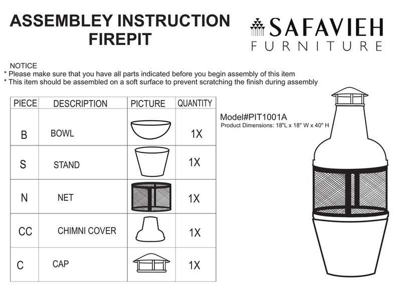
Safavieh Furniture
Safavieh Furniture PIT1001A Assembly instruction

Spark modern fires
Spark modern fires LBS-OD 72 - NG OWNER'S OPERATION AND INSTALLATION MANUAL
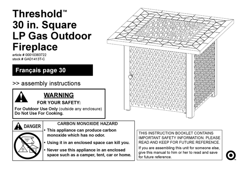
TRESHOLD
TRESHOLD GAD1413T-C Assembly instructions
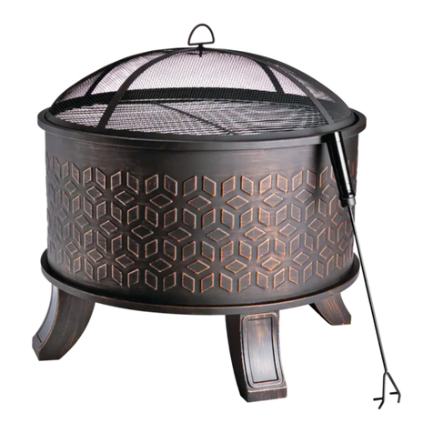
Canvas
Canvas 085-1258-0 Assembly instructions
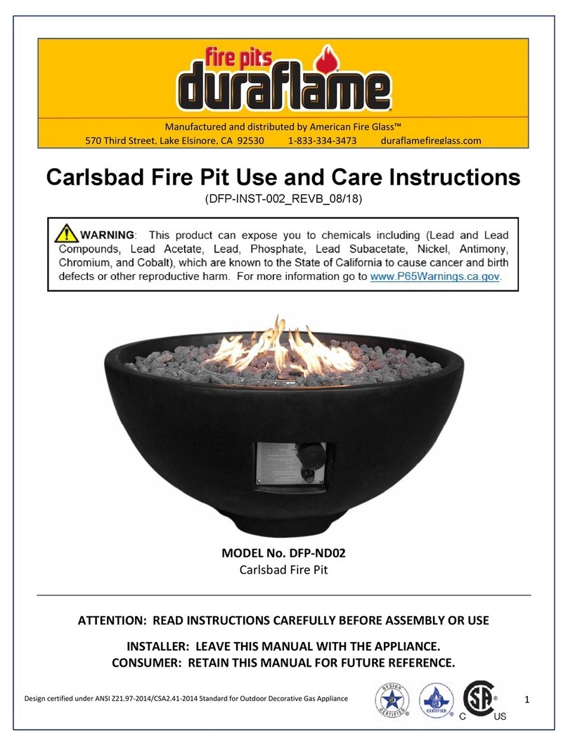
Duraflame
Duraflame Carlsbad DFP-ND02 Use and care instructions
tropitone
tropitone 401901RD manual
Endless Summer
Endless Summer GAD15275MG owner's manual

Outdoor GreatRoom Company
Outdoor GreatRoom Company Westport WP-INT installation instructions

pleasant hearth
pleasant hearth OFG201BT manual
Rebel
Rebel FIREPIT 160 Assembly and operating instructions

OVE
OVE BERLIN owner's manual
ROOMS TO GO
ROOMS TO GO Alamo DFP-FP20502 Use and care instructions
