GSI Group 700 Bu/Hr User manual

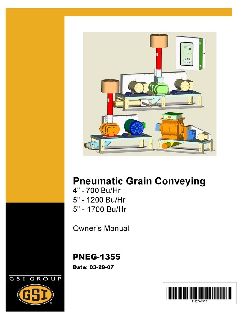
Pneumatic Grain Conveying
4" - 700 Bu/Hr
5" - 1200 Bu/Hr
5" - 1700 Bu/Hr
Owner’s Manual
PNEG-1563
Date: 07-27-09
PNEG-1563

2 Pneg-1563 4" & 5" Air Systems '07 Production

Pneg-1563 4" & 5" Air Systems '07 Production 3
Table of Contents
Contents
Chapter 1 Safety .................................................................................................................................. 5
Safety Guidelines ................................................................................................................5
Chapter 2 Decals ................................................................................................................................. 9
Chapter 3 Maintenance ..................................................................................................................... 11
Maintenance Schedule ......................................................................................................11
Chapter 4 Air System ........................................................................................................................ 12
Air System Capacities (Dry Shelled Corn) ........................................................................12
Capacity Chart (4" & 5" Systems) ..................................................................................... 12
Chapter 5 Installation ....................................................................................................................... 13
Air System Installation Instructions ...................................................................................13
Air System Capacities (Dry Shelled Corn) ........................................................................14
Air System Tubing Dimensions .........................................................................................15
Chapter 6 Dimensions ......................................................................................................................16
Elbow Angle Measurements .............................................................................................16
Chapter 7 Assembly ......................................................................................................................... 17
Air System Set-Up Procedures .........................................................................................17
Air System Control Box Definitions ...................................................................................20
Control Overview ...............................................................................................................20
Chapter 8 O/L CHART ....................................................................................................................... 23
4" & 5" Overload Set Chart ................................................................................................ 23
Chapter 9 Wiring ...............................................................................................................................24
Schematic - 230V-1PH ...................................................................................................... 24
Schematic - 230V/460V/575V-3PH ...................................................................................25
Schematic - Twin Air Systems ..........................................................................................26
Chapter 10 Operation and Management ......................................................................................... 27
Control Box Operational Procedures ...............................................................................27
Air System Operation Guidelines .................................................................................... 28
Chapter 11 Hook-Up Diagrams ........................................................................................................30
4 Pneg-1563 4" & 5" Air Systems '07 Production
Table of Contents
Chapter 12 Parts List ........................................................................................................................32
Blower Outlet Parts ..........................................................................................................33
4" (700) & 5" (1200) Standard Blower Parts ....................................................................34
4" & 5" Twin Blower Parts ................................................................................................36
5" (1700) Hi-Capacity Blower Parts .................................................................................38
5" (1700) Twin Hi-Capacity Blower Parts .........................................................................40
4" & 5" Blower Filters .......................................................................................................42
4" & 5" Airlock Parts .........................................................................................................44
Airlock Inlet Transition Assembly .....................................................................................46
Panel Module Assembly - Digital .....................................................................................47
Switch Panel Assembly - Standard ..................................................................................48
Switch Panel Assembly - Twin .........................................................................................49
Control Box Enclosure parts ............................................................................................50
Standard Control Panel Assembly - 230V - 1 Phase .......................................................52
Standard Control Panel Assembly 10-30 HP 230V - 3 Phase .........................................54
Standard Control Panel Assembly 40 HP 230V - 3 Phase ..............................................56
Standard Control Panel Assembly 10-40 HP 460V - 575V 3 Phase ...............................58
Twin Control Panel Assembly 230V - 1 Phase ................................................................60
Chapter 13 Troubleshooting ............................................................................................................62
Chapter 14 Couplings .......................................................................................................................64
How to Handle Handling Couplings .................................................................................64
Chapter 15 Warranty .........................................................................................................................65

Pneg-1563 4" & 5" Air Systems '07 Production 5
1.SAFETY
Safety Guidelines
This manual contains information that is important for you, the owner/operator, to know and
understand. This information relates to protecting personal safety and preventing equipment
problems. It is the responsibility of the owner/operator to inform anyone operating or working in
the area of this equipment of these safety guidelines. To help you recognize this information, we
use the symbols that are defined below. Please read the manual and pay attention to these
sections. Failure to read this manual and it’s safety instructions is a misuse of the equipment and
may lead to serious injury or death.
DANGER
WARNING
CAUTION
CAUTION
NOTE
This is the safety alert symbol. It is used to alert you
to potential personal injury hazards. Obey all safety
messages that follow this symbol to avoid possible
injury or death.
DANGER indicates an imminently hazardous situation
which, if not avoided, will result in death or serious injury.
WARNING indicates a potentially hazardous
situation which, if not avoided, could result in death or
serious injury.
CAUTION indicates a potentially hazardous situation
which, if not avoided, may result in minor or moderate
injury.
CAUTION used without the safety alert symbol indicates
a potentially hazardous situation which, if not avoided,
may result in property damage.
NOTE indicates information about the equipment that
you should pay special attention to.

6 Pneg-1563 4" & 5" Air Systems '07 Production
1. SAFETY
Follow Safety Instructions
Carefully read all safety messages in this manual and
on your machine safety signs. Keep signs in good
condition. Replace missing or damaged safety signs.
Be sure new equipment components and repair parts
include the current safety signs. Replacement safety
signs are available from the manufacturer.
Learn how to operate the machine and how to use
controls properly. Do not let anyone operate without
instruction.
Keep your machinery in proper working condition.
Unauthorized modifications to the machine may
impair the function and/or safety and affect machine
life.
If you do not understand any part of this manual and
need assistance, contact your dealer.
Stay Clear of Moving Parts and Air valves
Keep hands and feet awayfrom moving parts. Be sure
all people are clear of the equipment before start-up.
Wear close fitting clothing.
Keep all shields and covers in place at all times.
Stay clear of air blast for valve. Always wear safety
glasses to protect your eyes.
Install and Use equipment Properly
Ground all electrical equipment as well as the bin
itself.
Disconnect all power before servicing or opening
control box, adjusting, lubricating the equipment, or
opening the control box inner panel.
All electrical hook-ups should be in accordance with
local and National Electrical Code.
If three phase power is used, identify wild leg and wire
according to electrical diagram.
Never use plastic tubing for any lines carrying grain.

Pneg-1563 4" & 5" Air Systems '07 Production 7
1. SAFETY
Practice Safe Maintenance
Understand service procedures before doing
work. Keep area clean and dry.
Never lubricate, service, or adjust machine while
it is in operation. Stop and lock out power source
before making adjustments, cleaning, or
maintaining equipment.
Keep all parts in good condition and properly
installed. Fix damage immediately. Replace
worn or broken parts. Remove any build up of
grease, oil, or debris.
Prepare for Emergencies
Be prepared if fire starts.
Keep a first aid kit and fire extinguisher handy.
Keep emergency numbers for doctors,
ambulance service, hospital, and fire
department near your telephone.
Keep Emergency Equipment
Quickly Accessible.

8 Pneg-1563 4" & 5" Air Systems '07 Production
1. SAFETY
Wear Protective Clothing
Wear close fitting clothing and safety
equipment appropriate to the job.
Safety glasses should be worn at all times
to protect eyes from debris.
Wear gloves to protect your hands from
sharp edges on plastic or steel parts.
Wear steel toe boots to help protect your
toes from falling debris.
A respirator may be needed if a hog house
has poor ventilation. Waste fumes can be
toxic.
Remove all jewelry.
Tuck in any loose or dangling shoe strings.
Long hair should be tied up and back.
Wear hard hat to help protect your head.
Eye Protection
Gloves
Steel Toe Boots
Respirator
Hard Hat

Pneg-1563 4" & 5" Air Systems '07 Production 9
2.DECALS
Install safety decals on components as shown in the decal section. Always insure that safety
decals are in a place, easily readable, and in good condition. If a decal cannot be easily read for
any reason or has been painted over, replace it immediately. Contact your dealer or the
manufacturer to order a replacement decal free of charge.
For decal replacements contact GSI at:
1004 E. Illinois Street
Assumption, IL 62510
Ph: 1-217-226-442
DC-1749 DC-994
N10080
DC-1382
N10090

10 Pneg-1563 4" & 5" Air Systems '07 Production
2. DECALS
DC-1386 DC-995
N10080
DC-994
DC-995

Pneg-1563 4" & 5" Air Systems '07 Production 11
3.MAINTENANCE
Maintenance Schedule
Initial Start-Up
1. Roots - Flo Blower
2. Roots Blower
3. Air Lock Gearbox
4. Air Filter
5. V-belts
6. Chain
7. Tubing System
1. Oil level with middle of sight glass (DMC #MS5389 synth. oil).
2. Oil level to check plug.*
3. Oil level to check plug (SAE90).
4. Installed properly.
5. Tensioned and aligned.
6. Tensioned and aligned.
7. All couplers tight. All tubing connections have good fit. Tubing laid out
straight. Elbows fitting properly.
After First 10 Hours and Daily
1. Air Filter
2. V-belts
3. Tubing
1. Check for excessive dust build-up.
2. Check tension alignment.
3. Check all connections for leaks and signs of separating.
Weekly
1Chain
2. Blowers & Gearbox 1. Oil
2. Check oil levels.
1500 Hours (Synthetic Oil) - 500 Hours (Standard Oil)
1. Roots-Flo and Duraflow
2. Roots Blower.
1. Drain oil and replace with 1.5 Qts. of DMC #MS5389 synthetic oil. (Fill
to middle of sight glass).
2. Replace with 1.5 Qts. of Part No. MS5389. Add oil to both ends of
blower. (Fill to middle of both sight glasses).
Extended Shut Down
Disconnect Main Power Unit
1. Blower
2. Airlock
3. Chain
1. Remove inlet assembly and spray oil on lobes while rotating by hand,
to prevent rust. Keep hands and objects out of blower. Re-install inlet
assembly.
2. Coat interior with oil, while rotating by hand, to prevent rust. Re-install
weather cover.
3. Oil chain to prevent rust.

12 Pneg-1563 4" & 5" Air Systems '07 Production
4. AIR SYSTEM
Air System Capacities (Dry Shelled Corn)
Effective tube length is determined by adding the horizontal length, twice the vertical
height and 10 feet for every elbow of 45° or greater. Add five feet for each elbow less than
45°. Use the horizontal run and add the vertical rise of inclined systems to calculate the
effective length.
Capacity Chart (4" & 5" Systems)
Effective
Length
(Feet)
700 Bu/Hr
4" System (Roots) 1200 Bu/Hr
5" System (Roots) 1700 Bu/Hr
5" System (Roots-Flo)
10 HP
Motor 15 HP
Motor 20 HP
Motor 20 HP
Motor 30 HP
Motor 20 HP
Motor 30 HP
Motor 40 HP
Motor
50 525 800 850 1100 1300 1200 1600 1800
100 500 775 825 1075 1275 1175 1575 1775
150 475 750 800 1050 1250 1150 1550 1750
200 450 700 750 1000 1200 1100 1500 1700
250 400 650 700 925 1125 1025 1400 1600
300 350 575 625 825 1025 925 1275 1450
350 275 475 525 700 900 800 1100 1275
400 200 350 400 550 750 650 900 1050
450 - - 225 350 550 450 650 775
500 - - - - - - - 400

Pneg-1563 4" & 5" Air Systems '07 Production 13
5.INSTALLATION
Air System Installation Instructions
1. Determine the most convenient location for the airlock and blower. Take into consideration
the direction of the prevailing winds. It is important to locate the blower in as clean an
environment as possible. This greatly reduces the maintenance requirements on the air
filter system. When the distance between the airlock and blower is over 10 feet, it is best to
use galvanized pipe with short flex hose on the ends to couple the units together to keep
airflow restrictions to a minimum.
2. The noise level of the blower unit can be reduced by placing the unit behind a wall, barrier,
or in a small building. If this is done, make sure that the building has adequate ventilation
for both air intake and cooling of the blower and motor.
3.The grain discharge chuteon the airlockis assembledat the factoryso thatgrainmovement
isat90°tothelengthoftheskid.Thisorientationcanbechangedbyremovingthemounting
hardware at the base of the airlock and rotating the discharge chute to the preferred
direction. Be sure to keep the gasket in place between the skid and the discharge chute.
Note that the airlock itself is sealed to the skid surface and does not need to be moved to
redirect the discharge chute.
Note: A minimum of 10 feet is needed between the airlock discharge and the first elbow
in the system.
4.Determinethebest routing of the galvanizedsteelpipefrom the airlock tothestorageareas.
Use galvanized elbows for changing the grain direction. This will give better performance
and longer life than flexhose.
5. Bolt the tube mounting brackets to the desired location using at least two (2) mounting
brackets on the vertical wall and two (2) on the roof of the grain bin. The mounting brackets
can be formed to match existing hole patterns in the bin.
6. Determine the number and degree of arc required in the elbows. The 90° and 60° elbows
are standard - different lengths of arc can be cut from these standard elbows.
(See Page 16).
Note: A minimum of eight (8) feet between elbows is required for proper operation.
7. Cut the steel tubing to the required length and fasten it together with compression
couplings. The ends must be cut square to fit properly. Make sure that the stainless steel
gasket protecting sleeve is placed over the joint before tightening the coupler. Tighten the
three bolts on the coupler evenly or until the coupler flanges butt together (See Page 64).
8.Thesteeltubingcanbelaid underground,ontop ofthegroundorplacedon blocks. If placed
on blocks, the tubing must be supported every 15 feet. If placed underground, the tube
should enter and exit the ground at a 45° angle and be coated with a protective tar to
prevent corrosion.

14 Pneg-1563 4" & 5" Air Systems '07 Production
5. INSTALLATION
9. Measure the distance between the airlock and blower. Use flex hose or a combination of
flex hose and galvanized tubing to connect the units together. Notethat the grain discharge
chute on the airlock is tapered and that grain can discharge in either direction.
10. Install all tubing required to transfer grain to your storage areas.
11. To attach the deadhead deflector to the tubing, simply slide the deadhead deflector onto
the tubing and tighten the clamp provided. Flexible galvanized tubing can be attached to
the deadhead down spout if needed. If a cyclone isused, an elbow and mounting brackets
are needed.
12. Select a location to mount the electrical control box that is accessible and easily reached
should shut down of unit be necessary. It should be close enough to the blower to run the
30 feet of rubber pressure hose between the blower and the control box. Otherwise, a
longer length of hose must be ordered.
13. Before wiring or operating the Air System unit, read the control box description on pages
18 and 24 to understand the operation of the Air System control box. If the control box is
to be wired to remote equipment, review the wiring diagrams for proper hook-up.
Air System Capacities (Dry Shelled Corn)
Figure 5A

Pneg-1563 4" & 5" Air Systems '07 Production 15
5. INSTALLATION
Air System Tubing Dimensions
Figure 5B
Note: Add 10" to E dimension if roof elbow has been cut from a 90° Elbow.
System Size
Roof Angle
Reference Dimension
ABCD E
18' Dia 21' Dia 24' Dia 27' Dia 30' Dia 33' Dia 36' Dia 42' Dia 48' Dia
4" 25 31" 23" 47-1/2" 5-3/4" 7' 1" 8' 9" 10' 5" 12' 1" 13' 9" 15' 5" 17' 1" 20' 5" 23' 9"
30 29" 29" 46" 3-1/2" 7' 1" 8' 9" 10' 5" 12' 1" 13' 9" 15' 5" 17' 1" 20' 5" 23' 9"
35 27" 19" 45" 2-1/2" 8' 6" 10' 2" 11' 10" 13' 6" 15' 2" 16' 10" 18' 6" 21' 10" 25' 2"
5" 25 32-1/2" 22-1/2" 50" 4-1/2" 7' 8' 9" 10' 6" 12' 3" 14' 15' 9" 17' 6" 21' 24' 6"
30 30-1/2" 30-1/2" 49" 3-1/4" 6' 10" 8' 7" 10' 4" 12' 1" 13' 10" 15' 7" 17' 4" 20' 10" 24' 4"
35 28-1/2" 18-1/2" 48" 2-1/4" 8' 6" 10' 3" 12' 13' 9" 15' 6" 17' 3" 19' 22' 6" 26'
6" 25 32-1/4" 22-1/4" 51" 4-1/2" 7' 3" 9' 1" 10' 11" 12' 9" 14' 7" 16' 5" 18' 3" 21' 11" 25' 7"
30 30-1/4" 30" 50" 3" 7' 1" 8' 11" 10' 9" 12' 7" 14' 5" 16' 3" 18' 1" 21' 9" 25' 5"
35 28-1/4" 18" 49" 2" 8' 8" 10' 6" 12' 4" 14' 2" 16' 17' 10" 19' 9" 22' 4" 27'

16 Pneg-1563 4" & 5" Air Systems '07 Production
6. DIMENSIONS
Elbow Angle Measurements
801A025 8011235
8021120
8041124
L=10 + (.873 x Deg.)
L=10 + (.8813 x Deg.
802A015
L=10 + (.8911 x Deg.)
804A014

Pneg-1563 4" & 5" Air Systems '07 Production 17
7.ASSEMBLY
Air System Set-Up Procedures
1.The airfilter extension tube and housingare connected to the blower inlet by acompression
coupler. For extended filter life, if the pneumatic system is being operated in extremely dirty
conditions, a longer extension tube can be used between the blower inlet and the air filter.
BE SURE the air filter is positioned so that routine inspection and service can be performed.
2. Place the air filter element with pre-filter on the base and cover with the filter canister using
the 3/8" wing nut and washer. The wing nut does not need to be more than finger tight.
(See Figure 7A).
Figure 7A
3. Check the motor name plate for the correct motor frame size. Remove the hardware
shipped in the Motor Mounting Plate.Locate the motor on the mounting plate using the hole
pattern,whichalignswith the motorbase.Bolt the motorsecurely to themounting plate with
the supplied hardware that was previously removed. Loosen the (4) 1/2" flange head bolts,
which secure the motor Mounting Plate to the blower base. (See Figure 7B).
Figure 7B
Figure 7C
4. Place the specified pulley onto the motor and align it with the blower pulley.
(See Figure 7C).

18 Pneg-1563 4" & 5" Air Systems '07 Production
7. ASSEMBLY
5. See Figure 7D Place the matching set of V-belts on the pulleys.Tighten the belts by evenly
turning the cap screws clockwise. Belts should have 3/8" deflection at tenpounds pressure
per belt. (See Figure 7E).
Figure 7D Figure 7E
Too much tension on belts will cause blower damage.
6. Keeping the motor in proper alignment is necessary and can be accomplished by using an
open-end wrench to turn the nut on the take-up bolt closest to the rear of the motor. This
nut is located behind the flange of the blower base. Adjust if necessary. Tighten the (4)
flange head bolts that secure the motor mounting plate to the blower base. Re-Install Drive
Shield. (See Figure 7F)
Figure 7F Figure 7G
Rotate the motor by hand and listen for any rubbing or knocking by either the motor or
the blower. When the motor is wired, it must be checked for CCW rotation.
7. The oil level should be at the center of the sight glass on the blower. Add part number
MS5389 if required. DO Not Operate Blower Until Correct Oil Level is Indicated! The 4"
roots blower has sight glasses on both ends. Be sure oil levels are indicated on both sight
glasses. (See Figure 7G).
CAUTION
CAUTION

Pneg-1563 4" & 5" Air Systems '07 Production 19
7. ASSEMBLY
8. Using four (4) 5/16" x 3/4" flange head bolts, mount the motor to the airlock deck. Place the
specified pulley on to the motor shaft and align to pulley on gearbox. (See Figure 7H).
Figure 7H Figure 7I
9. Next, place the A-24 belt onto the pulleys. See Figure 7I Tighten the belt to its proper
tension of 3/8" deflection at ten pounds of pressure by pulling motor away from gearbox.
Tighten the four 5/16" flange bolts on the motor base. Replace the belt shield.
10. Check the oil level in the gearbox by removing the plug and noting if the oil is at this level.
Add SAE 80-90 gear lubricant if required. (See Figure 7J)
Figure 7J Figure 7K
11. Remove 1/4" pipe plug in gate valve pipe. Install gauge assembly and attach air hose.
(See Figure 7K)
THE SET-UP OF THE PNEUMATIC AIR SYSTEM IS NOW COMPLETE.

20 Pneg-1563 4" & 5" Air Systems '07 Production
7. ASSEMBLY
Air System Control Box Definitions
Figure 7L
Control Overview
The redesigned control box for air systems now incorporates short circuit protection for each
motor branch circuit. This is provided with circuit breakers which are the same as used in the
portable dryers. In addition, the contactors and overloads are now IEC style controls (portable
dryer parts also). This removes the need for separate thermal heater strips for the overloads. Be
aware that the power connections to the new style box are different. The incoming power still
enters at the lower right bottom of the box. The output power for the motors and remote control
connections now exit the hinge side of the box.
Confirm that the overloads are set to the values shown on the “Overload Set Chart”
on Page 23 before operating the system.
On single phase systems, connect the motor leads to terminals T1 and T3 on the
overloads. DO NOT use T2 since it already has a jumper preinstalled.
The remaining operations are the same as the previous control box design.
6. Digital Amp Meter
7. Tripped Overload
Indicator Light
8. 5 Amp Fuse
9. Control Switches
5. Air Pressure Limit
4. Start/Stop Switch
3. Control Circuit Ready
Indicator Light
2. Power “On” Indicator
Light
1. Air Pressure Gauge
CAUTION
Other manuals for 700 Bu/Hr
1
This manual suits for next models
2
Table of contents
Other GSI Group Industrial Equipment manuals

GSI Group
GSI Group PNEG-1521 Supplement

GSI Group
GSI Group CHE-10-VNC User manual

GSI Group
GSI Group PNEG-1088 User manual

GSI Group
GSI Group SCR Series User manual

GSI Group
GSI Group PNEG-369 User manual

GSI Group
GSI Group PNEG-1421 Supplement

GSI Group
GSI Group Agri-Alert 128 Touch Manual

GSI Group
GSI Group 700 Bu/Hr User manual

GSI Group
GSI Group Agri-Alert 128 Touch User manual

GSI Group
GSI Group Alpha 40 Series User manual