BobsCNC Evolution Series User manual
Evolution 4
Assembly Manual
Rev. 1.06

1
The Evolution Series CNC Router
Welcome to the Family.
We’re excited that you purchased the Evolution 4 CNC Router Kit
from BobsCNC, and we know you’re just as excited to put it
together. This manual gives you step by step instructions to
ensure your success in assembling the Evolution 4 CNC Router
and provides all the information you need to get your machine up
and running.
Before beginning the assembly, take the time you need to
completely review the manual. It’s good to be familiar with the
entire assembly process before diving in. Be sure to check out the
recommended tools you’ll need for the assembly.
Welcome to the BobsCNC family. It’s time to… Unleash Your
Creativity!
Version 0.37

2
Table of Contents
Information/Warning Boxes........................................................................................................................................5
Safety Precautions and Warnings.............................................................................................................................6
Getting Started.................................................................................................................................................................7
Required Tools:............................................................................................................................................................7
To Operate the EVOLUTION 4 CNC Router, you need will need:.............................................................7
Recommended for the electronic setup include: ...........................................................................................7
Assembly Recommendations: ....................................................................................................................................8
Required Wood Components................................................................................................................................9
Required Hardware................................................................................................................................................. 10
Z Carriage Assembly............................................................................................................................................... 12
Y Carriage Assembly ................................................................................................................................................... 22
Required Wood Components............................................................................................................................. 22
Required Hardware................................................................................................................................................. 23
Illustrated Step by Step Instructions ................................................................................................................ 31
Gantry Assembly........................................................................................................................................................... 38
Required Wood Components............................................................................................................................. 38
Required Hardware................................................................................................................................................. 39
Illustrated Step by Step Instructions ................................................................................................................ 42
Front View (Right Hand Side) Completed...................................................................................................... 57
X Frame Instructions ................................................................................................................................................... 82
Required Wood Components............................................................................................................................. 82
Required Hardware................................................................................................................................................. 83
Illustrated Step by Step Instructions ................................................................................................................ 83
Final Assembly............................................................................................................................................................... 91
Wood Components (Included with Kit)........................................................................................................... 91

3
Required Hardware................................................................................................................................................. 91
Illustrated Step by Step Instructions ................................................................................................................ 93
Spoilboard installation (optional) ........................................................................................................................126
Completed Views .......................................................................................................................................................128
Tramming......................................................................................................................................................................133
Congratulations! You Just Completed the Assembly of Your Evolution 4. ..........................................135
Appendix .......................................................................................................................................................................136
Evolution 4 Firmware Values.............................................................................................................................136
Evolution Washer Dimensions..........................................................................................................................137
Evolution 4 Spoilboard Drawing......................................................................................................................138

4
EVOLUTION 4 Specifications
Laser cut 6mm Baltic Birch Frame components.
Fully Engineered Frame with rigid Box and Beam Gantry.
Fully supported 5/16-inch stress proof steel Rails with SG20U
Bearings.
GT2 Belt Drive on X and Y axis.
2 mm pitch, 4 start Acme Threaded Rod on Z axis.
Home Switches with Self Squaring Gantry.
¾” MDF Spoilboard with Inserts (Optional).
Accuracy .002 to .004 inch.
The assembled footprint:
Length: 32" (838 mm)
Width: 39" (994 mm)
Height: 20.9" (530 mm)
Assembled Weight:
48 lbs.
Cutting Area:
X: 24" (610 mm)
Y: 24" (610 mm)
Z: 3.3" (85 mm)

5
Safety is the First Priority. Always wear proper protective
equipment and use "safety sense" when assembling and
operating your Evolution 4 CNC Router.
Information/Warning Boxes
CAUTION Indicates a possible risk of
injury that can result from failure to follow this
instruction
WARNING Indicates the possible damage
to the machine, its components, the work
piece, or injury that can result from failure to
follow this warning.
DANGER Indicates a serious risk of bodily
harm, injury and death. This is a serious
warning and should not be ignored. Any work
must be carried out with extreme caution.
TIPs Contains helpful information,
shortcuts, and hints to simplify assembly and
make machine operation easier and safer.
TIP
T

6
Safety Precautions and Warnings
Evolution Series CNC Routers have a 110 v. power supply and use bits that spin at
28,000 rpm with cutting edges that are sharp and hazardous. The operator must
understand the potential hazards and is responsible to take appropriate safety
precautions before operating the Router.
•Only use extension cords rated for 20 amps plugged into a dedicated outlet.
•Inspect the machine before every use for maintenance issues: loose fasteners,
belts, etc.
•Do not operate the machine with dull or damaged router bits.
•Always unplug machine after each use and when cleaning the router or changing
router bits.
•Remove rings, bracelets, watches, necklaces before using the machine.
•Wear snug fitting clothing and/or roll up long sleeves to prevent snagging.
•Use appropriate personal protective equipment (PPE) when operating machine
including safety glasses and hearing protection.
•Keep hands, hair and clothing away from the moving parts of the machine.
•Do not operate the machine when under the influence of alcohol or prescription
medications.
•Make certain the workpiece is clamped securely in place before starting the
machine.
•Never leave the machine running unattended.
•Children must be supervised by adults when operating the machine.
•Do not operate the machine in the presence of flammable materials.
•Keep floors clean, dry, and free of debris to eliminate slip and/or trip hazards.
•Have a suitably rated fire extinguisher on hand when the machine is in operation.

7
Getting Started
Required Tools:
A pair of long nose pliers.
Diagonal Cutters or sharp knife to trim nylon ties.
Calipers or measuring tape to measure part placement.
Small standard screwdriver to connect electronics.
#2 Phillips screwdriver to mount home switches and stepper motors.
#3 Phillips screwdriver to build the main components.
220 grit sandpaper to remove laser marks on wood pieces (if desired).
LOCTITE 242™thread lock (fingernail polish can be used as a substitute).
Set of Metric Sockets and SAE Wrenches.
Set of Metric and SAE Allen Wrenches.
To Operate the EVOLUTION 4 CNC Router, you need will need:
Computer with control software for GRBL.
Materials for Projects.
1/4” Shaft Router bits.
Recommended for the electronic setup include:
Multimeter to correctly connect the Power Supply and to set the current for
the Stepper Motors (a great tool for general electronic trouble shooting).

8
Assembly Recommendations:
Use a large, flat, clean work surface for assembling your EVOLUTION 4.
All Screws (unless noted) should be installed snug, then rotated 1-2 ½
turns.
Light sanding may be required to remove any marks made by the laser.
Painting, or applying stain with a clear coat will provide extra protection to
the wood components
Try using strips of 1 inch blue painters’ tape behind the T-Slots to help hold
the Nuts in place during assembly.
Lock Nuts are never used to secure components that have T-Slots. They
are only used to mount components where the Nut is not held in a
T-Slot.
CAUTION This kit contains numerous small
components that pose a choking risk for small
children and pets. Keep kit pieces in a secure
location out of the reach or small children and pets.

9
Z Spindle Mount Assembly
Required Wood Components
Part #
Description
Qty
Photo
Z1
Frame Mount Support
2
Z2
Z Frame Support
2
Z3
Z Frame
1
Z4
Spindle Bottom Mount
1
10
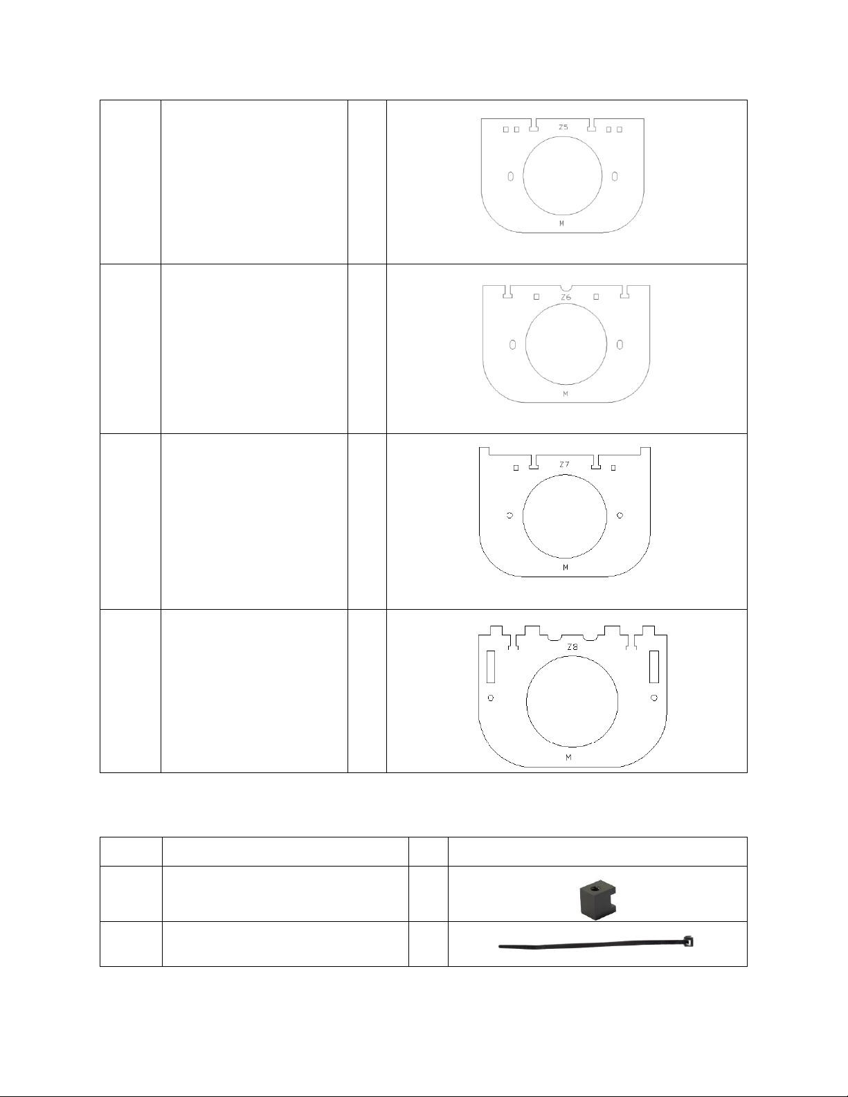
Z5
Spindle Interlock Bottom
1
Z6
Spindle Interlock Top
1
Z7
Spindle Top Mount
1
Z8
Spindle Support
1
Required Hardware
Part #
Description
Qty
Photo
ZD2
Acme Block Nut
1
H31
8“ Zip Tie
1

11
H39
M6 x 30 Machine Screws
4
H18
M6 Locknuts
4
H40
Eccentric Adjustment Spacer
4
H41
Eccentric Washer
4
H42
Bearing Fender Washer
4
H44
SG20U Bearings
4
H38
M4 x 30 Machine Screws
2
H14
M4 x 16 Screws
25
H15
M4 Nuts
25
H47
M4 Lock Nuts
2

12
Z Carriage Assembly
The Z Carriage Assembly holds the Router securely in a carriage that travels
up and down the Z-axis on a set of Rails. These first steps will show you
how to build the Spindle (Router) Mount.
NOTE: The Z Frame has alignment marks that are used to snug the SG20U
Bearings to the Rails and later to tram the Router. When assembling the Z
Carriage, it is important that the adjustment marks face toward the Spindle
Mount as shown in the following photos.
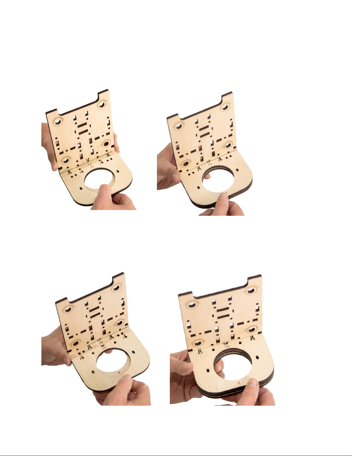
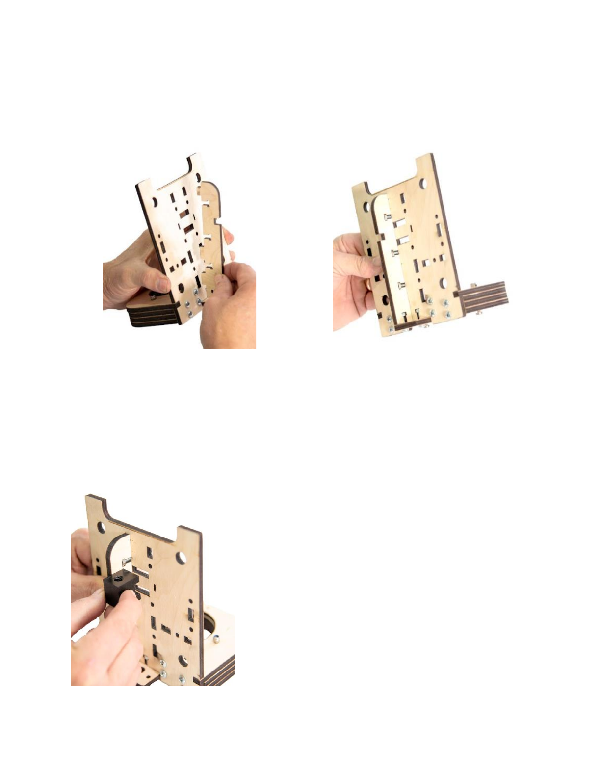
Step 1 Attach Spindle Bottom Mount (Z4) to the Z Frame (Z3) with
three M4 x 16 Machine Screws and Nuts as shown.
13
Step 2 Attach Spindle Interlock Bottom (Z5) to the Z Frame Assembly
with two M4 x 16 Machine Screws and Nuts as shown.
Step 3 Attach Spindle Interlock Top (Z6) to the Z Frame Assembly with
two M4 x 16 Machine Screws and Nuts as shown.
14
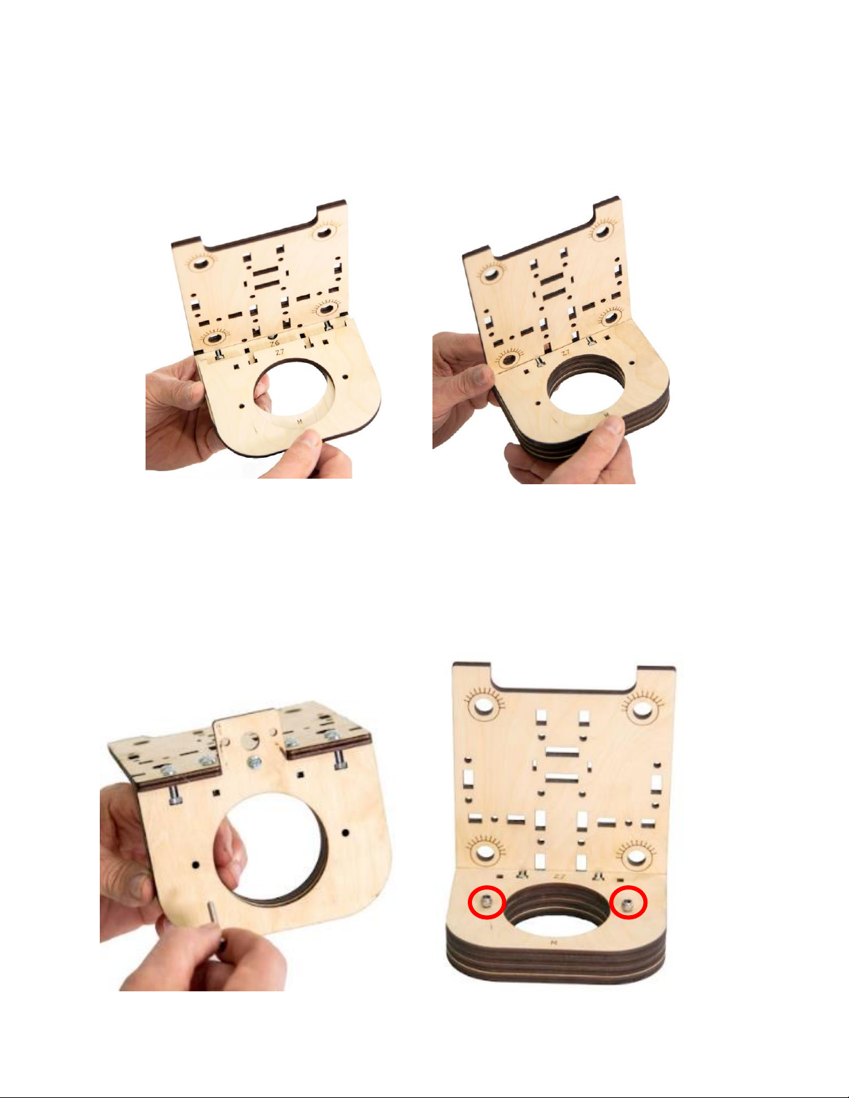
Step 4 Attach Spindle Top (Z7) to the Z Frame Assembly with two
M4 x 16 Machine Screws and Nuts as shown.
Step 5 Secure the Spindle Bottom Supports together with two M4 x 30
Machine Screws and Locknuts as shown. Do not fully tighten the nut.
15
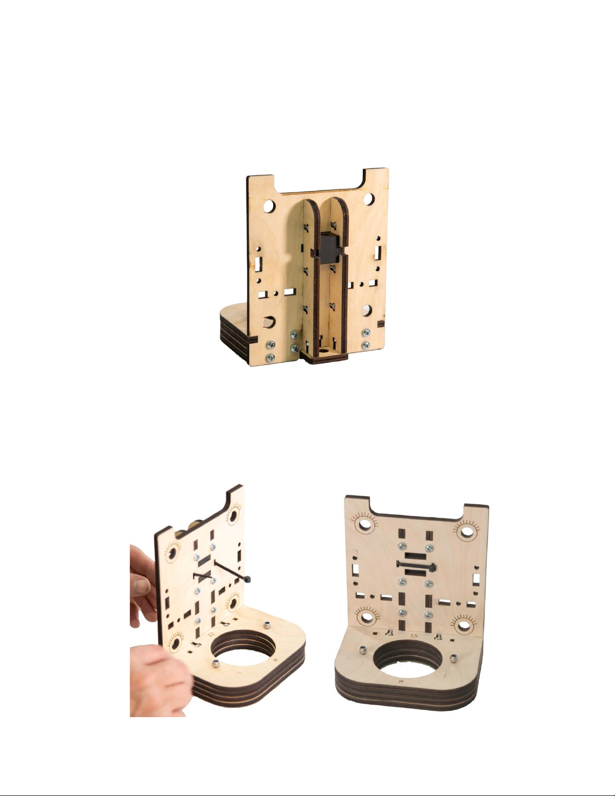
Step 6 Attach the Z Frame Support (Z2) to the Spindle Assembly with
four M4 x 16 Machine Screws and Nuts as shown.
Step 7 Fit the tabs on the Acme Block Nut (A) into the slots on the
back side of the Frame Assembly as shown.
16
Step 8 Attach the second Frame Support (Z2) to the Spindle Top Plate
Assembly with four M4 x 16 Machine Screws and Nuts as shown. Be careful
to keep the Acme Block Nut securely in place.
Step 9 Wrap an 8” Zip Tie around the Frame Supports as shown. Make
sure the Zip Tie Lock is positioned on the Router side of the Assembly.

17
Test fit the Router in the Support
Assembly as shown. This will help align
the interlocking center pieces prior to final
assembly and tightening. Remove the
Router after dry fitting is completed.
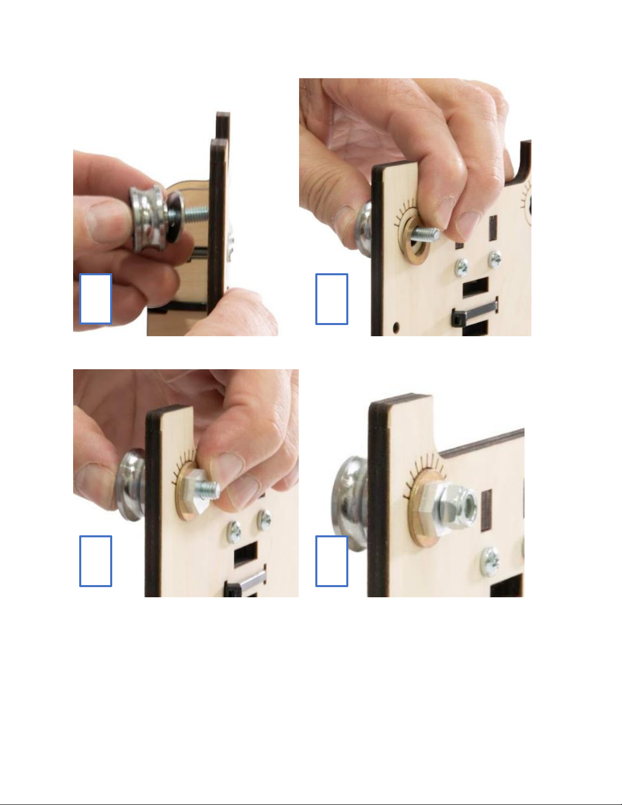
Step 10 Attach four SG20U Bearing Assemblies to the Z Frame.
When putting the Bearing Assembly together,
make sure the hub on the Bearing faces the
wood. IMPORTANT: The Screw must be
oriented so that the Nut is visible when looking
at the back of the carriage (see photo below).
TIP
T
TIP
T
Hub

18
NOTE: Bearing Assembly with Eccentric Adjustment Spacer Order:
Machine Screw Head, Bearing (with hub facing toward the Bearing
Washer), Bearing Washer, Eccentric Washer, Eccentric Adjustment
Spacer, Locknut.
Prior to putting the Bearing Assembly together
mark the point of the inboard edge of the
Eccentric Adjustment Spacer using a
permanent marker as shown below. This
mark will help orient the Nut for tramming.
TIP
T
Mark this
inboard point
19
1
2
3
4
This manual suits for next models
1
Table of contents
Other BobsCNC Industrial Equipment manuals


