Body flex BRM8000 User manual
For use under U.S. Patent numbers 61592, D459773, D438264

This page intentionally left blank
General Information
BRM8000/8800 Page 1
Warranty
Body Flex Sports warrants your product for
a period of 1 year for the frame and 90 days
on all parts if the item is used for the intended
purpose, properly maintained and not used
commercially. Any alterations or incorrect
assembly of the product will void this warranty.
Proof of purchase must be presented for any
warranty validation (no exceptions). This
warranty applies to the original purchaser only
and is not transferable.
This warranty does not cover abuse or defects
caused during use, storage or assembly.
During the warranty period, Body Flex Sports
reserves the right to:
a). provide replacement parts to the
purchaser in an effort to repair the item.
b). repair the product returned to our
warehouse (at the purchaser’s cost).
c). replace the product if neither of the two
previously mentioned actions effect repair.
This warranty does not cover normal wear and
tear on upholstery.
Questions
If you have any questions concerning the
assembly of your item or if any parts are
missing, please DO NOT RETURN THE
ITEM TO THE STORE OR CONTACT THE
RETAILER. Our dedicated customer service
staff can help you with any questions you may
have regarding the assembly of this unit and
can also mail you replacement parts.
Customer Support
Customer Support is open 9:00 a.m. to 5:00
p.m. (Pacific Time) Monday through Friday.
Please contact us by any of the following
means.
Body Flex Sports, Inc.
21717 Ferrero Parkway, Walnut, CA 91789
Telephone: (888) 266 - 6789
Fax: (909) 598 - 6707
Email: info@bodyflexsports.com
Safety
Before you undertake any exercise program,
please be sure to consult with your doctor.
Frequent strenuous exercise should be
approved by your doctor and proper use
of your product is essential. Excessive or incorrect
training may result to health injuries. Please read
this manual carefully before commencing the
assembly of your product or starting to exercise.
• Please keep all children away from this item
when in use. Do not allow children to climb or
play on them when they are not in use.
• Supervise teenagers while they use this unit.
• For your own safety, always ensure that there
is at least 3 feet of free space in all directions
around your product while you are exercising.
• Regularly check to see that all nuts, bolts and
fittings are securely tightened. Periodically
check all moving parts for obvious signs of
wear or damage.
• Clean only with a damp cloth, do not use
solvent cleaners. If you are in any doubt, do
not use your product; contact CUSTOMER
SUPPORT.
• Before use, always ensure that your product
is positioned on a solid, flat surface. If
necessary, use a rubber mat underneath to
reduce the possibility of slipping.
• Always wear appropriate clothing and
footwear such as training shoes when
exercising. Do not wear loose clothing that
could become caught in moving parts during
exercise.
• Do not use this unit if it is not functioning
properly or if it is not fully assembled.
• Do not use this unit for commercial purposes.
This unit is for home use only.
Storage and Use
Your product is intended for use in clean
dry conditions. You should avoid storage in
excessively cold or damp places as this may
lead to corrosion and other related problems.
Weight Limit
Your product is suitable for users weighing:
300 pounds or less.
• Before use, you must read and understand all
instructions & warnings stated in this Owner’s
Manual as well as posted on the equipment.
• It is the facility owner’s responsibility to properly
instruct users on the proper operation of the
equipment and to warn them of the potential
hazards.
• If at any time during exercise you feel faint, dizzy
or experience pain, stop and consult your
physician.
Assembling Tools
- Ruler with both metric and English measurements
- 2 x Adjustable Wrenches
- 1 x Philips (”Crosshead”) Screw Driver
•
Any adjustment devices that could interfere with
the user's movement on this unit should not be
left projecting.

Hardware & Tool List
Page 2
#38. Hex Bolt (M8x45 mm)
(4 Pieces)
#51. Bolt (M8x50 mm)
(4 Pieces)
#54. Screw (ST4.2X19 mm)
(2 Pieces)
#43. Screw (M5x10 mm)
(4 Pieces)
#55. Screw (ST4.2x25 mm)
(1 Piece)
#10. Spring Washer (M8)
(4 Pieces)
#16. Arc Washer (M8)
(4 Pieces)
#20. Special Washer
(M19xφ25 mm) (2 Pieces)
Pre-assembled
#30. Washer (M8,t1.5)
(13 Pieces)
Pre-assembled (7 Pieces)
#31. Arc Washer (M8,R30)
(2 Pieces)
#23. Washer (M8,t2.0)
(2 Pieces)
#62. Washer (M4)
(6 Pieces)
Pre-assembled
#72. Washer (M10,φ20)
(3 Pieces)
#17. Nylon Nut (M8) (9 Pieces)
Pre-assembled (3 Pieces)
#42. Nylon Nut (M10) (2 Pieces)
#39. Knob Nut (M8) (4 Pieces) #63. Knob Bolt (M1
Pre-assembled
6x27 mm) (1 Piece) #66. Knob Nut (M10) (1 Piece)
#11. Bolt (M8x25 mm)
(2 Pieces)
#14. Carriage Bolt (M8x43 mm)
(4 Pieces)
#02. Screw (M4x12 mm)
(6 Pieces)
Pre-assembled
#22. Hex Bolt (M8x16 mm)
(2 Pieces)
#34. Screw
(ST.4.2x16 mm)
(6 Pieces)
#35. Hex Bolt (M8x75 mm)
(2 Pieces)
#29. Bolt (M8x16 mm)
(6 Pieces)
Tool. S17-19
(2 Pieces)
Tool. S13-14
(1 Piece)
Tool. S13-14-15
(1 Piece)
Tool. S6 (1 Piece)
Tool. S5 (1 Piece)
Bolts
Washers
Nuts
Knobs
Tool
a moment to familiarize yourself with these items.
PLEASE NOTE: some of these parts may have already been pre-assembled on your unit.
The following hardware is used to assemble your unit. Please take
#77. Hex Bolt (M10x55 mm)
(2 Pieces)
Pre-assembled
BRM8000/8800

Page 3
BRM 3670 Stride Cycle Page ?
Parts Listing
The following parts list describes all of the parts illustrated on the
exploded diagram on the following page. Please note, most of
these parts are already pre-assembled on your unit.
# Description # Description
01 Monitor
02 Screw (M4x12 mm)
03 End Cap (φ25x16 mm)
04 Hand Pulse Bar
05 Washer (M6)
06 Screw (ST4x19 mm)
07 Hand Pulse Sensor
08 Foam (φ23x500 mm)
09 Wire Cap
10 Spring Washer (M8)
11 Bolt (M8x25 mm)
12 End Cap (φ32x22xφ50 mm)
13L/R Left/Right Handle Bar
14 Carriage Bolt (M8x43 mm)
15 Foam (φ30x630 mm)
16 Arc Washer (M8)
17 Nylon Nut (M8)
18 Front Stabilizer
19 Spacer
20 Special Washer (M19xφ25 mm)
21 Spacer
22 Hex Bolt (M8x16 mm)
23 Washer (M8,t2.0)
24 Spacer
25L/R Left/Right Couple Bar25L/R Left/Right Couple Bar
26F/R Left Couple Bar Shroud
27F/R Right Couple Bar Shroud
28 Center Post
29 Bolt (M8x16 mm)
30 Washer (M8,t1.5)
31 Arc Washer (M8,R30)
32 End Cap (30x60 mm)
33L/R Right Pedal Tube Shroud (Front)
34 Screw (ST.4.2x16 mm)
35 Hex Bolt (M8x75 mm)
36L/R Left/Right Pedal Tube
37L/R Left/Right Pedal
38 Hex Bolt (M8x45 mm)
39 Knob Nut (M8)
40 Spacer
41 Washer (M10,φ32)
42 Nylon Nut (M10)
43 Screw (M5x10 mm)
44U/D Right Pedal Tube Shroud (Rear)
45U/D Left Pedal Tube Shroud (Rear)
46L/R Left Pedal Tube Shroud (Front)
47L/R Main Frame Shroud 1
48L/R End cap for Front Stabilizer
49 Washer (M5)
50 Monitor Wire (Middle)
51 Bolt (M8x50 mm)
52 Rear Stabilizer
53 End Cap for Rear Stabilizer
54 Screw (ST4.2X19 mm)
55 Screw (ST4.2x25 mm)
56F/R Center Post Shroud
57 Main Frame Shroud 2
58 Spacer
59 Monitor Wire (Lower)
60 Main Frame
61 Hand Pulse Wire
62 Washer (M4)
63 Knob Bolt (M16x27 mm)
64 Seat Post Sleeve64 Seat Post Sleeve
65 Seat Post
66 Knob Nut (M10)
67 End Cap (口38 mm)
68 U Bracket
69 Horizontal Seat Bar
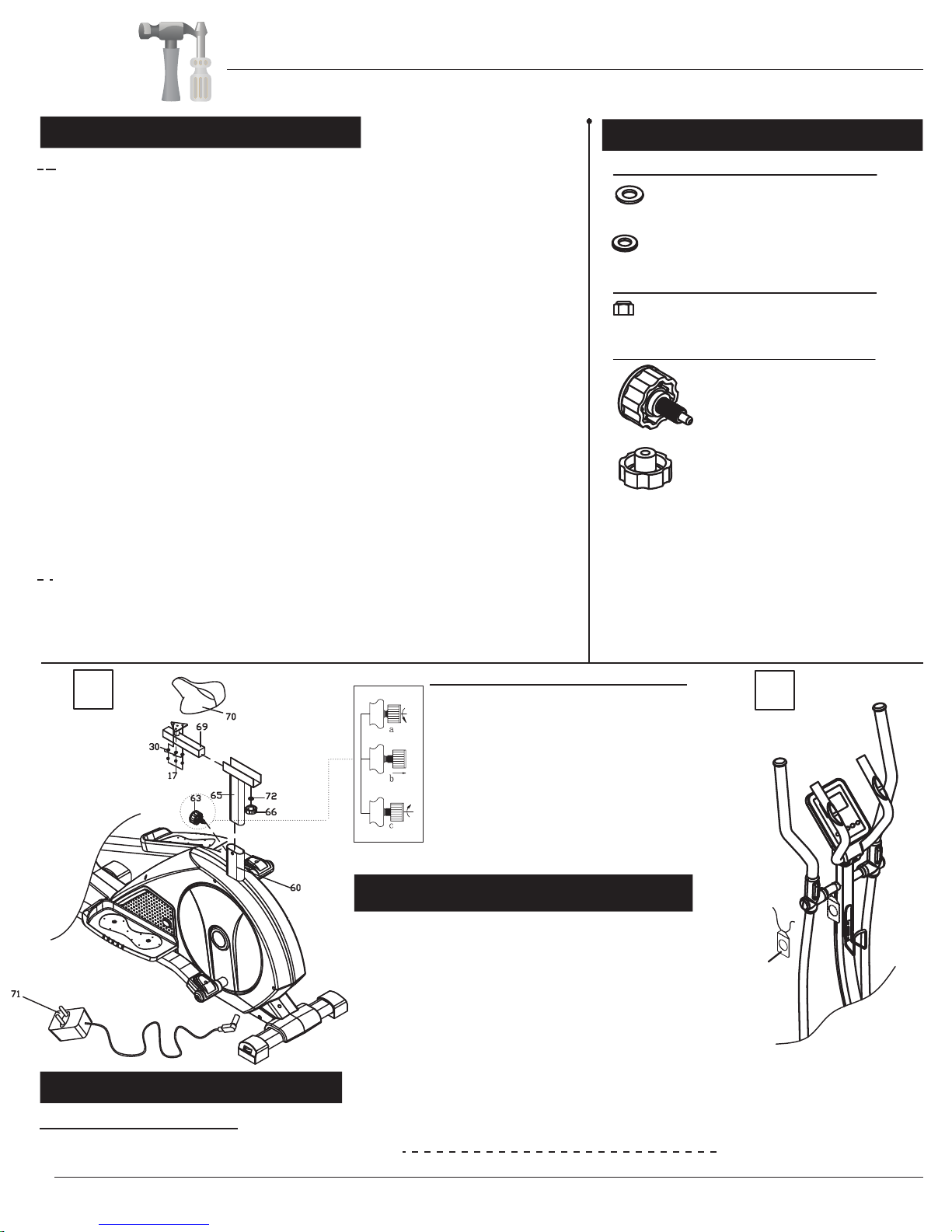
70 Seat
71 AC Adapter
72 Washer (M10,φ20)
73 Water Bottle Holder
74L/R Left/Right Crank
75 Monitor Wire (Upper)
76 MP3 Wire
77 Hex Bolt (M10x55 mm)
78 Pedal Connection Joint
79 Bushing
80 Bag
BRM8000/8800

Page 4
Exploded Diagram
The following diagram is provided to help you familiarize yourself with the parts and
hardware that will be used during the assembly process. Please note that not all of the
parts and hardware you see here will be used while you are assembling the machine
because some of these items are already pre-installed. Please continue to the next
page to begin the assembly process and use this page only as a reference guide for
parts and hardware.
80
BRM8000/8800
Page 5
A s s e m b l y S t e p 1
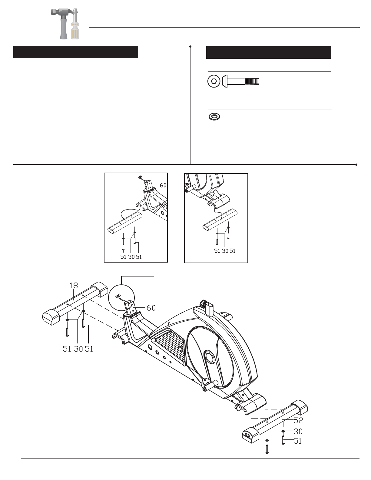
With the help of an assistant, attach the Front Stabilizer
(#18) to the front of the Main Frame (#60) by inserting two
Bolts (#51) through two Washers (#30) and up through
the Front Stabilizer (#18).
Next, attach the Rear Stabilizer (#52) to the back of the Main
Frame (#60) by inserting two Bolts (#51) through two
Washers (#30) and up through the Rear Stabilizer (#52).
Remove the Bolts (#51), Washers (#30) and Tubes that
are pre-assembled on the bottome of the front and rear
of the Main Frame (#60) and set them aside. The Bolts
and Washers will be used later in this step. The two tubes
are the packing material to protect the production.
Hardware Required
Bolts
Washers
#51. Bolt (M8x50 mm)
(4 Pieces)
#30. Washer (M8,t1.5)
(4 Pieces)
Make sure this wire is exposed and hanging out before proceeding
to the next step. If it has fallen inside the tube, use a
bent wire to “fish” it out.
Front Rear
Assembly Instructions
BRM8000/8800
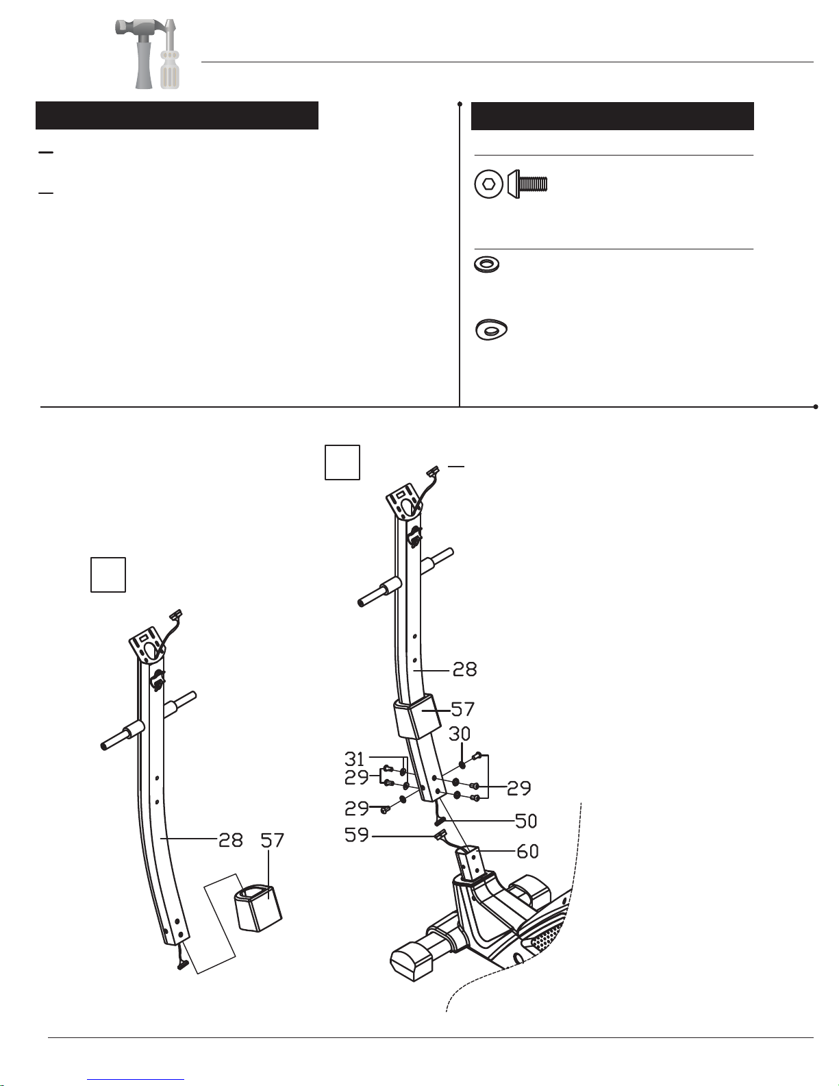
A s s e m b l y S t e p 2 Hardware Required
Bolts
Washers
#29. Bolt (M8x16 mm)
(6 Pieces)
#30. Washer (M8,t1.5)
(4 Pieces)
#31. Arc Washer (M8,R30)
(2 Pieces)
55
40
1 2 3 4
55
40
1 2 3 4
Make sure this wire is hanging out before
assembling the Center post (#28).
Page 6
Assembly Instructions
With the help of an assistant, slide the Main Frame Shroud 2
(#57) onto the Center Post (#28).
Next, connect Monitor Wire (Lower) (#59) to Monitor Wire
(Middle) (#50). Then, slip on the Center Post (#28) (with Main
Frame Shroud 2 (#57) now also attached) over the front protruding
post of the Main Frame (#60).
To attach the Center Post (#28), lift up the Main Frame Shroud 2
(#57). Secure the back of the post using two Bolts (#29) and
two Washers (#30); and then secure the front of post using two
Bolts (#29) and two Arc Washers (#31). Secure the left and right
sides using two Bolts (#29) and two Washers (#30).
You may now gently release the Main Frame Shroud 2 (#57)
(which should cover the Bolts and Washers).
A
B
A.
B.
BRM8000/8800

A s s e m b l y S t e p 3
Bolts
Washers
Nuts
#22. Hex Bolt (M8x16 mm)
(2 Pieces)
#35. Hex Bolt (M8x75 mm)
(2 Pieces)
#10. Spring Washer (M8)
(2 Pieces)
#20. Special Washer
(M19xφ25 mm) (2 Pieces)
#23. Washer (M8,t2.0)
(2 Pieces)
#72. Washer (M10,φ20)
(2 Pieces)
#42. Nylon Nut (M10) (2 Pieces)
Hardware Required
#30. Washer (M8,t1.5)
(2 Pieces)
#17. Nylon Nut (M8) (2 Pieces)
#77. Hex Bolt (M10x55 mm)
(2 Pieces)
C
Page 7
A. Please use illustration “A” below as reference.
On the left side, ensure that one Special Washer (#20) is present (already pre-
assembled) on the Center Post (#28).Then slide on the Left Couple Bar
(#25L), followed by one Washer (#23), one Spring Washer (#10), and secure
with one Hex Bolt (#22).
On the right side, ensure that one Special Washer (#20) is present (already pre-
assembled) on the Center Post (#28).Then slide on the Right Couple Bar
(#25R), followed by one Washer (#23), one Spring Washer (#10), and secure
with one Hex Bolt (#22).
B. Referring to illustration “B”, ensure that the Pedal Connection Joint (#78)
present (already pre-assembled) on the Left Crank (#74L). Align the holes on
the Pedal Connection Joint (#78) to the Left Pedal Tube (#36L) by inserting one Hex
Bolt (#77), one Washer (#72) and one Nylon Nut (#42). Repeat this process on the
other side using the Pedal Connection Joint (#78) and Right Pedal Tube (#36R).
C. Referring to close-up illustration “C”, align the holes on the Left Couple Bar
(#25L) to the front of the Left Pedal Tube (#36L) by inserting one Hex Bolt (#35)
through the Left Pedal Tube (#36L), the Left Couple Bar (#25L) and secure with
one Washer (#30) and one Nylon Nut (#17). Repeat this process on the right side.
Remove the Special Washer (#20) that are preassembled on the Axle of the
Center Post (#28) and set them aside as they will be used later in this step.
A
B
Assembly Instructions
BRM8000/8800

Assembly Instructions
Page 8
A s s e m b l y S t e p 4
44U
44D
45U
45D
27F
26F
A s s e m b l y S t e p 5
Bolts
Washers
Nuts
Knobs
#38. Hex Bolt (M8x45 mm)
(4 Pieces)
#43. Screw (M5x10 mm)
(4 Pieces)
#16. Arc Washer (M8)
(4 Pieces)
#17. Nylon Nut (M8) (4 Pieces)
#39. Knob Nut (M8) (4 Pieces)
#14. Carriage Bolt (M8x43 mm)
(4 Pieces)
#34. Screw
(ST.4.2x16 mm)
(6 Pieces)
Bolts
Hardware Required
Hardware Required
Attach the Left Pedal (#37L) onto the Left Pedal Tube (#36L)
by inserting two Hex Bolts (#38) through the aligned holes
and securing with two Knob Nuts (#39). Repeat this process
on the other side using Right Pedal (#37R).
Next, attach the Left Pedal Tube Shroud (Front) (#46L/#46R)
to the front of the Left Pedal Tube (#36L). Please make sure
the two parts are aligned and flush (you may hear the parts
gently “snapping” in place), then secure using three Screws
(#34). Then, at the back of the Left Pedal Tube (#36L),
attach the Left Pedal Tube Shroud (Rear) (#45U/#45D) and
secure using two Screws (#43). Repeat this process on the
other side using Right Pedal Tube Shroud (Front) (#33L/#33R)
and Right Pedal Tube Shroud (Rear) (#44U/#44D).
On the left side, insert the Left Handle Bar (#13L) onto the
Left Couple Bar (#25L). Align the holes and insert two
Carriage Bolts (#14) and securing with two Arc Washers
(#16) and two Nylon Nuts (#17). Repeat this process on the
other side using Right Handle Bar (#13R).
Next, attach the Left Couple Bar Shroud (#26F/#26R)
over the assembled Left Handle Bar (#13L). Repeat this
process on the other side using the Right Couple Bar Shroud
(#27F/#27R).
BRM8000/8800

R
Connect the Monitor Wire (Upper) (#75) to the Monitor
Wire (Middle) (#50) and tuck the wires in the hole of the
Center Post (#28) to avoid pinching them.
Attach the Monitor (#01) to the Center Post (#28) by
aligning the holes and securing with four Screws (#02)
inserted through four Washers (#62).
Attach the Hand Pulse Bar (#04) by aligning it to the
horizontal catch located on the Center Post (#28) and
secure using two Bolts (#11) inserted through two Spring
Washers (#10).
Attach the Center Post Shroud (#56L/#56R) over the
Center Post (#28) and Hand Pulse Bar (#04) as
shown below and secure using two Screws (#54) on the
top and one Screw (#55) on the bottom.
Attach the Water Bottle Holder (#73) by aligning it to
the holes on the Center Post (#28) and secure using
two Screws (#02) inserted through two Washers (#62).
Connect the Hand Pulse Wire (#61) to the hole on the
back of the Monitor (#01).
The MP3 Wire (#76) is for your workout entertainment.
Connect one end to the corresponding hole on the
Monitor (#01) and the other end to a compatible MP3
player of your choice.
Remove the Screws (#02) and Washers (#62) that are
pre-assembled on the back of the Monitor (#01) as set
them aside as they will be used later in this step.
Remove the Screws (#02) and Washers (#62) that are
pre-assembled on the Center Post (#28) as set
them aside as they will be used later in this step.
Page 9
A s s e m b l y S t e p 7
#11. Bolt (M8x25 mm)
(2 Pieces)
#02. Screw (M4x12 mm)
(4 Pieces)
#54. Screw (ST4.2X19 mm)
(2 Pieces)
#55. Screw (ST4.2x25 mm)
(1 Piece)
#10. Spring Washer (M8)
(2 Pieces)
#62. Washer (M4)
(4 Pieces)
Bolts
Washers
#02. Screw (M4x12 mm)
(2 Pieces)
#62. Washer (M4)
(2 Pieces)
Hardware Required
MP3
Hole
MP3
on/off
A s s e m b l y S t e p 6
Bolts
Washers
Hardware Required
Assembly Instructions
BRM8000/8800
Assembly Instructions
A s s e m b l y S t e p 8
Spring Loaded Knob Operation
Turn knob counter-clockwise three times.
Pull knob outward and adjust seat simultane-
ously
Push knob back inward until it clicks and then
tighten it by turning clockwise.
W A R N I N G
Do not remove the Seat (#70) for any
reason after you have installed it.
Exercising on this unit without the Seat
(#70) can result in SERIOUS INJURY.
Ensure the seat is locked in place by
tightening the two knobs prior to use.
for your convenience to store the MP3 device you may have connected
using the MP3 Wire (#76).
Connect the AC Adapter (#71) into the female socket at the back of the unit.
Note: This power unit is intended to be correctly
orientated in a vertical or floor mount position.
pre-assembled on the bottom of the Seat (#70) and set them aside as they
will be used later in this step.
Attach the Seat (#70) onto the Horizontal Seat Bar (#69) and make sure
that the single point of the Seat (#70) is pointing forward as illustrated
below and then secure with the three Washers (#30) and three Nylon Nuts
(#17) that were previously removed.
Secure the Horizontal Seat Bar (#69) to the Seat Post (#65) using one Knob
Nut (#66) inserted through one Washer (#72). The Knob Nut (#66) can be
loosened to adjust the distance of the seat from the handle bars. Make sure
to tighten the knob after making any adjustment.
If pre-assembled, remove the Knob Bolt (#63) on the mouth of the Main
Frame (#60). Insert the Seat Post (#65) into the mouth of the post that is
protruding from the Main Frame (#60) down a minimum of 4 inches to
engage the lowest hole. Make sure the holes on the Seat Post (#65)
are facing the front before inserting. Secure the Seat Post (#65) (now
with Seat (#70) attached) using the (previously removed) Knob Bolt (#63).
B. Attach the Bag (#80) to the Center Post (#28). The Bag (#80) is included
80
AB
After complete assembly: If the computer
is not picking up your hand pulse signal
(or you are getting
inaccurate readings), Please refer to our “Troubleshooting”
section on Page 18 for other troubleshoot
issues.
HAND PULSE SIGNAL
#30. Washer (M8,t1.5)
(3 Pieces)
#72. Washer (M10,φ20)
(1 Piece)
#17. Nylon Nut (M8) (3 Pieces)
#63. Knob Bolt (M16x27 mm) (1 Piece)
#66. Knob Nut (M10) (1 Piece)
Washers
Nuts
Knobs
Hardware Required
Page 10
A. Remove the three Washers (#30) and three Nylon Nuts (#17) that are
Troubleshooting
#42 WASHER FOR M10 BOLT,T2.0 1PC
BRM8000/8800
Note: This power unit is intended to be correctly orientated in a vertical or
floor mount position
ASSEMBLY IS NOW COMPLETE. HOWEVER, PLEASE
READ ALL SAFETY GUIDELINES & WARNING LABELS
BEFORE USING THE UNIT TO AVOID SERIOUS INJURY.

Safety & Maintenance
• Make sure all nuts, bolts, and screws are tightened prior to use.
• Be sure that all adjustment locking devices and safety devices are properly engaged prior to use!
• Never over-tighten the above-mentioned devices and parts to avoid damage to the unit.
• Check for loose parts and components and make proper adjustments prior to use.
• Check to see if there are any tears or bends in the welding or metal prior to use. If tears or bends
are found, do NOT use the unit and contact our CUSTOMER SUPPORT.
• Extreme care must be taken to not allow your feet, fingers, hair, clothing, and/or any loose items to be
snagged into any portion of the bike when the unit is in motion. Failure to follow these instructions
could result in serious injury, including the loss of fingers.
• Always wait for the pedals and other moving parts (which can gain great momentum during riding) to
come to a complete stop before dismounting the unit to avoid serious injury.
• Do not use solvent cleaners. If you are in any doubt, do not use your cleansing product;
contact CUSTOMER SUPPORT.
SAFETY & WARNINGS
M a i n t e n a n c e & C a r e
• For any replacement warning labels, please contact our CUSTOMER SUPPORT at (888) 266-6789
or (909) 598-9876, or mail in a written request to: Body Flex Sports, Inc. 21717 Ferrero Parkway,
Walnut, CA 91789. More detailed information about how to reach our CUSTOMER SUPPORT may
be found on Page 1 of the Owner’s Manual under the “CUSTOMER SUPPORT” section.
• The specific Parts on your unit which may see possible signs of wear after prolonged use are listed as
follows (please check these parts before each use):
Seat (#70); Left/Right Pedals (#37L/#37R); Left/Right Handle Bars (#13L/#13R)
• Please review all safety instructions and warnings in this entire Owner’s Manual, as well as any
safety/warning labels affixed to the product before use.
Page 11
BRM8000/8800
• Please be aware that the pulse sensors and body fat measurement tool are not medical devices;
the pulse sensors and body fat measurement tool should not be used or applied for medical reasons.
Computer Operation
Page 12
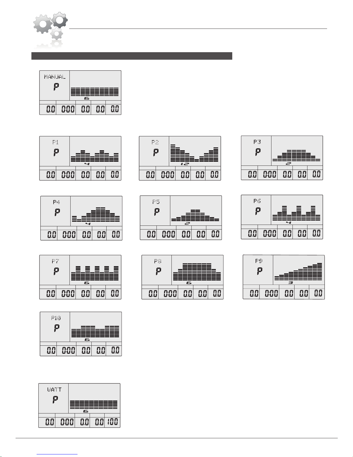
A: 1 Manual Program: (See fig 1)
B: 10 Preset Program Profiles: (See fig 2~fig 11)
DIST.
M
M/H
LEVEL
STOP
TIME CAL
WATT
fig 1
fig 2: P1 ROLLING
DIST.
M
M/H
LEVEL
STOP
TIME CAL
WATT
DIST.
M
M/H
LEVEL
STOP
TIME CAL
WATT
DIST.
M
M/H
LEVEL
STOP
TIME CAL
WATT
DIST.
M
M/H
LEVEL
STOP
TIME CAL
WATT
fig 3: P2 VALLEY fig 4: P3 FATBURN
DIST.
M
M/H
LEVEL
STOP
TIME CAL
WATT
fig 5: P4 RAMP fig 7: P6 INTERVAL
DIST.
M
M/H
LEVEL
STOP
TIME CAL
WATT
fig 6: P5 MOUNTAIN
C: 1 Watt Control Program: (See fig 12)
DIST.
M
M/H
LEVEL
STOP
TIME CAL
WATT
fig 8: P7 CARDIO
DIST.
M
M/H
LEVEL
STOP
TIME CAL
WATT
fig 9: P8 ENDURANCE
DIST.
M
M/H
LEVEL
STOP
TIME CAL
WATT
fig 10: P9 SLOPE
DIST.
M
M/H
LEVEL
STOP
TIME CAL
WATT
fig 11: P10 RALLY
DIST.
M
M/H
LEVEL
STOP
TIME CAL
WATT
fig 12
PROGRAMS (21 Total):
BRM8000/8800

Computer Operation
Page 13
D: 4 Heart Rate Control Programs: (See fig 13 ~ fig 16)
DIST.
M
M/H
LEVEL
STOP
TIME CAL
WATT
fig 14: 75% Heart Rate
DIST.
M
M/H
LEVEL
STOP
TIME CAL
WATT
fig 13: 55% Heart Rate
DIST.
M
M/H
LEVEL
STOP
TIME CAL
WATT
fig 15: 90% Heart Rate
DIST.
M
M/H
LEVEL
STOP
TIME CAL
WATT
fig 16: TARGET Heart Rate
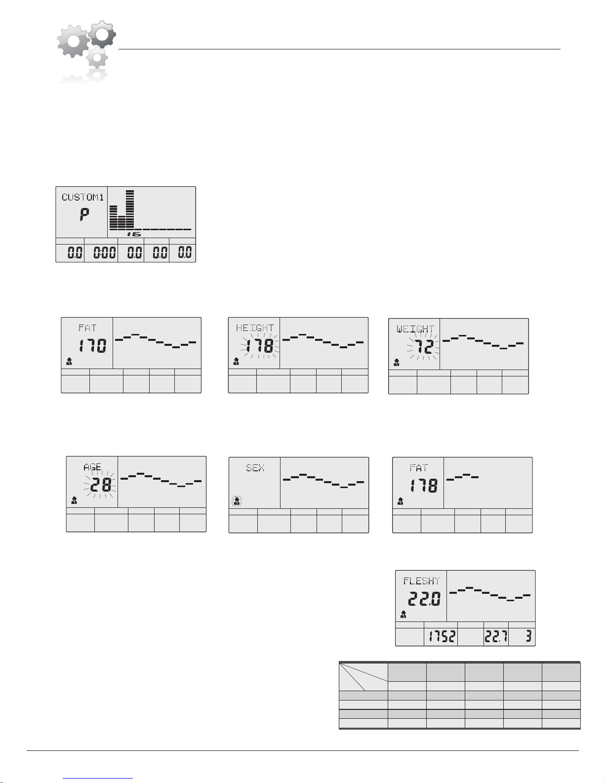
E: 4 User Setting Programs: CUSTOM1 to CUSTOM4 (See fig 17 ~ fig 20)
DIST.
M
M/H
LEVEL
STOP
TIME CAL
WATT
fig 17
DIST.
M
M/H
LEVEL
STOP
TIME CAL
WATT
fig 18
DIST.
M
M/H
LEVEL
STOP
TIME CAL
WATT
fig 19
DIST.
M
M/H
LEVEL
STOP
TIME CAL
WATT
fig 20
F: 1 Body Fat Measuring Program: (See fig 21)
STOP
cm
fig 21
2. You can record the user's data: GENDER, HEIGHT, WEIGHT and AGE.
3. The “dot matrix” display shows your current mode and/or status. (See fig 22 --as example of “CUSTOM4” program mode)
4. The simulative ECG graphic will show when your heart rate is being measured. (See fig 23)
5. The display will show: Speed (RPM), TIME, DIST., CAL., WATT, PULSE, LEVEL in the same window at the bottom of screen.
6. The computer will turn off automatically if there is QRWmotion or pulse detected for over 4 minutes. Meanwhile, it will store your current exercise
data and turn the resistance to the minimum. Once any button is pressed or motion is detected, the computer will turn on again automatically.
.
7. This computer features sleek “Finger-Touch” buttons
fig 23
fig 22
OTHER FEATURES:
BRM8000/8800

Computer Operation
Page 1
BRM8000
1.ENTER:
●When unit does not detect motion (STOP is displayed), press ENTER to enter into program selection and setting value which flash in related window.
A: After you select a program, press ENTER to confirm your selection.
B: When pre-setting values, press ENTER to confirm the value that you would like to preset.
●When unit detects motion (START is displayed), press ENTER to choose display of functions: SPEED, RPM, or automatic rotating.
●During any mode, hold down ENTER for 2 seconds to reset the computer.
2.START/STOP:
●Press START/STOP to start or stop the workout programs.
●During any mode, hold down START/STOP for 2 seconds to reset the computer.
3.UP:
●When unit is not in motion and dot matrix flashes, press UP to select the program up. If the related values flash, press UP to increase the value.
●During the start mode (START is displayed), press UP to increase the training resistance.
4.DOWN:
●When unit is not in motion and dot matrix flashes, press DOWN to select the program down. If the related values flash, press DOWN to decrease the value.
●During the start mode (START is displayed), press DOWN to decrease the training resistance.
5.RECOVERY3XOVH
●First, test your current heart rate and when your heart rate value displays, press RECOVERY to set the value and enter into pulse recovery testing.
●When you are in pulse recovery mode, press RECOVERY to exit the mode.
NOTE:
It is suggested your finger covers only the marked button region when pressing to avoid undesired button selection..
BUTTONS:
1.TURN ON THE COMPUTER
Plug in one end of the adaptor to the AC electrical source and connect the other end to the computer.
2.PROGRAM SELECTION & SETTING VALUES
●Manual Program and Preset Program P1 ~ P10
A.Press UP/DOWN button to select the program of your choice. (See fig 25)
B.Press ENTER to confirm the selected program and enter into the time-setting window..
C.The time will flash; then, press UP/DOWN to set your desired time. Press ENTER to confirm the time value. (See fig 26)
DIST.
M
RPMM/H
LEVEL
START STOP
PULSE
%
YEAR cm in Kg lb
TIME BMR CAL BMI
WATT BODY
fig 24
DIST.
M
M/H
LEVEL
STOP
TIME CAL
WATT
DIST.
M
M/H
LEVEL
STOP
TIME CAL
WATT
DIST.
M
M/H
LEVEL
STOP
TIME CAL
WATT
DIST.
M
M/H
LEVEL
STOP
TIME CAL
WATT
DIST.
M
LEVEL
START
TIME CAL
WATT
RPM
fig 25
OPERATION: (“HOW-TO”)
D.The distance will flash; then, press UP/DOWN to set the desired distance value. Press ENTER to confirm the distance value. (See fig 27)
E.The calories will flash; then, press UP/DOWN to set the desired calories to burn. Press ENTER to confirm the calories value. (See fig 28).
F.Press START/ STOP to begin the workout. (See fig 29)
fig 26 fig 27 fig 28 fig 29
The computer will beep and enter into initial mode.(See fig 24)

Computer Operation
Page 1
BRM8000
●WATT CONTROL PROGRAM
A.Press UP/DOWN to select the Watt Control Program.
B.Press ENTER to confirm the selected watt control program, and enter into time-setting window.
C.The time will flash; then, press UP/DOWN button to set up the desired time. Press ENTER to confirm the value.
D.The distance will flash; then press UP/DOWN to set up the desired distance value. Press ENTER to confirm the value.
E.The calories will flash; then press UP/DOWN to set up the desired calories to be consumed. Press ENTER to confirm the value.
F.The watt display will flash; then press UP/DOWN to set up the watt to do the exercise. Press ENTER to confirm the value. (See fig 30)
G.Press START/ STOP to begin exercise.
NOTE: The WATT value is decided by the TORQUE and RPM. In this program, the WATT value will keep at constant value. This means that if
you peddle quickly, the load resistance will decrease and if you peddle slowly, the load resistance will increase to ensure you are kept at
the same watt value.
HEART RATE CONTROL PROGRAM: 55%H.R, 75% H.R and 90% H.R
The maximum heart rate depends on different age and this program will ensure you do the healthy exercise within maximum heart rate.
A.Press UP/DOWN to choose the heart rate control program.
B.Press ENTER to confirm the heart rate control program, and enter into the time-setting window.
C.The time will flash; then, press UP/DOWN button to set up the desired time. Press ENTER to confirm the value.
D.The distance will flash; then, press UP/DOWN to set up the desired distance value. Press ENTER confirm the value.
E.The calories will flash; then, press UP/DOWN to set up the desired calories to be consumed. Press ENTER to confirm the value.
F.The age will flash; then, press UP/DOWN to set the user's age. Press ENTER to confirm the value. (See fig 31)
G.When the target heart rate control program flash, the computer will display the user's target heart rate according to user's age.
H.Press START/ STOP to begin exercise.
HEART RATE CONTROL PROGRAM: TARGET HEART RATE
The user can set any target heart rate for their exercise session.
A.Press UP/DOWN to select Target Heart Rate program.
. wodniwgnittesemitretnednaeciohcruoymrifnocotRETNEsserP.B
C.The time display will flash; then, press UP/DOWN to set the desired time to do the exercise. Press ENTER to confirm the value.
DIST.
M
M/H
LEVEL
STOP
TIME CAL
WATT
fig 30
DIST.
M
M/H
LEVEL
STOP
TIME CAL
WATT
YEAR
fig 31
●
●
D.The distance will flash; then, press UP/DOWN to set up the desired distance value. Press ENTER to confirm the value.
E.The calories will flash; then, press UP/DOWN to set up the desired calories to be consumed. Press ENTER to confirm the value.
F.The target heart rate will flash; then, press UP/DOWN to set up your target heart rate. Press ENTER to confirm the value. (See fig 32)
G.Press START/ STOP to begin exercise.
NOTE: During exercise, the user's heart rate value depends on resistance level and speed. The heart rate control program is to ensure your heart
rate within the preset value. When the computer detects your current heart rate is higher than preset, it will decrease the resistance level automatically
or you may slow down exercise. If your current heart rate is lower than preset, it will increase resistance and you may speed up.
DIST.
M
M/H
LEVEL
STOP
TIME CAL
WATT
fig 32
Computer Operation
Page 1
BRM8000
DIST.
M
M/H
LEVEL
STOP
TIME CAL
WATT
fig 33
●USER PROFILE PROGRAMS: CUSTOM1~ CUSTOM4
A.Press UP/DOWN to select the desired user profile (up to 4 available).
. .wodniwgnittes-emitehtotniretnedna,eciohcruoymrifnocotRETNEsserP.B
C.The time display will flash; then, press UP/DOWN to set up the desired time to do the exercise. Press ENTER to confirm the value.
D.The distance will flash; then, press UP/DOWN to set up the desired distance value. Press ENTER to confirm the value.
E.The calories will flash; then, press UP/DOWN to set up the desired calories to be consumed. Press ENTER to confirm the value.
F.The first resistance level will flash; then, press UP/DOWN to set the desired load resistance. Press ENTER to confirm. Then repeat above operations
to set the resistance from 2 to 10. (See fig 33)
G.Press START/ STOP to begin exercise.
●BODY FAT MEASUREMENT PROGRAM
A.Press UP/DOWN to select the BODY FAT TEST program. (See fig 34)
B.Press ENTER to confirm your choice, and enter into height-setting mode.
STOP
cm
fig 34
STOP
cm
fig 35
C.The height display will flash; then, press UP/DOWN to set up your height. Press ENTER to confirm the value. (See fig 35)
D.The weight display will flash; then, press UP/DOWN to set up your weight. Press ENTER to confirm the value.(See fig 36)
E.The age display will flash; then, press UP/DOWN to set up your age. Press ENTER to confirm the value. (See fig 37)
F.The gender display will flash; then, press UP/DOWN to set up your gender. Press ENTER to confirm. (See fig 38)
STOP
Kg
fig 36
STOP
YEAR
fig 37
STOP
fig 38
G.Press START/STOP to begin testing your body fat.(See fig 39)
START
cm
fig 39
NOTES:
① During the body fat measurement, place both your palms on the pulse sensor pads.
The test results shown are: FAT%, BMR (Basal Metabolic Rate),
BMI (Body Mass Index), BODY and body shape. (See fig 40)
FAT%: The total body fat in our body measured by percentage
BMR : Basal Metabolic Rate (metabolism) is the energy (measured in
calories) expended by the body at rest to maintain normal bodily function.
BMI: “Body Mass Index” is a measurement often used for strength training.
②If you see the “ERROR2” message, it is because the computer is unable to
detect your pulse. Please ensure your hands are placed firmly but not tightly
on the sensors. Press START/STOP to try again.
.
③During the test calculations, you cannot exit. After results are shown, press
UP/DOWN to exit the body fat measurement program and switch to another.
④*The table to the right is for reference only and is not intended to provide any
medical advice. Please see your physician or medical advisor for any health or
bodily-related questions or concerns.
Slim Healthy Fleshy
Over weight Obese
5YDOB4YDOB3YDOB2YDOB1YDOB
%53>%53~%1.52%52~%1.02%02~%41%41<
%83>%83~%1.82%82~%1.32%32~%71%71<
Female/≤30 years old %04>%04~%1.03%03~%1.42%42~%71%71<
%34>%34~%1.33%33~%1.72%72~%02%02<
Body Shape
FAT%
Age/
Gender
Male/≤30 years old
Male/>30 years old
Female/>30 years old
STOP
BMR BMI
BODY
fig 40
%
Reference Table*
Computer Operation
Page 17
BRM8000/8800
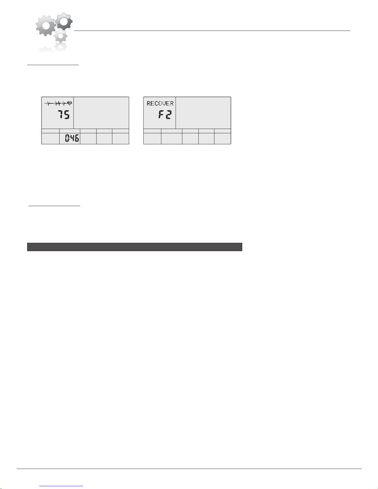
The pulse recovery test is to compare your heart rate before and after exercise. It is target to determine your heart strength via the measuring.
Please follow the procedure below for the Pulse Recovery Test:
A.Place both your hands firmly but not too tightly on the pulse sensor pads until your current pulse value shows on the screen.
B.Press RECOVERY to enter the pulse recovery test and the computer program will enter a paused status. (See fig 41)
C.Continue allowing the pulse sensor pads to detect your pulse..
D.You will see “TIME” begin countdown from 60 seconds to 0 second. Keep your hands rested on the pulse sensor pads.
E.When time reaches 0, the test result (F1-F6) will appear. The result meanings are as follows:.
F1=Excellent , F2=Good , F3=Fair , F4=below average , F5= No Good , F6= Poor (See fig 42)
F.If the computer does not detect your current heart rate first, pressing RECOVERY will not start the Pulse Recovery Test. Please see the
Troubleshooting on Page 18. You may press RECOVERY if you choose to exit the test.
Place both your palms on the pulse sensor pads and the computer will show your current heart beat rate in beats per minute (BPM) on the LCD
after 3~4 seconds. During the measurement, a heart icon will flash with simulative ECG showing.
NOTE:
STOP
PULSE
TIME
fig 41 fig 42
STOP
3. PULSE RECOVERY TEST
4. PULSE MEASUREMENT
①During pulse measurement, sometimes the value needs to stabilize. Do not release your hands until a stabilized measurement is shown.
The measurement value cannot be regarded as the basis of medical treatment.
②
SPECIFICATIONS
Speed (MPH): Shows your current speed. Range: 0.0~99.9 Miles Per Hour.
RPM: ~999.
TIME: Shows accumulated exercise time, range : 0:00~99 minutes 59 seconds.
The preset time range is 5:00~99 minutes. The computer will start to countdown from the preset time until it reaches 0:00
When it reaches zero, the program will stop and computer alarm will beep. If no time is preset, the computer will run for one
minute at each resistance level.
DIST: Shows exercise accumulated distance. Range : 0.0~99.9~999M
PULSE: Shows the user’s heart rate value. Range: 30 ~ 240 BPM (beats per minute)
*Please be aware that the pulse sensors are not medical devices; the pulse sensors should not be used or
applied for medical reasons.
RESISTANCE LEVEL: Shows the resistance level. Range: 1 ~ 16
WATT: Shows the wattage output of user during exercise.
■ERROR MESSAGES
1. When the computer displays ERROR1, please check if the motor is functioning correctly and if the motor wires are fully connected.
2. When the computer displays ERROR2, this means there is no body signal detected; please check if your hands are properly in contact with
the pulse sensor pads.
3. Please also refer to Troubleshooting on Page 18 for additional troubleshooting assistance.
■AUDIO AMPLIFIER AND SPEAKER
Connect the audio input plug to your audio player device, and the other end into the corresponding hole on the computer. Then, turn on the audio
switch on the right side of the computer.
■ADAPTOR
INPUT: AC (Voltage varies; please see Adaptor label for more details)
OUTPUT: 8VDC 500mA or 9VDC 800mA (for MP3)
Shows the current rotation per minute. Range : 0
When the distance reaches zero, the program will stop and computer alarm will beep.
CALORIE: Shows accumulated calories burnt. Range: 0.0 ~ 99.9 ~ 999
The preset calorie range is 10.0 ~ 90.0 ~ 990. When the calories reach zero, the program will stop and computer alarm will beep.

Troubleshooting
If the computer is not picking up your hand pulse signal (or you are getting
inaccurate readings), please adjust the following:
1. Slightly moisten/dampen the palms with water so the sensors can detect a
pulse signal.
2. Do not grip the sensors too tightly. Only moderate pressure need be applied.
Gripping the sensors too tightly restricts and seizes detection of your pulse.
3. Remove any rings or jewelry to prevent interference.
4. Check to ensure all pulse sensor wires are properly connected and are
not damaged.
You may need to refer to installation/assembly directions for the pulse sensor
wires in this manual.
If the computer is not displaying the CALORIES/DISTANCE/TIME/(ETC.) functions
(or you are getting inaccurate readings), please adjust the following:
1. Check to ensure all computer sensor wires are properly connected and are
not damaged.
You may need to refer to installation/assembly directions for the sensor wires
in this manual.
If the computer display is blank & not displaying any data (or does not appear to
power on), please adjust the following:
1. Check to ensure all sensor wires are all properly connected and are
not damaged.
2. Check to ensure the AC Adapter* or Batteries* are properly plugged in or
fully charged.
Troubleshoot Area
HAND PULSE SIGNAL
CALORIES/DISTANCE/
TIME/(ETC.)
COMPUTER Display
(AFTER COMPLETE ASSEMBLY)
Solution
*Please check your product manual to determine if your model uses either
1. an AC Adapter, or 2. Batteries to power your unit.
For your safety, please do not discard this Troubleshooting sheet or the Owner’s Manual,
and keep them in a place where you can easily access/refer to them at any time.
If you are still having any troubleshooting issues, please contact our Customer Support
for further assistance.
Page 1
BRM8000/8800
This manual suits for next models
1
Table of contents
Other Body flex Exercise Bike manuals


