Body Go YK-R1901 User manual

`
USER MANUAL
IMPORTANT!
Please retain owner’s manual for maintenance and adjustment instructions.

2
IMPORTANT SAFETY INFORMATION
We thank you for choosing our product. To ensure your safety and health, please use this
equipment correctly. It is important to read this entire manual before assembling and using the
equipment. Safe and effective use can only be achieved if the equipment is assembled,
maintained and used properly. It is your responsibility to ensure that all users of the equipment
are informed of all warnings and precautions.
1. Before starting any exercise program, you should consult your physician to determine if you
have any medical or physical conditions that could put your health and safety at risk, or
prevent you from using the equipment properly. Your physician’s advice is essential if you are
taking medication that affects your heart rate, blood pressure or cholesterol level.
2. Be aware of your body’s signals. Incorrect or excessive exercise can damage your health.
Stop exercising if you experience any of the following symptoms: pain, tightness in your chest,
irregular heartbeat, shortness of breath, lightheadedness, dizziness or feelings of nausea. If
you do experience any of these conditions, you should consult your physician before
continuing with your exercise program.
3. Keep children and pets away from the equipment. The equipment is designed for adult use
only.
4. Use the equipment on a solid, flat level surface with a protective cover for your floor or carpet.
To ensure safety, the equipment should have at least 2 feet (60 CM) of free space all around
it.
5. Ensure that all nuts and bolts are securely tightened before using the equipment. The safety
of the equipment can only be maintained if it is regularly examined for damage and/or wear
and tear.
6. Always use the equipment as indicated. If you find any defective components while
assembling or checking the equipment, or if you hear any unusual noises coming from the
equipment during exercise, discontinue use of the equipment immediately and do not use
until the problem has been rectified.
7. Wear suitable clothing while using the equipment. Avoid wearing loose clothing that may
become entangled in the equipment.
8. Do not place fingers or objects into the moving parts of the equipment.
9. The maximum weight capacity of this unit is 120 KG.
10. The equipment is not suitable for therapeutic use.
11. To avoid bodily injury and/or damage to the product or property, proper lifting and moving is
required.
12. Your product is intended for use in cool, dry conditions. You should avoid storage in extreme
cold, hot or damp areas as this may lead to corrosion and other related problems.
13. This equipment is designed for indoor and home use only, it is not intended for commercial
use!

3
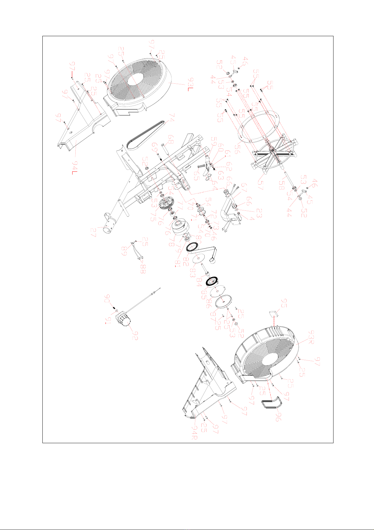
EXPLODED DIAGRAM
4
5
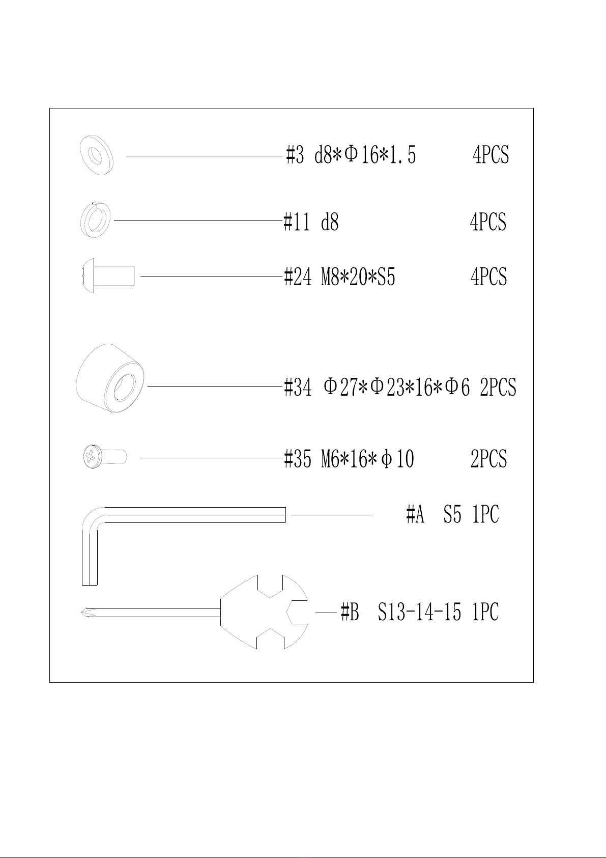
Hardware:

6
Parts List
No. Description Qty No. Description Qty
1 Bolt M8*42*15*S6 2 33
Rail 1
2 Transportation Wheel 2 34
Limiter 4
3 Washer d8*Φ16*1.5 16 35
Bolt M6*16*φ10 4
4 Nylon nut M8*H7.5*S13 6 36
Rail upper cover 1
5 End cap Φ60.5*17 4 37
Rail lower cover 1
6 Front bottom tube 1 38
Rear supporter 1
7 Nut M8 4 39
Bolt M8*16*S14 4
8 Adjustable foot pad φ52*18 4 40
Seat 1
9 Bolt M8*73*20*H5 2 41
U baffle plate 2
10 Arc washer d8*Φ20*2*R30 8 42
Left support plate of seat 2
11 Spring washer d8 12 43
Bolt M8*135*15*S14 3
12 Cap nut M8 2 44
Chain bolt M6*40*Φ10*2.5 4
13 Bolt M5*10 4 45
Chain U seat 4
14 End cap 1 46
Nylon nut M6*H6*S10 5
15 Computer 1 47
Spacer d8*Φ15*4 6
16 Trunk wire 2 48
Bearing 608Z 10
17 Handlebar holder 1 49
Roller Φ45*38*Φ22 4
18 Bolt M5×10×Ф8.5 2 50
Spacer Φ14*Φ8.3*30 2
19 Foam grip 2 51
Roller Φ33*106*Φ22 1
20 End cap Φ32*17 2 52
Nut M10*1*H9.5*S15 4
21 Handlebar 1 53
Nut M10*1*H5*S17 4
22 Bolt M8*20*S13 4 54
Bearing 6000-2RS 5
23 Washer d8*Φ20*2 5 55
Screw ST4.2*13*φ716
24 Bolt M8*20*S5*φ13 11 56
Aluminium sheet 4
25 Screw ST4.2*16*Φ818 57 Fan 1
26L/R Cover 1pair 58 Flywheel shaft 1
27 Main frame 159 Magnetic plate 1
28 Pedal strap 260 Wave washer d12*Φ15.5*0.3 1
29 Pedal 261 Washer d6*Φ16*1.5 1
30 Pedal plate 1 62
Spring washer d6 1
31 Bolt M5*10 4 63
Bolt M6*12*S10 1
32 Rail piece 2 64
Magnet Φ24*5 2
65 Spring Φ1.2*Φ15*48*N9 84
Axle for Mesh Belt Wheel 1

7
66 Bushing Φ32*3.3*Φ28*16*Φ14 285 Volute Spring 1
67 Computer post 186 Outer PC Board 1
68 Knob Φ14*81.5*M8*S6 1 87
Outer Cover for Mesh Belt Wheel 1
69 Bolt M6*55*15*S10 1 88
Sensor 2
70 Washer d10 2 89
Sensor holder 1
71 Pulley Φ45*35 1 90 Bolt M5*20 1
72 Fixing Axle for Mesh Belt 1 91 Washer d5*Φ16*1.5 1
73 Wave washer d10 1 92 Tension knob 1
74 Belt 1 93L/R Front cover 1pair
75 Belt plate 1 94L/R Rear cover 1pair
76 Bearing 16003-2RS 2 95
Support pad of Housing 1
77 Bearing ф35*d17*16 1 96
Rubber ring 1
78 Mesh Belt Wheel 1 97
Screw ST4.2*16*φ812
79 Washer d35 1 A
Spanner S5 1
80 Fixing Axle for Mesh Belt 1 B
Wrench S13-14-15 1
81 Bearing 6300-2RS 1
82 Mesh Belt 1
83 PC Board for Mesh Belt Wheel 1
8
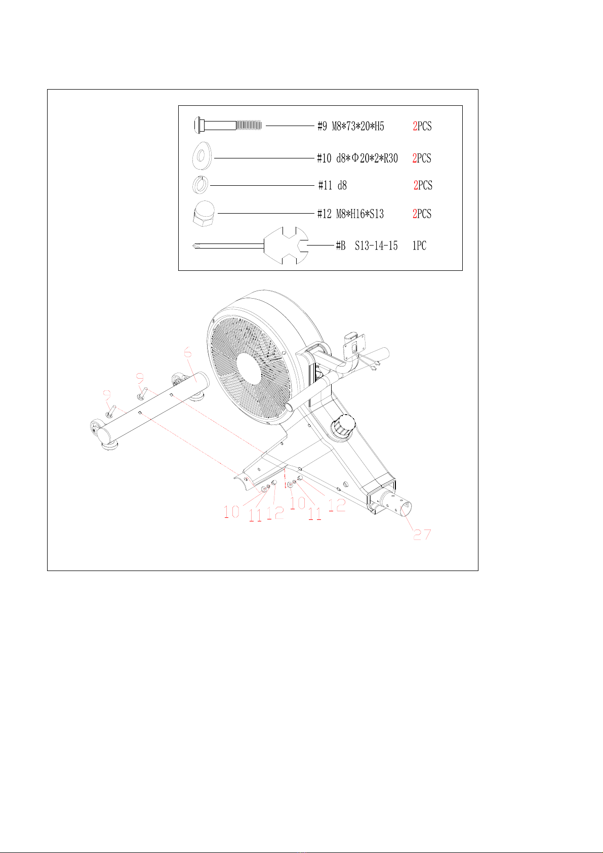
Step 1:
Take out the bolts(9), arc washers(10), spring washers(11) and cap nuts(12)
from main frame(27) by wrench(B), then attach front bottom tube(6) to main
frame(27) with bolts(9), arc washers(10), spring washers(11) and cap nuts(12)
by wrench(B).
9
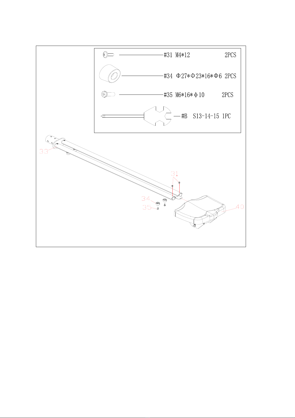
Step 2:
a. Take out bolts(31) from rail(33) by wrench(B);
b. Insert seat(40) into rail(33);
c. Secure rail piece(32) in the rail(33) with bolt(31) by wrench(B);
d. Secure limiter(34) in the rail(33) with bolts(35) by wrench(B).

10
Step 3:
36
37
25
311
24
3
11
24
24
11
3
33
38
a. Secure rail upper and lower cover(36&37) on the rail(33) with screws(25) by
wrench(B);
b. Secure rear supporter(38) on the bottom of rail(33) with washers(3), spring
washers(11) and bolts(24) by spanner(A).

11
Step 4:
a. Take out arc washers(10), spring washers(11) and bolts(24) from main frame(27)
by spanner(A);Take out screws(25) from main frame(27) and cover(26L/R) by
wrench(B);
b. Attach rail(33) into main frame(27), then secure them with arc washers(10),
spring washers(11) and bolts(24) by spanner(A);
c. Secure cover(26L/R) on the main frame(27) with screws(25) by wrench(B).
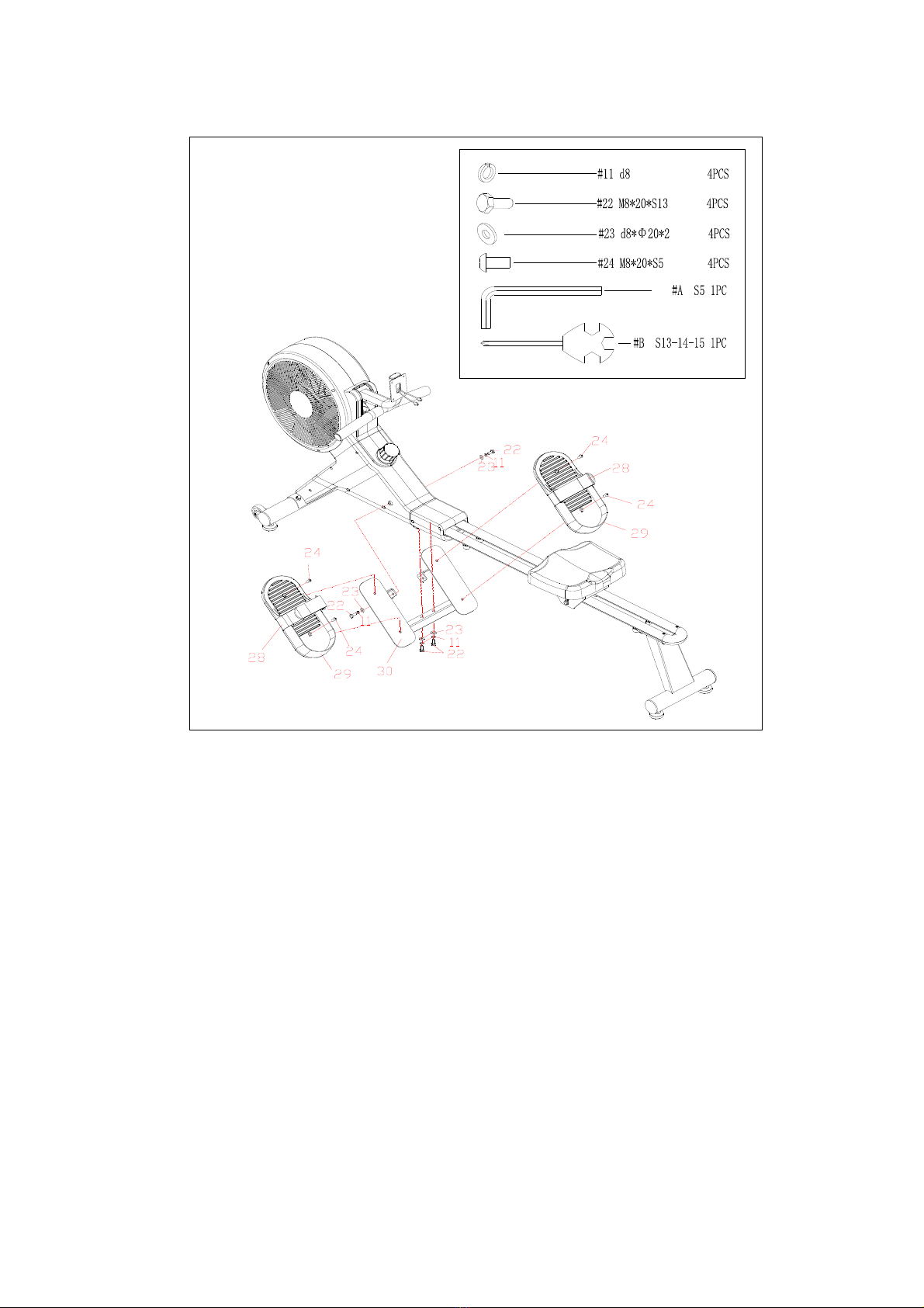
12
Step 5:
a. Take out spring washers(11), bolts(22) and washers(23) from main frame(27) by
wrench(B);
b. Secure pedal plate(30) to main frame(27) with spring washers(11), bolts(22) and
washers(23) by wrench(B);
c. Secure pedal(29) in the pedal plate(30) with bolts(24) by spanner(A);
Attention: The pedal strap(28) should be put in the long groove which is at the
bottom of pedal(29), and the pedal(29) must not press the pedal strap(28), so that
the pedal strap(29) could be free to pull up and down.
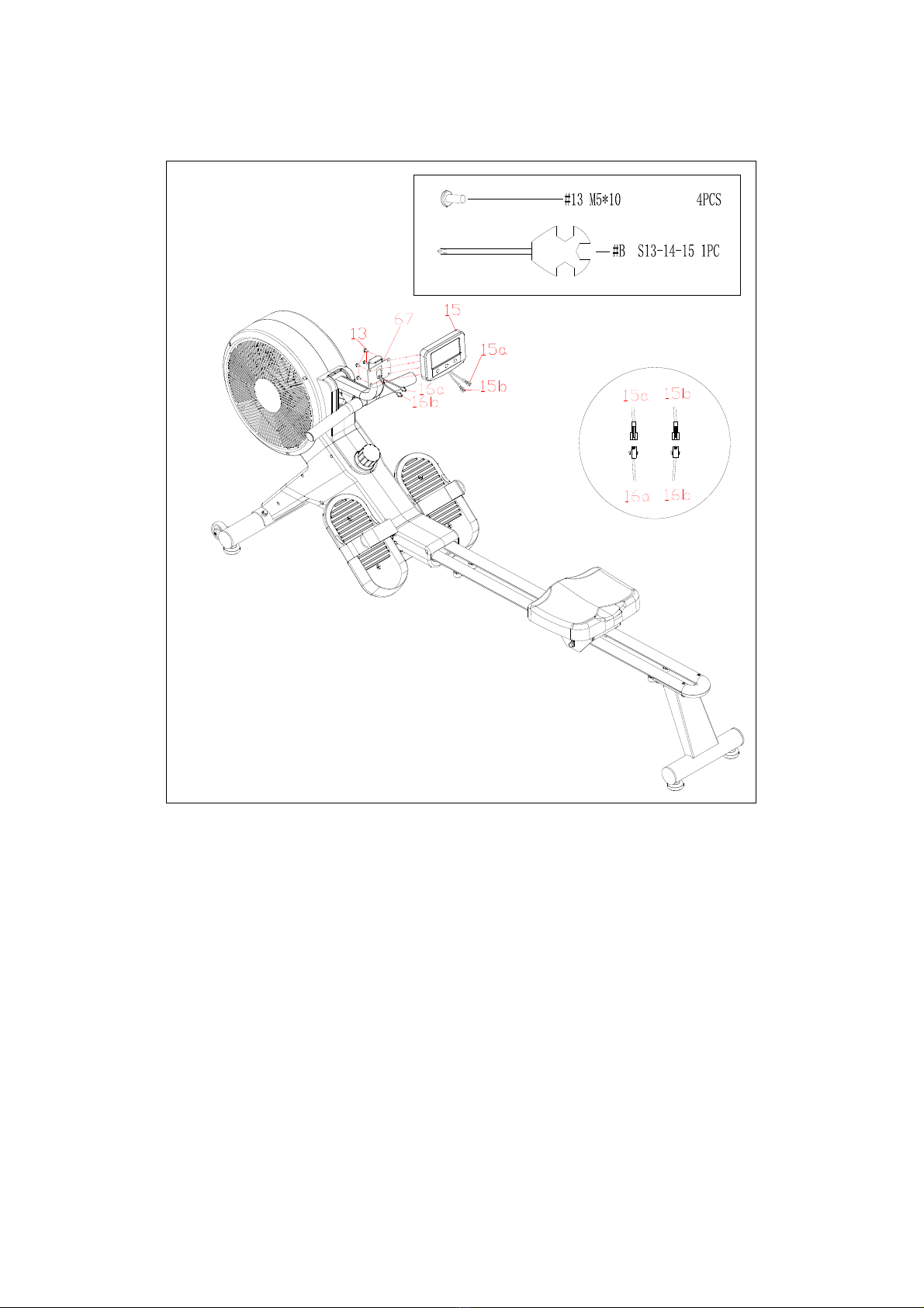
13
Step 6:
a. Pull out the trunk wire(16a/16b) from computer post(67), then connect them with
computer wires(15a/15b), then put these wires into the computer post(67) by
return;
b. Secure computer(15) on the computer post(67) with bolts(15) by wrench(B) ;
14
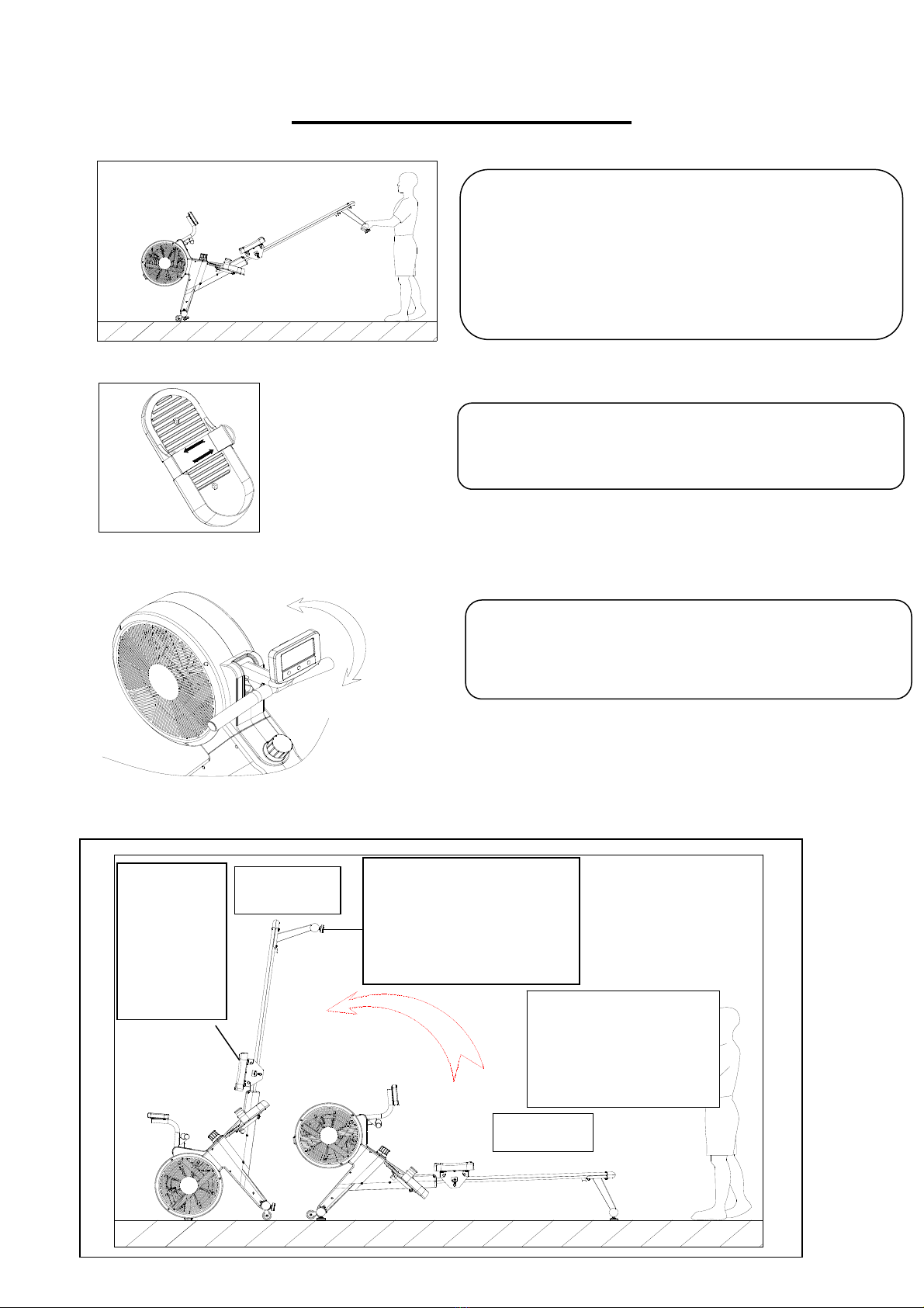
ADJUSTMENTS GUIDE
1.MOVING THE MACHINE
2.PEDAL ADJUSTMENT
3.COMPUTER ANGLE ADJUSTMENT
4.Storage
图A
图B
To move the machine, lift up the Rear supporter
(38) until the transportation wheels on the Front
bottom tube(6) touch the ground. With the
wheels on the ground, you can transport the bike
to the desired location with ease.
The pedal strap is adjustable and can be
personalized to fit the user’s foot size.
The rotation angle of computer post can be
adjusted to obtain the best view of the Computer
LCD screen.
Attention!
The seat will
slip when
the machine
be stand up.
Figure A Attention!
The head of user is easy to
collide when the machine be
stand up.
When not in use, you
can stand up the
machine to save the
space .
Figure B

15
YK-R1901 EXERCISE MONITOR INSTRUCTION
DISPLAY INFORMATION FUNCTION DESCRIPTION
1. In the main display area with motion status:
a) Scan mode: Display change according to the next items every 6 seconds,
TIME-> TIME/500m ->DISTANCE->PULSE(Optional) ->CALORIE->SPM ->STROKES->TOTAL STROKES;
b) Press “MODE” key lets you to select and lock on to a particular function you want;
2. TIME (TIME/500m), DISTANCE, PULSE(Optional), CALORIE, SPM,STROKES (TOTAL STROKES) display area;
KEY FUNCTION
INSTRUCTION:
1. Motion status:
a. Scan mode: Icon flashing display;
b. Press “SET” key to change display TIME /TIME 500m and STOKES/TOTAL STROKES;
c. Press “MODE” key to select and lock on to a particular function;
d. Please wear a wireless heart rate chest strap, when you need a heart rate reading;
2.Stop Status:
1) SET key: enter the setting mode , and adjusted the value of choose set items;
2) MODE key: to choose setting items with relevant flashing for TIME ->DISTANCE->PULSE(Optional) ->CALORIE
->STROKES;
1) If the pulse limit is setting , when the heart rate exceeds the set limit, the beep will continuously prompt(Optional);
2) If TIME/DISTANCE/CALORIE/STROKES is setting,The corresponding value will be inverted in motion status。When
any of setting value count to 0, the motion will be “DI DI” Voice Prompt;
SPECIFICATION
TIME. 0M:00S ~ 99M:59S STROKES 0 ~ 9999
TIEM/500m 0M:00S ~ 99M:59S TOTAL STROKES 0 ~ 99999
DISTANCE 0.0 ~ 9999KM Batter
y
T
yp
e Size-AAA *2
PULSE
(
O
p
tional
)
40-240BPM O
p
eratin
g
Tem
p
erature 0℃~+40℃
CALORIES 0.0~ 9999KCAL Stora
g
e Tem
p
erature -10℃~+60℃
SPM 0.0 ~ 999RPM
TIME The time of each workout ,when startin
g
exercise.
TIEM/500m Avera
g
e time
p
er 500 meters.
DISTANCE The distances of each workout ,when startin
g
exercise.
PULSE
(
O
p
tional
)
Heart beat .
CALORIE The calorie burned of each workout, when startin
g
exercise.
SPM STROKES/MINUTE.
STROKES The strokes of each workout, when starin
g
exercise.
TOTAL STROKES The total strokes of all workout, from battery capacity period runs.
MODE . In motion status: select and lock on to a particular function;
. In stop status: and choose set items needs to be set
SET . In motion status : display change TIME or TIME 500m, STROKES or TOTAL STROKES;
. In stop status: enter the setting mode , and adjusted the value of choose set items;
RESET . In setting mode: the value clear;
. In stop status: all of the values with items will be clear, except TOTAL STROKES;

16
Table of contents
Other Body Go Exercise Bike manuals


