body Power BR2710 User manual

BR2710
OWNER’S MANUAL
* This item is for consumer use only and it is not meant for commercial use.
OWNER’S MANUAL
* This item is for consumer use only and it is not meant for commercial use.

This page intentionally left blank

General Information
BR 2710 Page 1
Warranty
Body Flex Sports warrants your product for
a period of 1 year for the frame and 90 days
on all parts if the item is used for the intended
purpose, properly maintained and not used
commercially. Any alterations or incorrect
assembly of the product will void this warranty.
Proof of purchase must be presented for any
warranty validation (no exceptions). This
warranty applies to the original purchaser only
and is not transferable.
This warranty does not cover abuse or defects
caused during use, storage or assembly.
During the warranty period, Body Flex Sports
reserves the right to:
a). provide replacement parts to the
purchaser in an effort to repair the item.
b). repair the product returned to our
warehouse (at the purchaser’s cost).
c). replace the product if neither of the two
previously mentioned actions effect repair.
This warranty does not cover normal wear and
tear on upholstery.
Questions
If you have any questions concerning the
assembly of your item or if any parts are
missing, please DO NOT RETURN THE
ITEM TO THE STORE OR CONTACT THE
RETAILER. Our dedicated customer service
staff can help you with any questions you may
have regarding the assembly of this unit and
can also mail you replacement parts.
Customer Support
Customer Support is open 9:00 a.m. to 5:00
p.m. (Pacific Time) Monday through Friday.
Please contact us by any of the following
means.
Body Flex Sports, Inc.
21717 Ferrero Parkway, Walnut, CA 91789
Telephone: (888) 266 - 6789
Fax: (909) 598 - 6707
Email: info@bodyflexsports.com
Safety
Before you undertake any exercise program,
please be sure to consult with your doctor.
Frequent strenuous exercise should be
approved by your doctor and proper use
of your product is essential. Excessive or incorrect
training may result to health injuries. Please read
this manual carefully before commencing the
assembly of your product or starting to exercise.
• Please keep all children away from this item
when in use. Do not allow children to climb or
play on them when they are not in use.
• Supervise teenagers while they use this unit.
• For your own safety, always ensure that there
is at least 3 feet of free space in all directions
around your product while you are exercising.
• Regularly check to see that all nuts, bolts and
fittings are securely tightened. Periodically
check all moving parts for obvious signs of
wear or damage.
• Clean only with a damp cloth, do not use
solvent cleaners. If you are in any doubt, do
not use your product; contact CUSTOMER
SUPPORT.
• Before use, always ensure that your product
is positioned on a solid, flat surface. If
necessary, use a rubber mat underneath to
reduce the possibility of slipping.
• Always wear appropriate clothing and
footwear such as training shoes when
exercising. Do not wear loose clothing that
could become caught in moving parts during
exercise.
• Do not use this unit if it is not functioning
properly or if it is not fully assembled.
• Do not use this unit for commercial purposes.
This unit is for home use only.
Storage and Use
Your product is intended for use in clean
dry conditions. You should avoid storage in
excessively cold or damp places as this may
lead to corrosion and other related problems.
Weight Limit
Your product is suitable for users weighing:
300 pounds or less.
• Before use, you must read and understand all
instructions & warnings stated in this Owner’s
Manual as well as posted on the equipment.
• It is the facility owner’s responsibility to properly
instruct users on the proper operation of the
equipment and to warn them of the potential
hazards.
• If at any time during exercise you feel faint, dizzy
or experience pain, stop and consult your
physician.
Assembling Tools
- Ruler with both metric and English measurements
- 2 x Adjustable Wrenches
- 1 x Philips (”Crosshead”) Screw Driver
•
Any adjustment devices that could interfere with
the user's movement on this unit should not be
left projecting.

Page 2
pre-assembled
12
#60
pre-assembled
59. Special Washer
pre-assembled
Hardware List
The following hardware is used to assemble your unit. Please take a moment to familiarize yourself with these items.
PLEASE NOTE: some of these parts may have already been pre-assembled on your unit.
BR 2710
pre-assembled

Page 3
BRM 3670 Stride Cycle Page ?
# Description # Description
1 Main Frame 29L/29R Left/Right Lower Handlebar
2 Rear Stabilizer 30 Bolt (M8x15 mm)
3 Adjustable End Cap 31 Front Post
4 Carriage Bolt (M8x73 mm) 32L-1/32L-2 End Cap
5 Arc Washer (M8 R30.5) 33 Spacer (φ32xφ19.2x67mm)
6 Cap Nut (M8) 34 Computer
7 Front Stabilizer 35 Arc Washer (M8 R16)
8 End Cap 36 Carriage Bolt (M8x40 mm)
9 Screw (M3x15 mm) 37 Big Washer (M8)
10L-1/10L-2 End Cap 38 Spring Washer (M8)
11L/11R Left/Right Pedal Arm 39 Hex Bolt (M8x15 mm)
12 Bushing (φ28xφ19x24.5) 40R-1/40R-2 End Cap
13 Big Washer (M10) 41 Screw (M4x8 mm)
14 Nylon Nut (M10) 42 Washer (M5)
15 Plastic Spacer (φ31.8xφ19.2x36) 44 Water Bottle Holder
16 Nylon Nut (M8) 45 Water Bottle
17 Washer (M8) 46L/46R Left/Right Upper Handlebar
18L/18R Left/Right Pedal 47 Foam of Upper Handlebar
19 Hex Bolt (M8x45 mm) 48 End Cap
20 Screw (M4x20 mm) 49 Steel Plate of Handle Pulse
21L-L/21L-R End Cap 50 Foam of Middle Handlebar
22 Hex Bolt (M8x75 mm) 51 Washer (M6)
23 End Cap 52a/52b Handle Pulse Wires
24a Sensor Wire (Lower) 53 Middle Handlebar
24b Sensor Wire (Middle) 54 Cover of Handlebar
24c Sensor Wire (Upper) 55 Bolt (M8x30 mm)
25 Bushing (φ28xφ14x24) 56 Screw (M4x19 mm)
26 Spacer (φ14xφ8x59) 57 End Cap
27R-1/27R-2 End Cap 58 AC Adapter
28R-L/28R-R End Cap 59 Special Washer
60 Screw (M4x12 mm)
BR 2710
Parts Listing
The following parts list describes all of the parts illustrated on the
exploded diagram on the following page. Please note, most of
these parts are already pre-assembled on your unit.

Page 4 BR 2710
The following diagram is provided to help you familiarize yourself with the parts and
hardware that will be used during the assembly process. Please note that not all of the
parts and hardware you see here will be used while you are assembling the machine
because some of these items are already pre-installed. Please continue to the next
page to begin the assembly process and use this page only as a reference guide for
parts and hardware.
Exploded Diagram

Page 5
Assembly Instructions
Hardware RequiredAssembly Step 1
Stabilizer Assembly
Secure the Front Stabilizer (#7)and Rear
Stabilizer (#2)to the Main Frame (#1) by
using four Carriage Bolts (#4), four Arc
Washers (#5) and four Cap Nuts (#6)
BR 2710

Page 6
Assembly Instructions
Assembly Step 2 Hardware Required
Front Post Assembly:
A.With the help of an assistant, connect the
Sensor Wire (Lower) (#24a) to the Sensor
Wire (Middle) (#24b).
B.Secure the Front Post (#31)to the Main
Frame (#1) by using four Bolts (#30)and
four Washers (#17).
BR 2710

Page 7
Assembly Instructions
Hardware Required
#59. Special Washer
[4 peices]
Assembly Step 3
Lower Handlebar Assembly:
The two Spacers (#33) and Special Washers (#59) are
already pre-assembled on the two bars that are protruding
from the Front Post (#31).Ensure that they are properly
in place as indicated in the assembly below.Slide the Left
Lower Handlebars (#29L)
with the longer end of the shaft
towards the center of the Front Post (#31). Then secure it
with one Big Washer (#37), aSpring Washer (#38) and
aHex Bolt (#39). Repeat this process on the other side.
Pedal Arm Assembly:
The Plastic Spacer(#15) and the Special Washer (#59)
are already pre-assembled.Ensure that they are properly
in place as indicated in the assembly below.Slide the Left
Pedal Arm (#11L) into the Crank Stud and secure it with
one Big Washer (#13) and a Nylon Nut (#14) as shown
in the assembly below.Repeat this process on the
opposite side.
Before attaching the Left Lower Handlebar (#29L) to the
Left Pedal Arm (#11L),
remove the zip tie at the bottom of
the Left Lower Handlebar (#29). Then attach the Left
Lower Handlebar (#29) to the Left Pedal Arm (#11) and
secure it with a Hex Bolt (#22), a Washer (#17) and a
Nylon Nut (#16).
Repeat this process on the opposite side.
BR 2710

Page 8
Assembly Instructions
Assembly Step 4Hardware Required
Upper Handlebar Assembly :
Attach the Upper Handlebars (#46L & #46R)
to the Lower Handlebars (#29L & #29R)and
secure them with four Carriage Bolts (#36),
four Arc Washers (#35)and four Cap Nuts
(#6).
Attach the snap-on End Cap (#32L-1, 32L-2)
to the left Left Lower Handlebar (#29L).Align
the two together and press firmly until it snaps
into place.
Repeat this process on the opposite side.
BR 2710

Page 9
Assembly Instructions
A s s e m b l y S t e p 5 Hardware Required
Middle Handlebar Assembly :
Attach the Middle Handlebar (#53) onto the front side of the
Front Post (#31),then secure it by using two Spring Washers
(#38) and two Bolts (#55).
Feed the Handle Pulse Wire (#52a) through the neck of the
Front Post (#31) until is sticking out of the opening. You will
need to connect the wire to the Computer (#34) later. Slide the
Cover of Handlebar (#54) to the Middle Handlebar (#53) as
illustrated.
Computer Assembly:
Remove the Screws (#60) that are pre-assembled on the
Computer
(#34) and set them aside as they will be used in a
later process.
Connect the Sensor Wire (middle) (#24b) to the Sensor wire
(upper) (#24c). Then connect the Handle Pulse Wire (#52a)
to the Handle Pulse Wire (#52b). Attach the Computer (#34)
to the bracket on the Front Post (#31) by using four Screws
(#60) that were previously removed.
After complete assembly: If the computer
is not picking up your hand pulse signal
(or you are getting inaccurate readings),
Please refer to our “Troubleshooting”
section on Page 18 for other troubleshoot
issues.
HAND PULSE SIGNAL
Troubleshooting
#60.Screw (M4x12 mm)
[4 Pieces]
Feed the Pulse
Sensor Wires(#52a)
through the neck
of the Front Post
(#31) until they are
sticking out of the
opening.
BR 2710

Page 10
Assembly Instructions
Assembly Step 6Hardware Required
Pedal Assembly:
Attach the Pedals (#18L & #18R)to Pedal Arm
(#11L & #11R)then secure with four Hex Bolts
(#19), four Washers (#17) and four Nylon Nuts
(#16). Align the pedals to the standard position
as shown. To better fit the way you exercise you
can customize the pedal to any of the 3 available
positions that gives you most comfortable distance
to grip the handlebars.
Assemble the End Caps (#10L-1 & #10L-2)
to the rear of the Left Pedal Arm (#11L) with
three Screws (#9). Repeat this process on
the opposite side.
Assemble the End Caps (#21L-L& #21L-R)
to the front of the Left Pedal Arm (#11L) with
two Screws (#20). Repeat this process on the
opposite side.
BR 2710

Page 11
Assembly Instructions
Assembly Step 7Hardware Required
Bottle Assembly:
The two Screws (#41) and two Washers (#42) for
the Water Bottle Holder (#44) have already been
pre-installed onto the Front Post (#31).Remove the
two Screws(#41) and two Washers(#42) located on
the Front Post (#31) as illustrated. Then secure the
Water Bottle Holder (#44) to the Front Post (#31)
using the two Screws(#41) and two Washers (#42)
that were just removed. Slide the Water Bottle
(#45) into place.
BR 2710
Page 12
Assembly Instructions
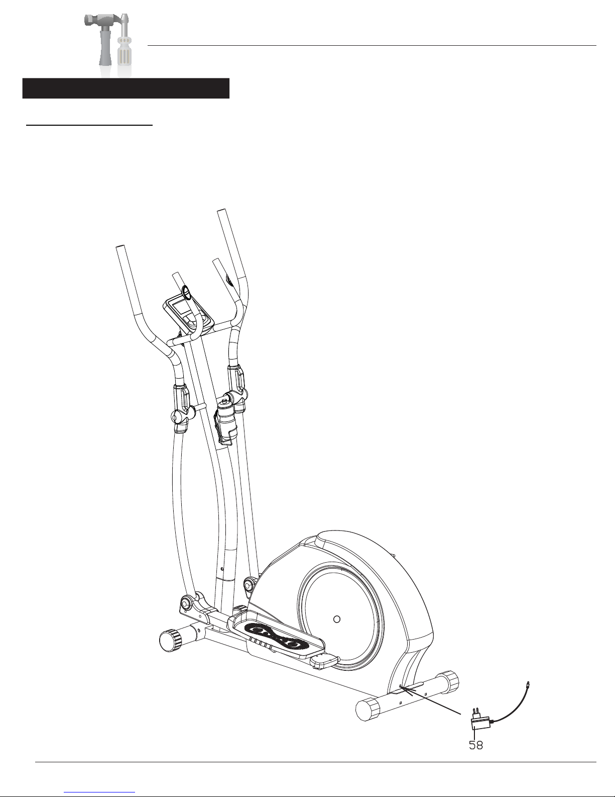
Assembly Step 8
AC Adapter Assembly
Plug in the AC Adapter (#58)male plug
into the female socket located at the rear
of the unit as shown by the arrow.
BR 2710

Safety Instructions
• Make sure all bolts are tightened.
• Check for loose parts and components
• Check to see if there are any tears or bends in the welding or metal.
Page 13BR 2710

I. To operate the monitor
A-0. Plug in the AC Adapter to power supply. You will see this first screen followed by the next one.
A-1. You may select different training mode of MANUAL, PROGRAM, USER or TARGET H.R. by pressing UP, DOWN buttons (a1).
Press MODE button to confirm. Or, you may press ST/STOP button to start training directly in MANUAL mode.
A-2. In a fresh monitor, if you start the selected mode, all function data start counting up from zero once the training starts (a2).
If you choose to preset any function target data (optional), then, the function display will count down from your preset target
value once the training starts.
A-3. During training, you may adjust resistance by pressing UP, DOWN buttons (a3). Please note each bar represents TWO
resistance levels. The bar will change up or down every two levels. During adjustment, you will see the display changes
when you press UP or DOWN button twice. There is a number (1 to 16) on the screen to show the exact resistance level.
A-4.
To reset,if during training,press ST/STOP button firstly(P will appear on the left-top corner),and then press reset button for 2 seconds.
(a1) (a2) (a3)
B. Training in MANUAL mode - press UP button until MANUAL shows up on the upper line, press MODE to confirm(b1).
(b1)MMM M
(b2) (b3) (b4)
B-1 You may press ST/STOP button to start training directly(b2), or you may press UP, DOWN buttons to adjust resistance
level (b3). During adjustment, you will see the display
changes when you press UP or DOWN buttons twice.
You may also adjust training resistance during training.
B-2 After adjustment of the training resistance, you may press
ST/STOP to start training or, optionally, set each function (b5) (b6)
data target by pressing MODE button to select the desired function you want to set target data. Then, use the UP, DOWN
buttons to set the value. Press MODE button to advanced to the next desired function area. The functions available for
preset are: Time, Distance, Calories, and Pulse in MANUAL mode.(b4)
B-3 After all settings are done, press ST/STOP button to start training. You will see each preset function data counts down from
target as soon as training starts. (b5)
B-4 Once each function target data is achieved (counts down to zero), the monitor will stop all functions (P appears on the
left-upper corner) and beep for 8 times to remind you. (b6)
B-5 You may press ST/STOP button to start training again. The function which has achieved to zero will start from previous set
data counting down, and other set function data will keep counting up or down from previous records.
MMM
MM
Computer Operation
BR 2710 Page 14

B-6 During all training period, you may press ST/STOP to stop monitor counting at anytime.
C. Training in PROGRAM mode - press UP button until PROGRAM shows up on the upper line, press MODE to confirm.
(c1) (c2)(c3)(c4)
C-1 The initial set program profile is P1 (c1 & c2). There are 12 training program profiles (P1-P12) available. You may press
UP/DOWN button to select the desired training profile. Press MODE button to confirm.
C-2 You may press ST/STOP button to start training directly(c3), or you may press UP, DOWN buttons to adjust resistance
level (c4). During adjustment, you will see the display changes when you press UP or DOWN button twice.
C-3 After adjustment of the training resistance, you may press ST/STOP to start training or, Optionally, set each function data
target by following the same procedure as stated in B-2 above. The functions available for preset are: Time, Distance,
Calories, and Pulse in PROGRAM mode.(c5)
MMM
(c5) (c6) (c7)
C-4 After all settings are done, press ST/STOP button to start training. You will see each preset function data counts down from
target as soon as training starts.(c6)
C-5 Once each function target data is achieved (counts down to zero), the monitor will stop all functions (P appears on the
left-upper corner) and beep for 8 times to remind you. (c7)
C-6 You may press ST/STOP button to start training again. The function which has achieved to zero will start from previous set
data counting down, and other set function data will keep counting up or down from previous records.
C-7 During all training period, you may press ST/STOP to stop monitor counting at anytime.
D. Training in USER mode - press UP button until USER shows up on the upper line, press MODE to confirm(d1). In USER mode,
you can set your own desired training program.
(d1) (d2) (d3) (d4)
D-1 There are 16 profile units that you can set the desired resistance level for each unit to create your own training program.
Press UP, DOWN buttons to adjust resistance level of the first
profile unit. During adjustment, you will see the display
changes when you press UP or DOWN buttons twice (d3).
Press MODE button to move to the next profile unit. Then,
use UP, DOWN buttons again to set the desired resistance (d5) (d6)
level until you've completed all 16 profile units. You may also adjust resistance during training.
D-2 After completing your own training program setting, you may press ST/STOP to start training or, optionally, set each function
data target by following the same procedure as stated in B-2 above. The functions available for preset are: Time, Distance,
Calories, and Pulse in USER mode. (d4)
D-3 After all settings are done, press ST/STOP button to start training. You will see each preset function data counts down from
target as soon as training starts. (d5)
D-4 Once each function target data is achieved (counts down to zero), the monitor will stop all functions (P appears on the
MMMM
MMMM
M
M
Computer Operation
BR 2710 Page 15

left-upper corner) and beep for 8 times to remind you.(d6)
D-5 You may press ST/STOP button to start training again. The function which has achieved to zero will start from previous set
data counting down, and other set function data will keep counting up or down from previous records.
D-6 During all training period, you may press ST/STOP to stop monitor counting at anytime.
E. Training in TARGET H.R. mode - press UP button until TARGET H.R. shows up on the upper line, press MODE to confirm.
(The monitor will first display initial set AGE 20(e1). Please input your age by pressing UP, DOWN, and MODE button to confirm.
The monitor will then display initial target heart rate percentage 55% (e2). You may press UP button to select 75%, 90% or THR
for further selection. The right-lower field of the display will show a target heart rate figure which is calculated according to your
age and selected heart rate percentage. You may follow this target heart rate figure to track your heart rate status during
training. If you select THR, the initial monitor set target heart rate figure is 100 shown on the right-lower field of the display.
You may press MODE button and use UP, DOWN buttons to set your desired target heart rate value, the setting range could
be from 30 to 240 bpm.
(e1) (e2) (e3) (e4)
E-1 You may press ST/STOP button to start training directly
(e3). Or, optionally, you may set each function data target
by following the same procedure as stated in B-2 above.
The functions available for preset are: Time, Distance, and
Calories in TARGET H.R. mode.(e4) (e5) (e6)
E-2 After all settings are done, press ST/STOP button to start training. You will see each preset function data counts down from
target as soon as training starts(e5). Once you are training in TARGET H.R. mode, the training resistance will be adjusted
automatically depends on your current heart beat. If your heart beat is very high compare to the preset target, the training
resistance will decrease immediately one level, and keep decreasing one level every 15 seconds by monitoring your
current heart beat change. If the training resistance has dropped to level one but your heart beat is still high, the monitor will
stop all functions automatically as a protective action. If your heart beat is very low compare to the preset target, the training
resistance will increase one level every 30 seconds till level 16. You will NOT be able to adjust training resistance by
yourself when you are training in Target H.R. mode.
E-3 Once each function target data is achieved (counts down to zero), the monitor will stop all functions (P appears on the
left-upper corner) and beep for 8 times to remind you.(e6)
E-4 You may press ST/STOP button to start training again. The function which has achieved to zero will start from previous set
data counting down, and other set function data will keep counting up or down from previous records.
E-5 During all training period, you may press ST/STOP to stop monitor counting at anytime.
II. Button Functions
UP To make upward adjustment to each function data or increase training resistance or select personal data setting.
DOWN To make backward adjustment to each function data or decrease training resistance or select personal data setting.
MODE To confirm function selection or data input.
RECOVERY To activate/deactivate the Heart Rate Recovery function.
RESET Press the RESET button for 2 seconds to reset current settings and switch the monitor to initial training mode.
START/STOP To start or stop training.
III. Functions
SCAN When training starts, RPM and SPEED data will alternate on display. Same thing with the Watt and Calories data.
SPEED Displays current training SPEED from 0.0 to maximum 99.9 Miles.
MMMM
M
M
Computer Operation
BR 2710 Page 16

RPM Displays current training rotations per minute.
TIME Count up - If NO preset target, Time will count up from 00:00 to maximum 99:59 with each increment of 1 second.
Count down - If training with preset Time, Time will count down from preset value to 00:00.Each preset increment
or decrement of 1 minute between 1:00 to 99:00.
DISTANCE Count up - If NO preset target, Distance will count up from 0.00 to maximum 99.90 with each increment 0.1 Mile.
Count down - If training with preset target, Distance will count down from preset value to 0.00. Each preset
increment or decrement is 0.1 Mile between 0.00 to 99.90.
CALORIES Count up - If NO preset target, Calories will count up from 0 to maximum 999 with each increment of 1 cal.
Count down - If training with preset target, Calories will count down from preset value to 0. Each preset increment
or decrement is 10 cal from 0 to 990 cal.
PULSE To display your current heart beat figures as soon as the pulse sensors are touched. The monitor will
detect your heart beat through handgrip sensors once you hold on the sensors with both hands. If you have
preset pulse target when training in Manual, Program, or User mode, the monitor will beep when your current
heart rate reaches the preset target. To select Target Heart Rate training mode for training, please refer
to the above "Training in Target Heart Rate mode". To ensure the heart rate readout is stable, please hold
the handgrip sensors with both hands during training.
RECOVERY After exercising for a period of time, keep holding on handgrips and press "RECOVERY" button. All function
display will stop except "Time" will start counting down from 00:60 - 00:59 - 00:58 - to 00:00. Please keep on
holding the handgrips until "Time" reaches 00:00. As soon as 00:00 is reached, the bottom area of display will
show your heart rate recovery status with the grade F1, F2,… F6. F1 is the best, and F6 is the worst. You may
keep on exercising to improve the heart rate recovery status day by day from F6 to F1.
** Press the RECOVERY button again to return back to the main display.
WATT Display current training watt figures.
IV. Note
1. The monitor will shut off automatically if you stop the training or button operation for 4 - 5 minutes. All training data will be kept
and reappeared again when you press any button.
2. The monitor is powered through an AC adaptor (DC 9V, 800mA). Please plug in power supply before using the monitor.
Computer Operation
BR 2710 Page 17

Troubleshooting
BR 2710 Page 18
Troubleshooting
If the computer is not picking up your hand pulse signal (or you are getting
inaccurate readings), please adjust the following:
1. Slightly moisten/dampen the palms with water so the sensors can detect a
pulse signal.
2. Do not grip the sensors too tightly. Only moderate pressure need be applied.
Gripping the sensors too tightly restricts and seizes detection of your pulse.
3. Remove any rings or jewelry to prevent interference.
4. Check to ensure all pulse sensor wires are properly connected and are
not damaged.
You may need to refer to installation/assembly directions for the pulse sensor
wires in this manual.
If the computer is not displaying the CALORIES/DISTANCE/TIME/(ETC.) functions
(or you are getting inaccurate readings), please adjust the following:
1. Check to ensure all computer sensor wires are properly connected and are
not damaged.
You may need to refer to installation/assembly directions for the sensor wires
in this manual.
If the computer display is blank & not displaying any data (or does not appear to
power on), please adjust the following:
1. Check to ensure all sensor wires are all properly connected and are
not damaged.
2. Check to ensure the AC Adapter* or Batteries* are properly plugged in or
fully charged.
Troubleshoot Area
HAND PULSE SIGNAL
CALORIES/DISTANCE/
TIME/(ETC.)
COMPUTER Display
(AFTER COMPLETE ASSEMBLY)
Solution
*Please check your product manual to determine if your model uses either
1. an AC Adapter, or 2. Batteries to power your unit.
For your safety, please do not discard this Troubleshooting sheet or the Owner’s Manual,
and keep them in a place where you can easily access/refer to them at any time.
If you are still having any troubleshooting issues, please contact our Customer Support
for further assistance.
Table of contents
Other body Power Elliptical Trainer manuals


Popular Elliptical Trainer manuals by other brands


ICON Health & Fitness
ICON Health & Fitness Pro-Form Carbon EL user manual

SportsArt Fitness
SportsArt Fitness 805P Repair manual

Vision Fitness
Vision Fitness X6150 Assembly guide

Horizon Fitness
Horizon Fitness ANDES 6 owner's manual

NordicTrack
NordicTrack NTEL59010 user manual

Tunturi
Tunturi C6 owner's manual