body Power Trio Trainer BRT5088 User manual
BRT5088
OWNER’S MANUAL
This product is intended for indoor, home use only and is not to be used in a commercial setting.
U.S. Patent number US9474925B1

This page is left blank intentionally


BRT5008 Page 1
PLEASE KEEP THESE INSTRUCTIONS FOR FUTURE USE & REFERENCE.
DO NOT DISCARD.
WARNING: SERIOUS INJURIES AND EVEN DEATH CAN OCCUR IF THE PROPER SAFETY PRECAUTIONS
ARE NOT FOLLOWED.
The diagram below highlights and reviews many of the important Safety and Warning labels also found on the unit.
Please ensure any user of the unit familiarizes themselves with this Safety and Warning guidelines before use.

BRT5008 Page 2
Before you undertake any exercise program, please be sure to
consult with your doctor.
Frequent strenuous exercise should be approved by your
doctor and proper use of your product is essential.
Excessive or incorrect training may result in health injuries.
Please read this manual carefully before commencing the
assembly of your product or starting to exercise.
• Please keep all children away from this item when in use.
Do not allow children to climb or play on this item when it
is not in use.
• Supervise teenagers while they use this unit.
• For your own safety, always ensure that there are at least
3 feet of free space in all directions around your product
while you are exercising.
• Regularly check to see that all nuts, bolts and ttings are
securely tightened. Periodically check all moving parts for
obvious signs of wear or damage.
• Any adjustment devices that could interfere with the user’s
movement of this unit should not be left projecting.
• Clean only with a damp cloth, do not use solvent
cleaners. Lubricate the moving parts of your unit every 30
days with a silicone-based grease or product.
If you are in any doubt, do not use your product; contact
CUSTOMER SUPPORT.
• Before use, always ensure that your product is positioned
on a solid, hard-at surface.
• Do not place on carpet. If necessary, use a rubber mat
underneath to reduce the possibility of slipping.
• Always wear appropriate clothing and footwear such as
training shoes when exercising. Do not wear loose clothing
that could become caught in moving parts during exercise.
• Do not use this unit if it is not functioning properly or if it is
not fully assembled.
• Do not use this unit for commercial purposes. This unit is
for home use only.
• Before use, you must read and understand all instructions
& warnings stated in this Owner’s Manual as well as post-
ed on the equipment.
• It is the facility owner’s responsibility to properly instruct
users on the proper operation of the equipment and to
warn them of the potential hazards.
• If at any time during exercise you feel faint, dizzy or
experience pain, stop and consult your physician.
Your product is intended for use in clean dry conditions. You
should avoid storage in excessively cold or damp places as
this may lead to corrosion and other related problems.
If you have any questions concerning the assembly of your
item or if any parts are missing, please DO NOT RETURN
THE ITEM TO THE STORE OR CONTACT THE
RETAILER.
Our dedicated customer service sta can help you with
any questions you may have regarding the assembly of this
unit and can also mail you replacement parts.
Customer Support is open 9:00 a.m. to 5:00 p.m. (Pacic
Time) Monday through Friday.
Please contact us by any of the following means :
Hupa International, Inc.
21717 Ferrero Parkway, Walnut, CA 91789
Telephone: 1 (888) 266 - 6789
Fax: 1 (909) 598 - 6707
Email: [email protected]
Hupa International warrants your product is free of any defects
in workmanship and materials for a period of 1 year for the
frame and 90 days on all parts if the item is used for the
intended purpose, properly maintained and not used
commercially.
Any alterations or incorrect assembly of the product will void
this warranty.
Proof of purchase must be presented for any warranty vali-
dation (no exceptions). This warranty applies to the original
purchaser only and is not transferable.
This warranty covers parts damaged due to defect in work-
manship and materials; it does not cover abuse or damages
caused during use, storage or assembly. During the warranty
period, Hupa International reserves the right to:
1. provide replacement parts to the purchaser in an eort to
repair the item.
2. repair the product returned to our warehouse
(at purchaser’s cost).
3. replace the product if neither of the two previously
- Ruler with both Metric and English measurements
- 2 x Adjustable Wrenches
- 1 x Philips (”Crosshead”) Screw Driver
Your product is suitable for users weighing:
275 pounds or less
General Information
Safety Storage and Use
Questions
Customer Support
Warranty
Assembling Tools
Weight Limit

BRT5008 Page 3
Before Assembly
1. Take a few minutes to familiarize yourself with the parts and hardware included with your product.
2. The assembly may require two people.
3. Check the frame for any damage and check any wiring (if present) for rips or tears. If you detect damage, rips, or
tears, please contact our Customer Support Team before beginning any assembly.
4. Make sure all the hardware needed is included.
5. It is very important to follow the assembly instructions correctly and to make sure all parts are attached correctly and
rmly tightened when the assembly process is complete.
6. Parts that are not tightened correctly will seem loose and can cause irritating noises and will cause damage to the
equipment.
1. It is only necessary to tighten the bolts and nuts to “nger tight” during the assembly process. This will make it
easier to complete certain steps by allowing more tolerance for all the parts to t properly.
2. Do not tighten all the nuts onto the bolts securely until after you have completed assembly of your product.
3. Use wrenches, pliers, or ratchet and sockets to tighten the bolts and nuts.
4. The Nylon Nut should thread onto the Hex Bolt until the end of the Hex Bolt has passed through the Nylon insert in-
side the Nut. Please follow this guideline every time you see this Nylon Nut icon throughout the assembly steps.
Nylon Lock Safety Nuts
Tools Required For Assembly
WARNING
PLEASE NOTE : Many of the parts and hardwares listed on the parts list are already pre-assembled or
installed on the unit.
Tool Description/Purpose
Ruler (with both Metric and English measurements)
QTY: 1
Use to measure the length or size of hardware including
bolts to ensure you are using the correct part.
Adjustable or at wrenches
QTY: 2
Use to securely install parts including nuts and bolts.

BRT5008 Page 4
Part Listing
The following parts list describes all of the parts illustrated in the exploded diagram on the following page.
PLEASE NOTE: most of these parts are already pre-assembled on your unit.
# Description
01 Main Frame
02 Seat Post
03 Rear Stabilizer
04 Front Stabilizer
05L/05R Left/Right Handle Bar
06L/06R Left/Right Pedal
07 Foot Pedal
08 Pedal Connection Joint
09L/09R Left/Right Coupler Bar
10 Pulse Handle Bar
11 Monitor
12 Center Post
13 Rear Handle Bar
14 Reinforcement Plate
15 Cushion
16 Seat Cushion Tube
17 Arc Washer (M8)
18 Cap Nut (M8)
19 Carriage Bolt (M8x73 mm)
20 Handlebar Axle
21 Hex Bolt (M10x55 mm)
22 Hex Bolt (M10x45 mm)
23 Carriage Bolt (M10x57 mm)
24 Washer (M8)
25 Right Pedal Hinge Bolt (1/2”x89 mm)
26 Left Pedal Hinge Bolt (1/2”x89 mm)
27 Nylon Nut (M10)
28 Cap Nut (M10)
29 Left Nylon Nut (with BLACK inner nylon ring)
(B0.5x20 S19)
30 Right Nylon Nut (with White inner nylon ring)
(B0.5x20 S19)
31 Arc Washer (M10)
32 Spring Washer (1/2")
33 Washer (M10)
34 Bolt Cap (S17)
35 Bolt Cap (S13)
36 Knob Bolt (M8x36 mm)
37 Knob Bolt (M12x30 mm)
38 Knob Bolt (M8x37 mm)
39 Pedal Tube
# Description
40 Crankshaft
41 Bolt (M8x50 mm)
42 Washer (M8)
43 Nylon Nut (M8)
44 Bolt (M8x30 mm)
45 Carriage Bolt (M8x45 mm)
46 Bolt (M8x16 mm)
47 Bushing (Φ28x4xΦ24x12xΦ16.1 mm)
48 End Cap for Front Stabilizer
49 Hex Bolt (M6x48 mm)
50 Roller (Φ23x32xΦ6 mm)
51 Nylon Nut (M6)
52 End Cap for Rear Stabilizer
53 End Cap (ф25 mm)
54 Foam Roller
55 Hand Pulse Sensor
56 Screw (ST4.0x19 mm)
57 End Cap (ф25 mm)
58 Foam Roller
60 Square End Cap (30 mm)
61 Bushing (Φ18x3xΦ14x7xΦ10.1 mm)
62 Wire Plug
63 Sleeve (Φ32xΦ25xL83 mm)
64 Foam Roller
65 Rectangular End Cap (25x40 mm)
66 Rectangular End Cap (20x40 mm)
67 Spring Washer (M8)
68 Backrest Cushion Tube
69 Friction Belt
77 Screw (M5x12 mm)
78 Main Frame Sensor Wire
79 Center Post Sensor Wire
80 Pulse Sensor Wire
82 Wavy Washer
83 Tension Control
59 Washer (M8)

BRT5008 Page 5
Exploded View
The following diagram is provided to help you familiarize yourself with the parts and hardware that will be used during the
assembly process.
: : Not all of the parts and hardware you see here will be used while you are assembling the machine
because some of these items are already pre-installed. Please use this page only as a reference guide for parts and
hardware.
PLEASE NOTE
04
02
38
24
16A
13
14
18
42
45
46
42
15
15
46 42
05R
05L
12
11
36
19
17
18
44
77
35
11a
79
09L
78
80
06L
22
27
06R
27
22
07
43
41
07
43
59
25
27
21
34
08
26
27
21
34
08
23
31 28
23
31
28
33
27 34
27 33
34
34
34
34 34
30
32
32 29 47
47
47
47
47
47
20
48
48
49
50
51
49
50
51
52
52
53
53
53
53
54
54
55 55
56
56
57
57
58
58
63
37
60
61
60
61
61
62
62
47
60
60
09R
36
35
21
27
21
27
59
61
61
61
63
63
64
64
47
47
66
66
44
41
61
01
40
03
39
39
10
47
82
82
82
82
42 67 44
68
66
79
65
59
59
83

BRT5008 Page 6
#23
Carriage Bolt (M10x57mm)
[4 pieces]
#19
Carriage Bolt (M8x73mm)
[1 piece]
#17
Arc Washer
(M8)
[1 piece]
#28
Cap Nut (M10)
[4 pieces]
#18
Cap Nut (M8)
[3 pieces]
#29
Left Nylon Nut
[1 piece]
#30
Right Nylon Nut
[1 piece]
#20
Handlebar Axle
[1 piece]
#27
Nylon Nut (M10)
[10 pieces]
[6 pieces pre-assembled]
#43
Nylon Nut (M8)
[4 pieces]
#34
Bolt Cap (S17)
[8 pieces]
#35
Bolt Cap (S13)
[2 pieces]
#D
(S6)
[1 piece]
#A
(S17-19)
[2 pieces]
#C
(S8)
[1 piece]
#B
(S13-14-15)
[1 piece]
#38
Knob Bolt
(M8x37mm)
[1 piece]
#36
Knob Bolt
(M8x36mm)
[2 pieces]
#37
Knob Bolt
(M12x30mm)
[1 piece pre-assembled]
#32
Spring Washer
(1/2")
[2 pieces]
#67
Spring Washer
M8
[2 pieces]
#24
Washer
(M8)
[1 piece]
#31
Arc Washer
(M10)
[4 pieces]
#33
Washer
(M10)
[2 pieces
pre-assembled]
#42
Washer
(M8)
[12 pieces]
[8 pieces
pre-assembled]
#82
Wavy Washer
[4 pieces]
[2 pieces
pre-assembled]
#22
Hex Bolt (M10x45mm)
[4 pieces]
#45
Carriage Bolt
(M8x45mm)
[2 pieces]
#21
Hex Bolt (M10x55 mm)
[4 pieces pre-assembled]
#41
Bolt (M8x50 mm)
[4 pieces]
#26
Left Pedal Hinge Bolt
[1 piece]
#25
Right Pedal Hinge Bolt
[1 piece]
#44
Bolt (M8x30 mm)
[4 pieces]
[2 piece pre-assembled]
Hardware and Tool List
Bolt
Washer
Nut
Others
Tools (Included)
#59
Washer
(M8)
[8 pieces]
The following hardware is used to assemble your unit. Please take a moment to familiarize yourself with these items.
PLEASE NOTE: Most of these parts are already pre-assembled on your unit. Do not be alarmed if you see parts on this
page that are not included in your hardware packet.
#46
Bolt (M8x16 mm)
[8 pieces pre-assembled]
#77
Screw (M5x12 mm)
[2 pieces pre-assembled]

BRT5008 Page 7
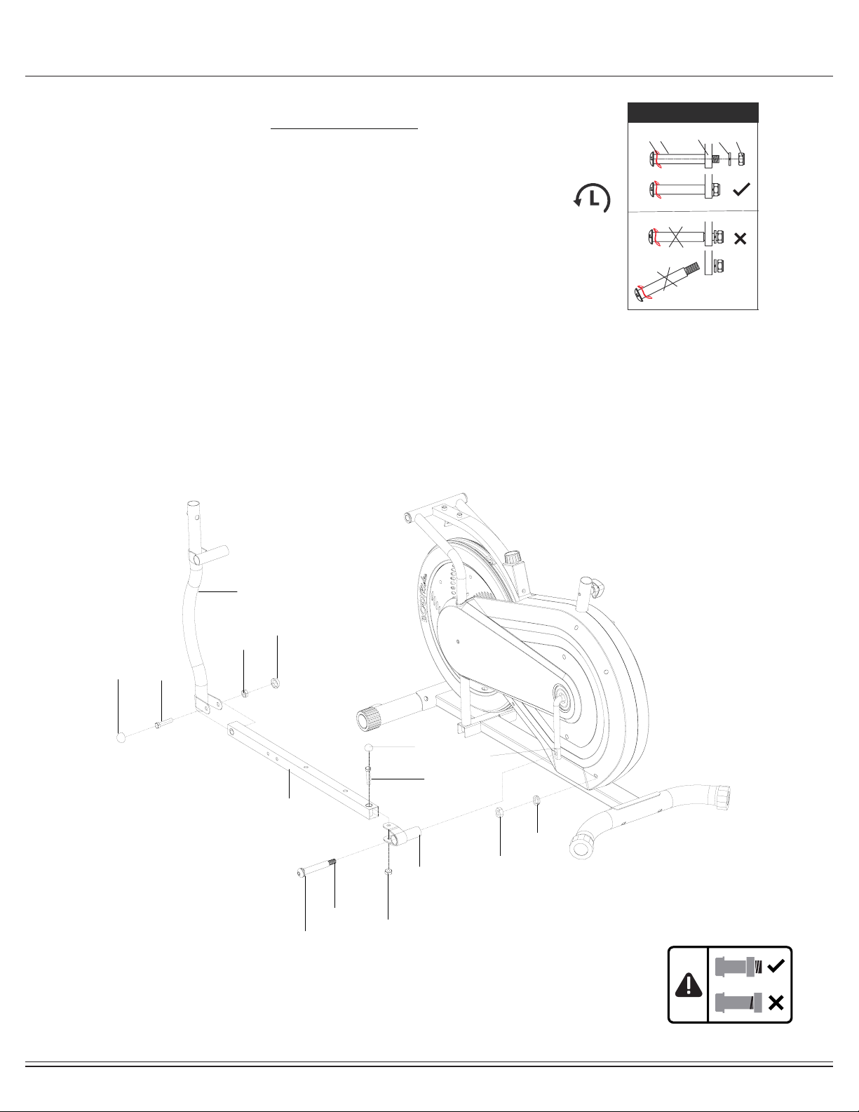
Assembly STEP 1
With the help of an assistant, attach the Rear Stabilizer
(#03) to the rear of the Main Frame (#01). Insert two
Carriage Bolts (#23) through the Rear Stabilizer
(#03) followed by the rear of the Main Frame (#01).
Secure them together using two Arc Washers (#31)
and two Cap Nuts (#28).
FRONT STABILIZER ASSEMBLY
Now, attach the Front Stabilizer (#04) to the front of
the Main Frame (#01). Insert two Carriage Bolts (#23)
through the Front Stabilizer (#04) followed by the front of
the Main Frame (#01).Secure them together using two
Arc Washers (#31) and two Cap Nuts (#28).
Note:
Please note that the Front Stabilizer (#04) has Front
Rollers that spin for ease of relocating the unit.
REAR STABILIZER ASSEMBLY Hardware Required
#23
Carriage Bolt (M10x57mm)
[4 pieces]
#31
Arc Washer
(M10)
[4 pieces]
#28
Cap Nut (M10)
[4 pieces]
Front Roller
01
03
04
23
23
31
31
28
28

BRT5008 Page 8
Assembly STEP 2
Remove the Nylon Nuts (#27),Washers (#33) and Wavy Washers
(#82) that are pre-assembled on the Handlebar Axle (#20) and set
them aside as they will be used later in this step.
Insert the Handlebar Axle (#20) through the main frame. Make
sure the Handlebar Axle (#20) is centered. If you encounter too
much friction, try using WD40 or Vaseline as a lubricant.
Then attach one Wavy Washer (#82) on each side of the Handle-
bar Axle (#20). Attach Left Coupler Bar (#09L) and Right Coupler
Bar (#09R) to the main frame via the Handlebar Axle (#20). Again,
use WD40 or Vaseline to reduce friction if needed. Once the Left
Coupler Bar (#09L) and Right Coupler Bar (#09R) are correctly
situated, fasten the end of the Handlebar Axle (#20) with a Washer
(#33) and a Nylon Nut (#27) on each side. Then cap each end
with a Bolt Cap (#34).
Note:
Make sure Left /Right Coupler Bar (#09L/09R) are at the correct side when its horizontal pivot tube, which is
welded at the top, faces the REAR of the machine as seen from the user
Hardware Required
#20
Handlebar Axle
[1 piece]
Pivot Tube
(see note below)
#27
Nylon Nut (M10)
[2 pieces]
#34
Bolt Cap (S17)
[2 pieces]
#33
Washer
(M10)
[2 pieces]
#82
Wavy Washer
[2 pieces]
82 82

BRT5008 Page 9
26 2540 4032 3229 30
LEFT CRANK RIGHT CRANK
82 82
counter-
clockwise
clockwise
Assembly STEP 3A
Hardware Required
#29
Left Nylon Nut
[1 piece]
#30
Right Nylon Nut
[1 piece]
#27
Nylon Nut (M10)
[4 pieces]
#34
Bolt Cap (S17)
[6 pieces]
#32
Spring Washer
(1/2")
[2 pieces]
#21
Hex Bolt (M10x55 mm)
[2 pieces]
#26
Left Pedal Hinge Bolt
[1 piece]
#25
Right Pedal Hinge Bolt
[1 piece]
#82
Wavy Washer
[2 pieces]
Note :
Keep the Right/Left Pedal Hinge Bolt (#25/26) perfectly
straight as they go through the Pedal Connection Joint
(#08) and the Crankshaft (#40).
If the Right/Left Pedal Hinge Bolt (#25/26) are connected
to the Crankshaft (#40) incorrectly, damage to the Right/
Left Pedal Hinge Bolt (#25/26) and Crankshaft (#40) will
occur.
The Pedal direction drawing
Remove Hex Bolts (#21) and Nylon Nuts (#27) that are
pre-assembled on the Left/Right Couple Bar (#09L/09R) and set them
aside as they will be used in later in this step.
Attach the Right Pedal Tube (#39) to the Right Coupler Bar (#09R).
Secure with one Hex Bolt (#21) and one Nylon Nut (#27).
Repeat the this process on the LEFT side.
Remove Hex Bolts (#21) and Nylon Nuts (#27) that are
pre-assembled on the Pedal Connection Joint (#08) and set them
aside as they will be used in later in this step.
Align and attach the Pedal Connection Joint (#08) to the right
Crankshaft (#40). Insert the Right Pedal Hinge Bolt (#25) with Wavy
Washer (#82) through Pedal Connection Joint (#08) and Crankshaft.
Secure the Right Pedal Hinge Bolt (#25) tightly into the Crankshaft
(#40) by turning CLOCKWISE. Then, secure with one Spring Washer
(#32) and a Right Nylon Nut [w/white inner nylon ring] (#30).
Attach the Pedal Connection Joint (#08) to the Right Pedal Tube
(#39). Insert one Hex Bolt (#21) through the upper bracket of the
Pedal Connection Joint (#08), followed by Right Pedal Tube (#39)
then the lower bracket of the Pedal Connection Joint (#08). Secure
them with one Nylon Nut (#27).
Attach three Bolt Caps (#34) over three Bolts as illustrated in the
drawing.
BRT5008 Page 10
Assembly STEP 3B
Note :
Keep the Right/Left Pedal Hinge Bolt (#25/26) perfectly
straight as they go through the Pedal Connection Joint
(#08) and the Crankshaft (#40).
If the Right/Left Pedal Hinge Bolt (#25/26) are connected
to the Crankshaft (#40) incorrectly, damage to the Right/
Left Pedal Hinge Bolt (#25/26) and Crankshaft (#40) will
occur.
26 2540 4032 3229 30
LEFT CRANK RIGHT
CRANK
82
82
counter-
clockwise
clockwise
Repeat STEP 3A on the LEFT side of the machine and
turning the Left Pedal Hinge Bolt (#26) COUNTER-CLOCKWISE.
27
34
21
26
82
34 21
27 34
29
32
09L
39
08
40

BRT5008 Page 11
Assembly STEP 4
Hardware Required
On the right side, attach Right Pedal (#06R) to the Right Pedal
Tube (#39) and secure them together using two Hex Bolts (#22)
and two Nylon Nuts (#27).
Next, attach one Foot Pedal (#07) to the front of Right Pedal Tube
(#39) using two Bolts (#41) and secure with four Washers (#59)
and two Nylon Nuts (#43).
Repeat this process on the left side using Left Pedal (#06L) and
one Foot Pedal (#07).
#27
Nylon Nut (M10)
[4 pieces]
#43
Nylon Nut (M8)
[4 pieces]
#59
Washer
(M8)
[8 pieces]
#22
Hex Bolt (M10x45mm)
[4 pieces]
#41
Bolt (M8x50 mm)
[4 pieces]
06L
06R
07
07
22
27
41
43
59
22 43
59
41
39
39
07
41
59
43
59
59
59
27 22
27
06R
BRT5008 Page 12
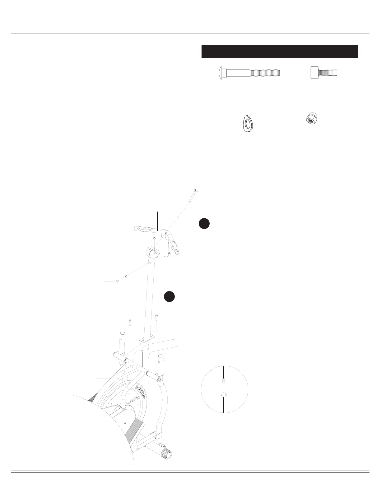
Assembly STEP 5
A. CENTER POST
Remove the Bolts (#44) that are pre-assembled on Main
Frame (#01) and set them aside as they will be used in later
in this step.
Attach the Center Post (#12) to the Main Frame (#01) and
secure them together by inserting two Bolts (#44) through
the Center Post (#12) followed by the Main Frame (#01).
Connect Main Frame Sensor Wire (#78) to the bottom end of
Center Post Sensor Wire (#79).
B. PULSE HANDLEBAR
Attach Pulse Handle Bar (#10) to Center Post (#12). Insert
one Carriage Bolt (#19) through Pulse Handle Bar (#10)
followed by Center Post (#12).Secure them together using
one Arc Washer (#17) and one Cap Nut (#18).
Hardware Required
#19
Carriage Bolt (M8x73mm)
[1 piece]
#17
Arc Washer
(M8)
[1 piece]
#18
Cap Nut (M8)
[1 piece]
#44
Bolt (M8x30 mm)
[2 pieces]
A
B
12
19
17
18
44
10
79
01
78
79
78
BRT5008 Page 13
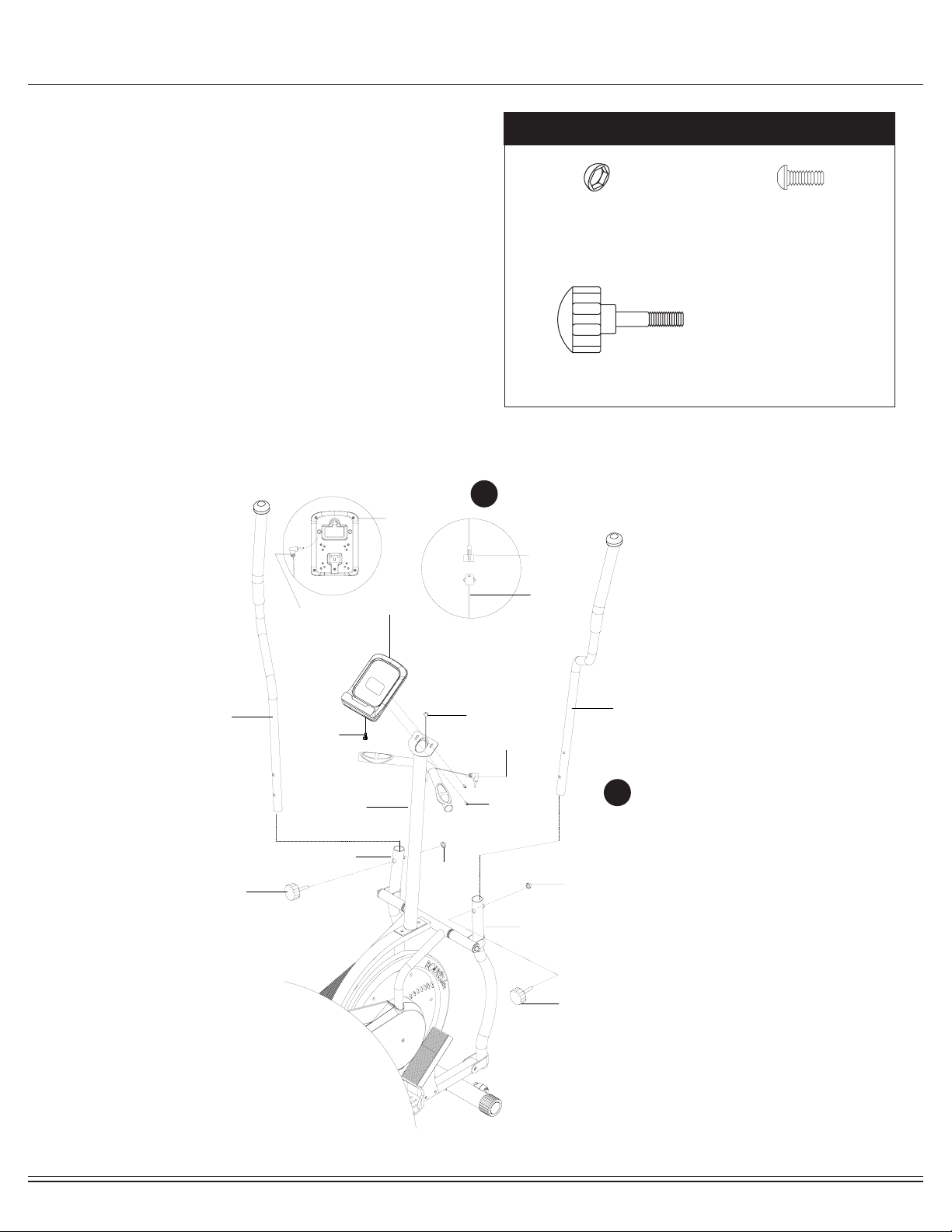
Assembly STEP 6
Hardware Required
A. COMPUTER
Remove the Screws (#77) that are pre-assembled on the
back of the monitor and set them aside as they will be used
later in this step. Connect upper end of Center Post Sensor
Wire (#79) to the Wire (#11a) on the back of Monitor (#11).
Being careful not to pinch any wires, tuck the connected wires
down the opening and mount the Monitor (#11) to the Center
Post (#12).Secure them together using two Screws (#77).
Plug Pulse Sensor Wire (#80) into hole on the back of
monitor (#11).
B. HANDLEBARS
Insert the Left Handlebar (#05L) through the Left Coupler Bar
(#09L) and Right Handlebar (#05R) through the Right
Coupler Bar (#09R). Select a height setting that is comfortable
to the user, and make sure both handlebars are set at the
same height. Secure Left and Right Handlebar (#05L/05R) in
place with two Knob Bolts (#36).Attach the Bolt Caps (#35)
over two Knob Bolts (#36) as illustrated in the drawing.
#35
Bolt Cap (S13)
[2 pieces]
#36
Knob Bolt
(M8x36mm)
[2 pieces]
#77
Screw (M5x12 mm)
[2 pieces]
A
B
11
77
11a
05R
05L
12
36
36
35
35
09R
09L
80
11a
79
11
80
79
BRT5008 Page 14
Assembly STEP 7
Hardware Required
Remove Knob Bolt (#37) that is pre-assembled on the Main
Frame (#01) and set it aside as it will be used in a later
process.
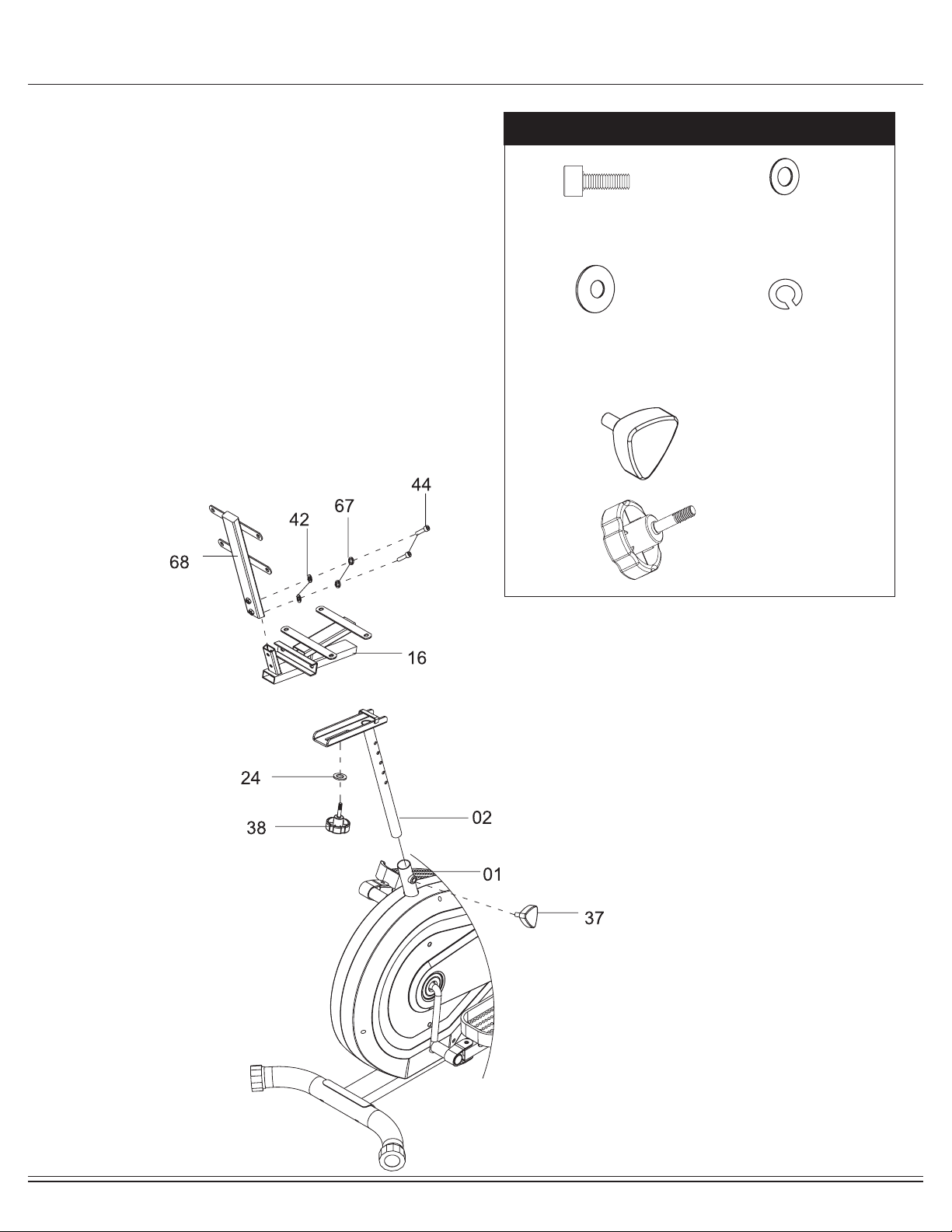
Select the desired height and secure the Seat Post (#02) to
the Main Frame (#01) using one Knob bolt (#37).
Attach the Seat Cushion Tube (#16) onto the trough of the
Seat Post (#02) with it correctly aligned and inserted into the
corresponding hole of Seat Post (#02), secure them together
by using one Washer (#24) and one Knob Bolt (#38).
Attach the Backrest CushionTube (#68) onto the trough of
the Seat Cushion Tube (#16), secure them together by using
two Bolts (#44), two Spring Washers (#67) and two Washers
(#42).
#38
Knob Bolt
(M8x37mm)
[1 piece]
#37
Knob Bolt
(M12x30mm)
[1 piece]
#24
Washer
(M8)
[1 piece]
#42
Washer (M8)
[2 pieces]
#44
Bolt (M8x30 mm)
[2 pieces]
#67
Spring Washer
(M8)
[2 pieces]

BRT5008 Page 15
Assembly STEP 8
Hardware Required
Attach the Rear Handle Bar (#13) to the bracket on the Seat
Cushion Tube (#16) and place the Reinforcement Plate (#14)
over the middle of the Rear Handle Bar (#13). Attach by
inserting two Carriage Bolts (#45) through and securing with
two Washers (#42) and two Cap Nuts (#18).
#18
Cap Nut (M8)
[2 pieces]
#42
Washer
(M8)
[2 pieces]
#45
Carriage Bolt
(M8x45mm)
[2 pieces]

BRT5008 Page 16
Assembly STEP 9
Hardware Required
THE ASSEMBLY PROCESS IS NOW COMPLETE.
However, for your own safety, please make sure to read this entire Owner’s Manual which
includes safety instructions and warnings, as well as any safety/warning labels axed to the
product before use. For your safety , please visually and functionally inspect and test the unit
after assembly is complete.
Remove Bolts (#46) and Washers (#42) that are
pre-assembled on the two Cushions (#15) and set them
aside as they will be used in a later process.
Attach one Cushion (#15) to the Seat Cushion Tube (#16).
Secure with four Washers (#42) and four Bolts (#46).
Attach another Cushion (#15) to the Backrest Cushion Tube
(#68). Secure with four Washers (#42) and four Bolts (#46).
#42
Washer
(M8)
[8 pieces]
#46
Bolt (M8x16 mm)
[8 pieces]
WARNING!
Do not remove the seat assembly
for any reason after you have
installed it.
Exercising on this unit without
the seat assembly can result in
SERIOUS INJURY.
Ensure the seat is locked in place
by tightening the two knobs prior
to use.
BRT5008 Page 17
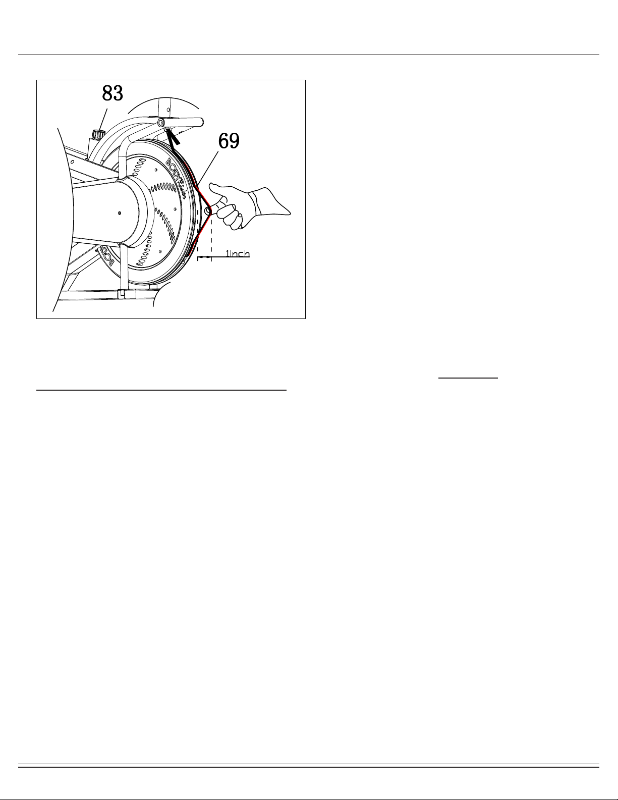
Tension Adjustment
WARNING:
If the Friction Belt (#69) is tightened to an extremely tight/taut setting against the ywheel, you may risk
damaging, over-wearing, over-stressing and/or breaking the Friction Belt (#69).
Please see below for more details to prevent damage and breakage.
1. FOR TENSION ADJUSTMENT:
Simply turn the Tension Control (#83).
• To increase tension (+ higher resistance and more dicult), turn clockwise.
• To decrease tension (- lower resistance and less dicult), turn counter-clockwise.
***WARNING: Please turn the Tension Control (#83) gently. DO NOT use excess force to avoid damaging any parts of
your unit.
2. FOR CALIBRATING TENSION ADJUSTMENT SYSTEM:
• Gently turn Tension Control (#83) counter-clockwise and keep turning until the knob can no longer turn
(i.e. decrease the tension fully).
• Adjust the Friction Belt (#69) so that when you gently tug it out away from ywheel, there is a 1" distance of
slack between the Friction Belt (#69) and the ywheel as shown in diagram.
***WARNING: It is important you check for this minimum of 1-inch distance to avoid damaging, over-wearing,
over-stressing and/or breaking the Friction Belt (#69).
NOTE:
It is normal for the Friction Belt (#69) to periodically loosen due to regular use. Repeat the below process anytime you
feel it may be necessary to recalibrate the tension adjustment system.
1-inch Distance
(use this measurement as a “test” when you gently
tug on Friction Belt (#69) away from ywheel)
NOTE:
In order to clearly show parts used in Tension Adjustment
process, this drawing has been modied and does not
show all parts nor full assembly.
Table of contents
Other body Power Elliptical Trainer manuals


Popular Elliptical Trainer manuals by other brands


Pro-Form
Pro-Form Hybrid Trainer PFEL03812.2 user manual

HEALTH RIDER
HEALTH RIDER HREVEL05983 user manual

Life Span
Life Span X-22 owner's manual

Life Fitness
Life Fitness Summit Trainer 95Le Operation manual

Pro-Form
Pro-Form 485 E Elliptical Manuale d'istruzioni

HEALTH RIDER
HEALTH RIDER 9.5 Ex Crosstrainer El Elliptical user manual