SPARTAN sport 1332N User manual
1332Crosstrainer PERFORMANCE
ITEM NO.: 1332N
OWNER’S MANUAL
IMPORTANT: Read all instructions carefully before using this product. Retain this
owner’s manual for future reference.
The specifications of this product may vary from this photo and are subject to change without
prior notice.

1
TABLE OF CONTENTS
IMPORTANT SAFETY INSTRUCTIONS ------------------------------------------- 2
PARTS LIST ------------------------------------------------------------------------------- 3
TOOLS -------------------------------------------------------------------------------------- 5
HARDWARE LISTAND ASSEMBLY PART --------------------------------------- 6
EXPLODED VIEW ----------------------------------------------------------------------- 7
ASSEMBLY INSTRUCTIONS --------------------------------------------------------- 8
HOW TO MOVE THE ELLIPTICALTRAINER ------------------------------------ 24
OPERATING THE COMPUTER ------------------------------------------------------ 25
ADJUSTMENTS -------------------------------------------------------------------------- 27
MAINTENANCE -------------------------------------------------------------------------- 28
TROUBLESHOOTING ------------------------------------------------------------------ 28
WARM UPAND COOL DOWN ROUTINE ----------------------------------------- 29

2
IMPORTANT SAFETY INSTRUCTIONS
Basic precautions should always be followed, including the following important
safety instructions when using this equipment. Read all instructions before using
this equipment.
1. Read all instructions and follow it carefully before using this equipment. Make sure the
equipment is properly assembled and tightened before use.
2. Before exercise, in order to avoid injuring the muscle, warm-up exercises are
recommended.
3. Please make sure all parts are not damaged and fixed well before use. This
equipment should be placed on a flat surface when using. Using a mat or other
covering material on the ground is recommended.
4. Please wear proper clothes and shoes when using this equipment; do not wear clothes
that might catch any part of the equipment.
5. Do not attempt any maintenance or adjustments other than those described in this
manual. Should any problems arise, discontinue use and consult your local dealer.
6. Be careful when step on or leave the pedal always hold the handlebars first. Make the
pedal at your side at the lowest position, step on the pedal, and stride over the main
frame then step on the other pedal. When using, please hold the handlebar by hands,
make the pedals running smoothly by push or pull handlebars, then run the equipment
regularly by cooperation of hands and feet. After exercise, please also make one
pedal at the lowest position and leave your foot on the higher pedal first and then
another.
7. Do not use the equipment outdoors.
8. This equipment is for household use only. It is not a commercial model.
9. Only one person at a time should use this equipment.
10. If you feel any chest pains, nausea, dizziness, or short of breath, you should stop
exercising immediately and consult your physician before continuing.
11. Care should be taken in mounting or dismounting the equipment.
12. Do not allow children to use or play on the equipment. Keep children and pets away
from the equipment while in use. This machine is designed for adults use only. The
minimum free space required for safe operation is not less than two meters.
13. The maximum weight capacity for this product is 110 kg.
WARNING: Before beginning any exercise program consult your
physician. This is especially important for people who are over 35 years old or who
have pre-existing health problems. Read all instructions before using any fitness
equipment. Do not operate this exercise equipment without properly fitted guards,
as the moving parts can present a risk of serious injury if exposed.
CAUTION:Read all instructions carefully before operating this product.
Retain this Owner’s Manual for future reference.

3
PARTS LIST
No.
Description
Qty
No.
Description
Qty
001
Main Frame
1
020
U Shape Bracket
2
002L
Left Foot Bar
1
021
Nylon Nut M8
2
002R
Right Foot Bar
1
022
Washer Ø16xØ8x1.5
2
003L
Left Handrail Arm
1
023
Hexagon Head Bolt M8x45
2
003R
Right Handrail Arm
1
024
Nylon Nut M6
10
004L
Left Handrail Ø32x1.5
1
025
Washer Ø6
7
004R
Right Handrail Ø32x1.5
1
026
Hexagon Head Bolt M6x40
6
005
Front Post
1
027
Tension Cable L=1800
1
006
Handlebar Ø25x1.5
1
028
Bolt Cap S13
2
007
Front Stabilizer Ø60x1.5x480
1
029
Cross Recessed Pan Head
Tapping Screw ST4.2x25
11
008
Rear Stabilizer
1
030L
Foot Bar Cover-A
2
009
Carriage Bolt M8x70
2
030R
Foot Bar Cover-B
2
010L
Front Left Stabilizer End Cap Ø60
1
031
Big Washer Ø6
2
010R
Front Right Stabilizer End Cap
Ø60
1
032
Hexagon Socket Flat Head Cap
Bolt Ø10x45
2
011
Big Curve Washer Ø20xØ8
10
033
Left Foot Pedal 395x150x65
1
012
Cap Nut M8
2
034
Right Foot Pedal 395x150x65
1
013L
Bolt for left U Shape Bracket 1/2”
1
035
Rear Left Stabilizer End Cap Ø60
1
013R
Bolt for right U Shape Bracket 1/2”
1
036
Rear Right Stabilizer End Cap
Ø60
1
014L
Left Nylon Nut 1/2”
1
037
Cover Cap Ø40xØ25x10
2
014R
Right Nylon Nut 1/2”
1
038
Hexagon Socket Pan Head Cap
Bolt M8x15
8
015
Wave Washer Ø28xØ17x0.3
2
039
Powder Metal Bushing
Ø14.2xØ10.2x10
4
016
Powder Metal Bushing
Ø24.5xØ16x14
4
040
Hexagon Socket Pan Head Cap
Bolt M8x20
2
017
Spring Washer Ø20
2
041
Spring Washer Ø8
8
018
Bearing (60002Z)
2
042
Washer Ø38x3
2
019
Washer 7/8"
1
043
Powder Metal Bushing
Ø38xØ32xØ19x14
4

4
PARTS LIST
No.
Description
Qty
No.
Description
Qty
044
Carriage Bolt M6x35
4
064
Extension Sensor Wire
L=1100 mm
1
045
Curve Washer Ø6
4
065
Sensor with Wire L=1600 mm
1
046
Big Washer Ø8
2
066
Cross Recessed Pan Head
Tapping Screw ST2.9x12
2
047
Cross Recessed Pan Head Bolt
M6x10
1
067
Left Cover
1
048
Plastic Bushing Ø32xØ16x5xØ50
2
068
Right Cover
1
049L
Left HandrailArm Cover-A
1
069
Bearing Cup
2
049R
Right Handrail Arm Cover-A
1
070
Bearing
2
050L
Left HandrailArm Cover-B
1
071
Bearing Nut I 15/16”
1
050R
Right Handrail Arm Cover-B
1
072
Bearing Nut II 7/8”
1
051
Tension Control Knob
1
073
Washer Ø34.5xØ23x2.5
1
052
Cross Recessed Pan Head
Tapping Screw ST4.2x20
4
074
Hexagon Nut 7/8”
1
053
Computer
1
075
Belt Pulley with Crank 6.5”/Ø260
1
054
Rear Decorative Cover for Front
Post
1
076
Hexagon Socket Pan Head Cap
Bolt M8x25
1
055
Hand Pulse Sensor with Wire
L=750 mm
2
077
M10x1 Nut for Flywheel
2
056
Handrail Foam Grip
Ø31xØ37x480
2
078
Flywheel Ø230x40x32
1
057
Handlebar Foam Grip
Ø27xØ33x360
2
079
Belt PJ400 J6
1
058
Handrail End Cap Ø32x1.5
2
080
Idler Arm
1
059
Handlebar End Cap Ø28x1.5
2
081
Cross Recessed Pan Head Bolt
M6x15
2
060
Cross Recessed Pan Head
Drilling Screw with Tapping Screw
Thread ST4.2x25
6
082
Eyebolt M6x36
2
061
Curve Washer Ø20xØ5.2
1
083
Tension Bracket
2
062
Cross Recessed Pan Head Bolt
M5x55
1
084
Nut M6
2
063
Adjustable Leveler M10
2
085
Spring Washer Ø6
2

5
PARTS LIST
TOOLS
No.
Description
Qty
No.
Description
Qty
086
Power Metal Bushing Ø18xØ8x5
4
094
Cross Recessed Pan Head
Tapping Screw ST4.2x12
8
087
Nut M10
2
095
Rubber Cover
2
088
Cross Recessed Pan Head Bolt
M5x10
4
096
Hexagon Socket Pan Head Cap
Bolt M8x70
2
089
Hexagon Socket Pan Head Cap
Bolt M8x10
1
097
Cross Recessed Pan Head
Drilling Screw with Tapping Screw
Thread ST4.2x20
8
090
Front Decorative Cover for Front
Post
1
098
Cross Recessed Pan Head
Tapping Screw ST2.9x16
1
091
Left Decorative Cover
1
099
Washer Ø10xØ141
2
092
Right Decorative Cover
1
100
Wave Washer Ø26xØ19x0.3
2
093
Curve Washer Ø16xØ8
2
Multi Hex Tool
S10, S13, S17, S19
1 PC
Allen Wrench S6
1 PC
Allen Wrench S8
1 PC
Multi Hex Tool with Phillips Screwdriver
S10, S13, S14, S15
1 PC

6
(13R) Bolt for right U Shape Bracket
1 PC
(14R) Right Nylon Nut 1 PC
(15) Wave Washer 1 PC
(17) Spring Washer 1 PC
(96) Hexagon Socket
Pan Head Cap
2 PCS
HARDWARE LIST AND ASSEMBLY PART
(13L) Bolt for left U Shape Bracket 1 PC
(14L) Left Nylon Nut 1 PC
(15) Wave Washer 1 PC
(17) Spring Washer 1 PC
(94) Cross Recessed Pan
Head Tapping Screw
8 PCS
(97) Cross Recessed Pan
Head Drilling Screw with
Tapping Screw Thread
4 PCS
(9) Carriage Bolt 2 PCS
(11) Big Curve Washer 2 PCS
(12) Cap Nut 2 PCS
(24) Nylon Nut 6 PCS
(25) Washer 6 PCS
(26) Hexagon Head Bolt 6 PCS
(28) Bolt Cap
2 PCS
(11) Big Curve Washer
2 PCS
(24) Nylon Nut 4 PCS
(44) Carriage Bolt 4 PCS
(45) Curve Washer 4 PCS
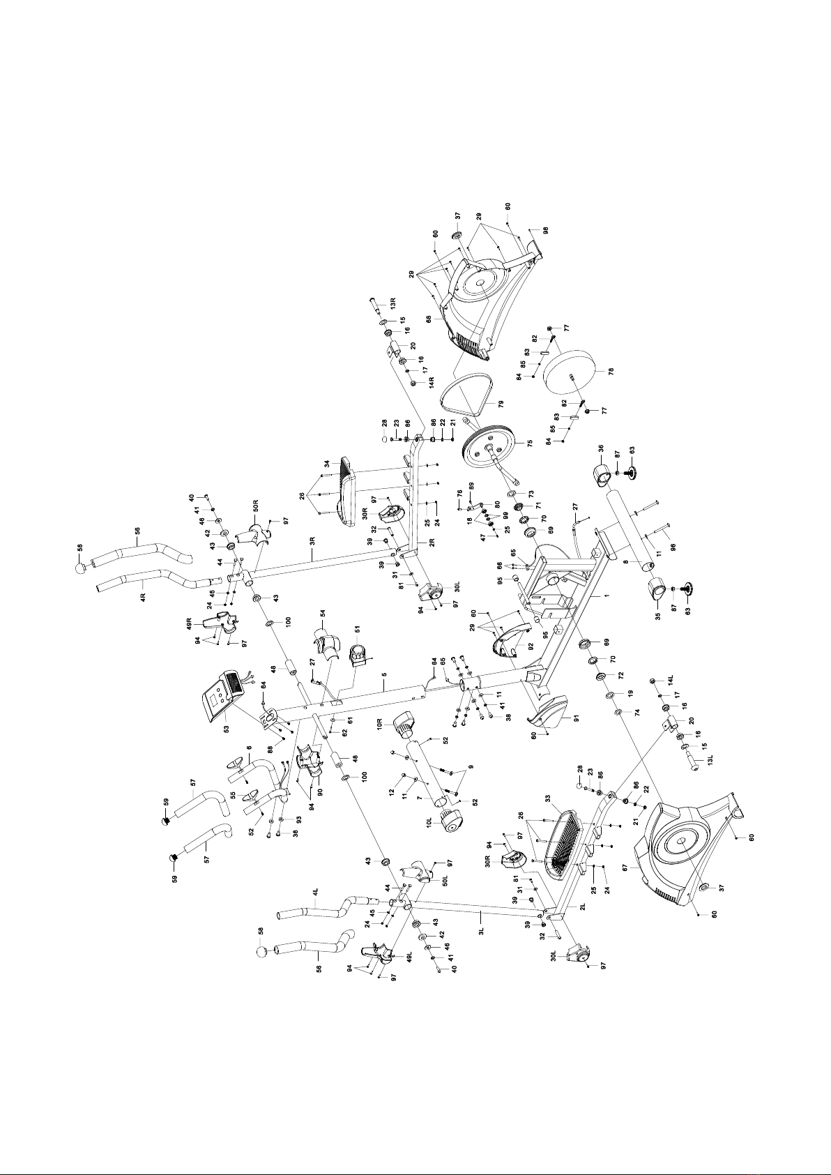
7
EXPLODED VIEW

8
ASSEMBLY INSTRUCTIONS
STEP 1
Position the Front Stabilizer (7) in front of the Main Frame (1) and align bolt holes.
Attach the Front Stabilizer (7) onto the front curve of the Main Frame (1) with two Carriage
Bolts (9), two Big Curve Washers (11), and two Cap Nuts (12). Tighten cap nuts with the
Multi Hex Tool with Phillips Screwdriver provided.
Hardware:
(9) Carriage Bolt 2 PCS
(11) Big Curve Washer 2 PCS
(12) Cap Nut 2 PCS

9
STEP 2
Install twoAdjustable Levelers (63) with two Nuts (87) onto the Rear Stabilizer (8).
Position the Rear Stabilizer (8) behind the Main Frame (1) and align bolt holes.
Attach the Rear Stabilizer (8) onto the rear curve of the Main Frame (1) with two Hexagon
Socket Pan Head Cap Bolts (96) and two Big Curve Washers (11). Tighten cap nuts with
the S6 Allen Wrench provided.
Hardware:
(96) Hexagon Socket
Pan Head Cap
2 PCS
(11) Big Curve Washer
2 PCS
Allen Wrench S6
10
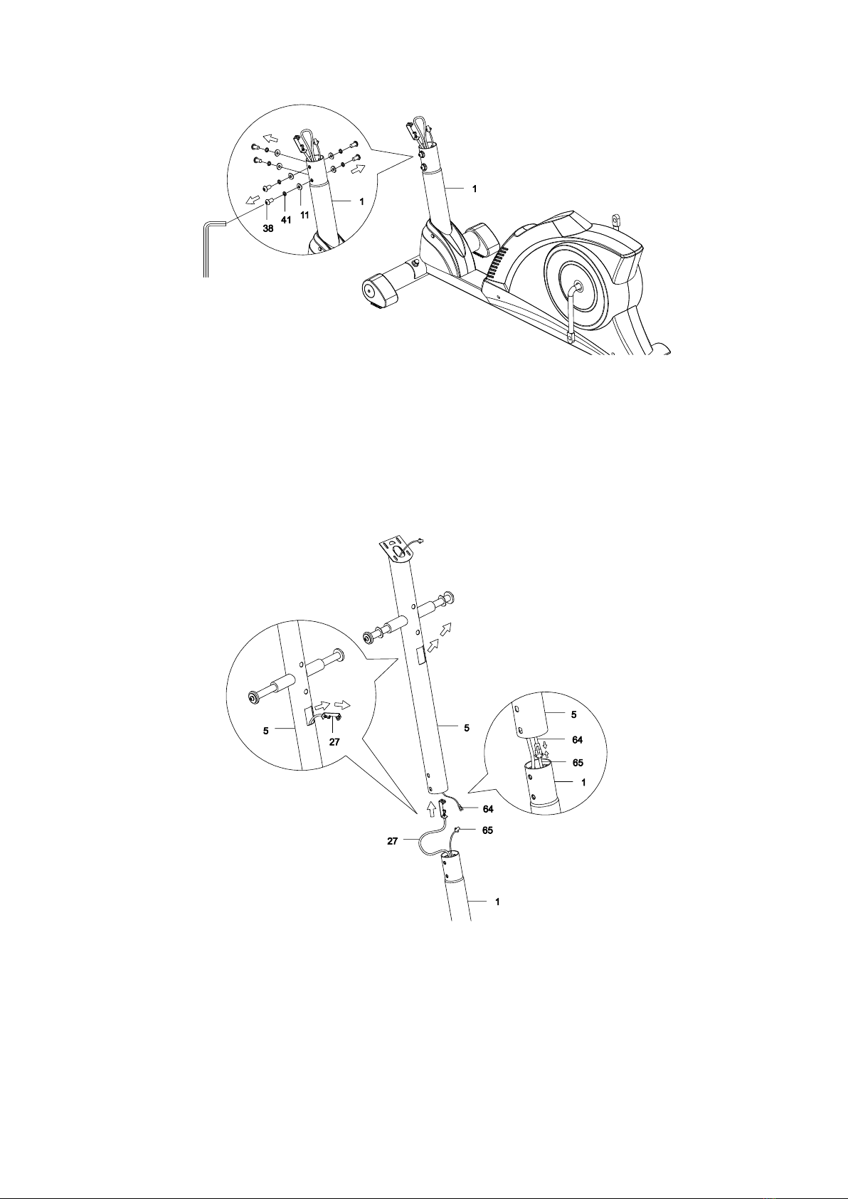
STEP 3
Remove six Hexagon Socket Pan Head Cap Bolts (38), six Spring Washers (41), and six Big
Curve Washers (11) from the Main Frame (1). Remove bolts with the S6 Allen Wrench
provided.
STEP 4
It is recommended to have a second person assist with this step. One person should hold
the Front Post (5) in place while the other person to connect the wires.
Insert the Tension Cable (27) through into the bottom hole of the Front Post (5) and pull it
out from the square hole of the Front Post (5).
Connect the Sensor Wire (65) from the Main Frame (1) to the Extension Sensor Wire (64)
from the Front Post (5).
Allen Wrench S6
11
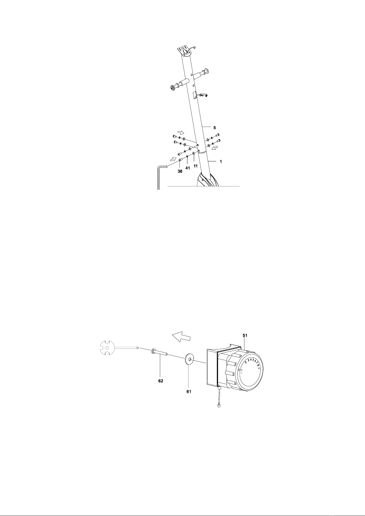
STEP 5
Insert the Front Post (5) onto the tube of the Main Frame (1) and secure with six Hexagon
Socket Pan Head Cap Bolts (38), six Spring Washers (41), and six Big Curve Washers (11)
that were removed. Tighten bolts with the S6Allen Wrench provided.
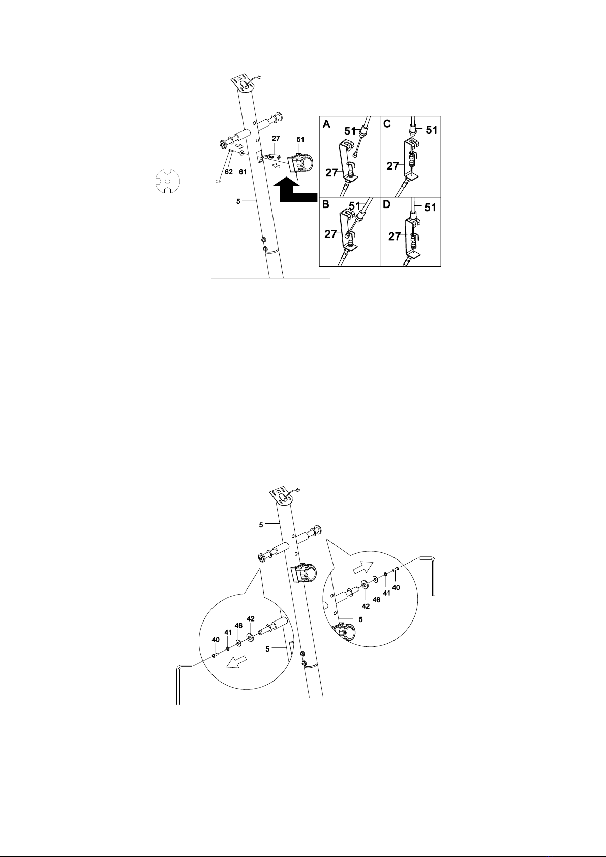
STEP 6
Remove one Cross Recessed Pan Head Bolt (62) and one Curve Washer (61) from the
Tension Control Knob (51). Remove bolt with the Multi Hex Tool with Phillips Screwdriver
provided.
Allen Wrench S6
12
STEP 7
Put the cable end of resistance cable of Tension Control Knob (51) into the cable lock of
Tension Cable (27), see Figure A.
Pull the resistance cable of Tension Control Knob (51) up and force it into the slot of metal
bracket of Tension Cable (27), see Figure B.
Insert the metal fitting on the resistance cable of Tension Control Knob (51) into the hole at
the end of the slot in the metal bracket of Tension Cable (27), see Figure C.
Connect the resistance cable of Tension Control Knob (51) to Tension Cable (27) complete,
see Figure D.
Attach the Tension Control Knob (51) onto the Front Post (5) with one Cross Recessed Pan
Head Bolt (62) and one Curve Washer (61) that were removed. Tighten bolt with the Multi
Hex Tool with Phillips Screwdriver provided.
STEP 8
Remove two Hexagon Socket Pan Head Cap Bolts (40), two Spring Washers (41), two Big
Washers (46), and two Washers (42) from the left and right horizontal axes of the Front Post
(5). Remove bolts with the S6Allen Wrench provided.
Allen Wrench S6
Allen Wrench S6

13
STEP 9
Attach the Left HandrailArm (3L) onto the left horizontal axis of the Front Post (5) with one
Hexagon Socket Pan Head Cap Bolt (40), one Spring Washer (41), one Big Washer (46),
and one Washer (42) that were removed. Tighten bolt with the S6 Allen Wrench provided.
STEP 10
Attach the Right Handrail Arm (3R) onto the right horizontal axis of the Front Post (5) with
one Hexagon Socket Pan Head Cap Bolt (40), one Spring Washer (41), one Big Washer (46),
and one Washer (42) that were removed. Tighten bolt with the S6 Allen Wrench provided.
Allen Wrench S6
Allen Wrench S6

14
STEP 11
Attach the left U Shape Bracket (20) to the left Crank (75) with one Bolt for left U Shape
Bracket (13L), one Wave Washer (15), one Spring Washer (17), and one Left Nylon Nut
(14L). Tighten bolt and nylon nut with the S8Allen Wrench and Multi Hex Tool provided.
Install a Bolt Cap (28) onto the Hexagon Head Bolt (23).
NOTE: Bolt for left U Shape Bracket (13L) is marked “L” for Left.
Hardware & Assembly Part:
Bolt is marked “L” for Left.
(13L) Bolt for left U Shape Bracket 1 PC
(14L) Left Nylon Nut 1 PC
(15) Wave Washer 1 PC
(17) Spring Washer 1 PC
(28) Bolt Cap
1 PC
Allen Wrench S8

15
STEP 12
Attach the left U Shape Bracket (20) to the right Crank (75) with one Bolt for right U Shape
Bracket (13R), one Wave Washer (15), one Spring Washer (17), and one Right Nylon Nut
(14R). Tighten bolt and nylon nut with the S8 Allen Wrench and Multi Hex Tool provided.
Install a Bolt Cap (28) onto the Hexagon Head Bolt (23).
NOTE: Bolt for right U Shape Bracket (13R) is marked “R” for Right.
Hardware & Assembly Part:
(13R) Bolt for right U Shape Bracket
1 PC
(14R) Right Nylon Nut 1 PC
(15) Wave Washer 1 PC
(17) Spring Washer 1 PC
(28) Bolt Cap
1 PC
Bolt is marked “R” for Right.
Allen Wrench S8
16
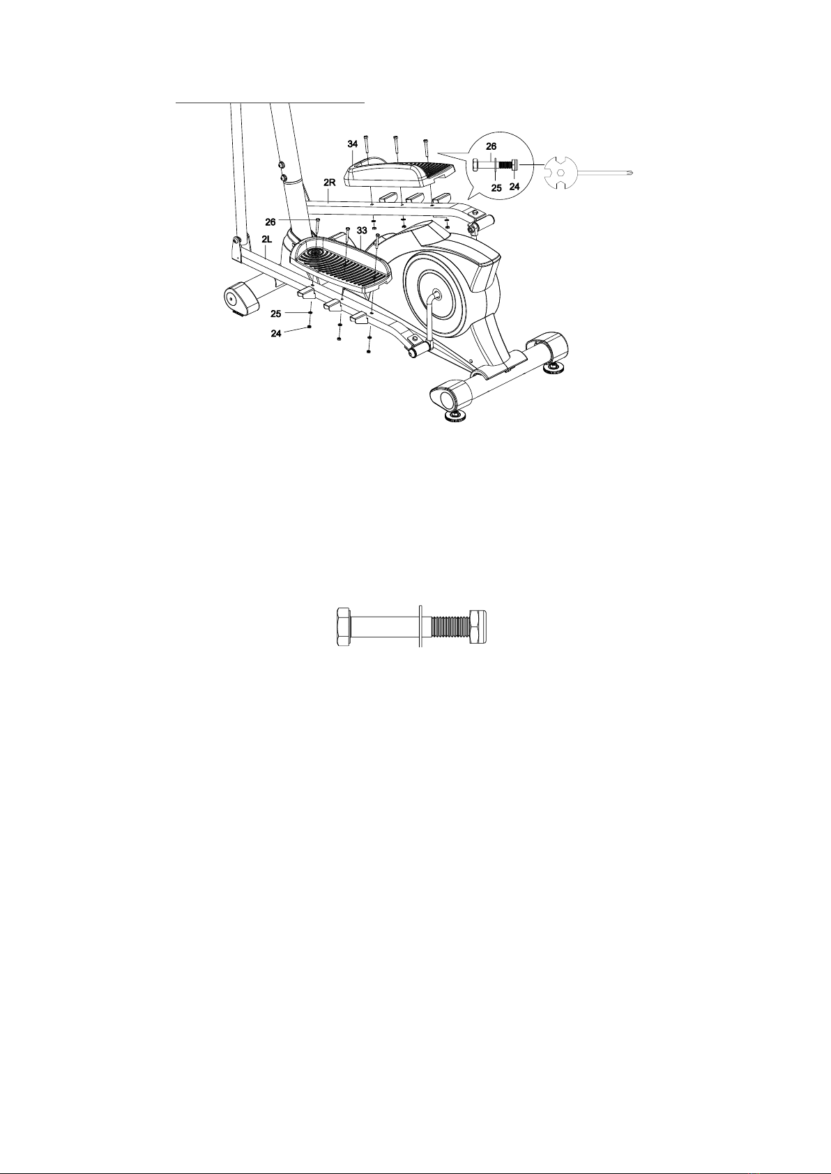
STEP 13
Attach the Left Foot Pedal (33) onto the Left Foot Bar (2L) with three Hexagon Head Bolts
(26), three Washers (25), and three Nylon Nuts (24). Tighten the nylon nuts with the Multi
Hex Tool with Phillips Screwdriver provided.
Attach the Right Foot Pedal (34) onto the Right Foot Bar (2R) with three Hexagon Head
Bolts (26), three Washers (25), and three Nylon Nuts (24). Tighten the nylon nuts with the
Multi Hex Tool with Phillips Screwdriver provided.
Hardware:
(24) Nylon Nut 6 PCS
(25) Washer 6 PCS
(26) Hexagon Head Bolt 6 PCS
17
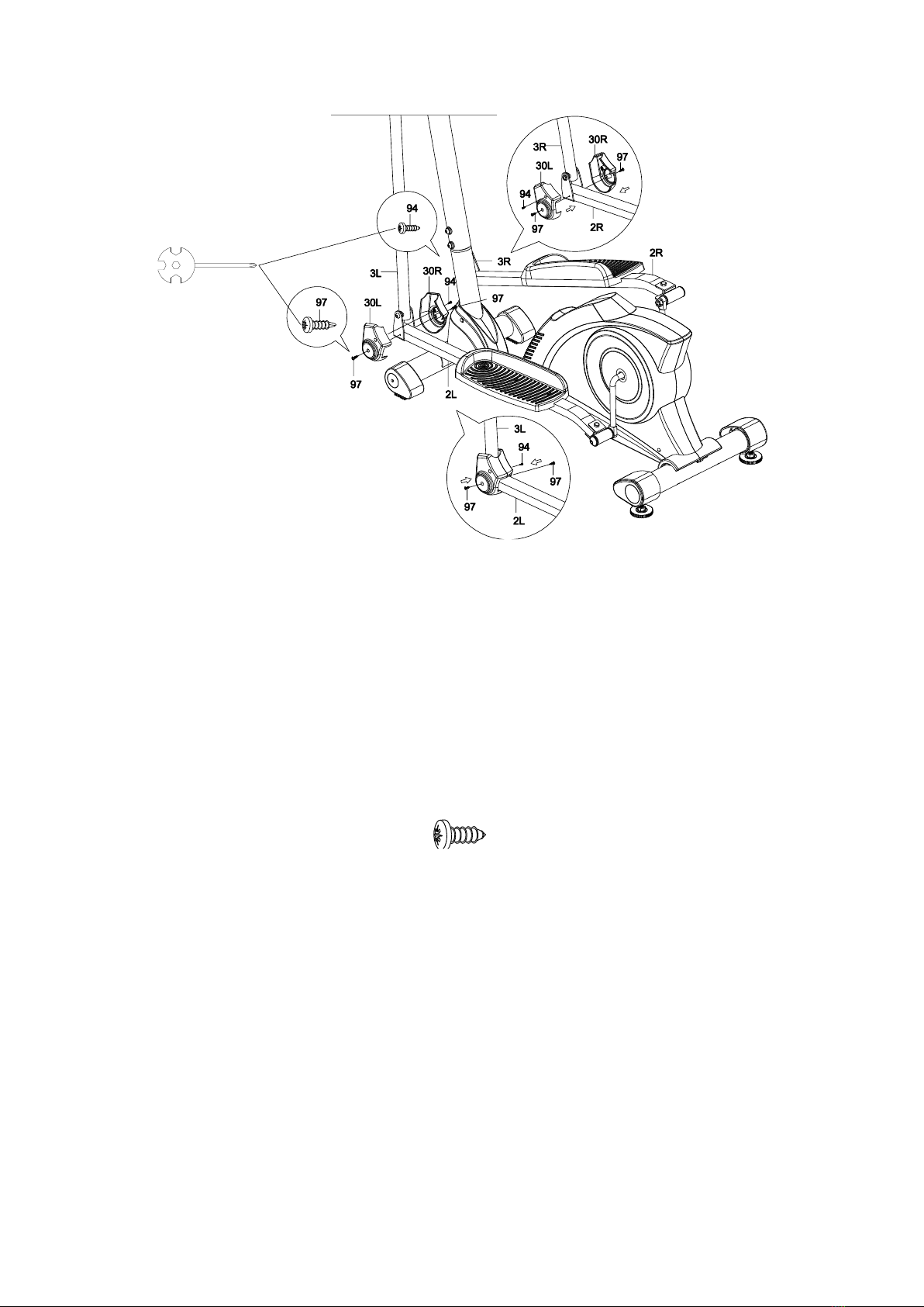
STEP 14
Remove four Cross Recessed Pan Head Drilling Screws with Tapping Screw Thread (97)
from the front end of the Left and Right Foot Bars (2L, 2R). Remove screws with the Multi
Hex Tool with Phillips Screwdriver provided.
Attach two Foot Bar Covers-A(30L) and two Foot Bar Covers-B (30R) onto the front end of
the Left and Right Foot Bars (2L, 2R) with two Cross Recessed Pan Head Tapping Screws
(94) and four Cross Recessed Pan Head Drilling Screws with Tapping Screw Thread (97)
that were removed. Tighten screws with the Multi Hex Tool with Phillips Screwdriver
provided.
Hardware:
(94) Cross Recessed Pan
Head Tapping Screw
2 PCS

18
STEP 15
Attach both Right and Left Handrails (4R, 4L) into the top ends of both Right and Left
Handrail Arms (3R, 3L) with four Carriage Bolts (44), four Curve Washers (45), and four
Nylon Nuts (24). Tighten nylon nuts with the Multi Hex Tool Phillips Screwdriver provided.
Hardware:
(24) Nylon Nut 4 PCS
(44) Carriage Bolt 4 PCS
(45) Curve Washer 4 PCS

19
STEP 16
Attach the Front Decorative Cover for Front Post (90) and Rear Decorative Cover for Front
Post (54) onto the Front Post (5) with two Cross Recessed Pan Head Tapping Screws (94).
Tighten screws with the Multi Hex Tool with Phillips Screwdriver provided.
Hardware:
(94) Cross Recessed Pan
Head Tapping Screw
2 PCS
This manual suits for next models
1
Table of contents
Other SPARTAN sport Elliptical Trainer manuals


