Bodytastic TurboSpin 96RV User manual
IC Bikes
TurboSpin®96RV
Owner’ s Manual
V.1.0 2016/03/09


1
Owner’s Manual
INTRODUCTION
Thanks you for choosing our TurboSpn® IC bike. You have just become our valued
customer. Our team will offer you detailed product information, expert cycling
advice, and customer support.
Our Bike is designed to closely simulate the feel of outdoor cycling. Its unique
design, with fixed gear and high inertia flywheel, provide anintense work out. You
cancycle at higher RPM and Cadences and by adjusting resistance level, develop
cardiovascular, muscle strength, concentration and balance training.
It should be enable to Improve cardiovascular function
Increase muscle strength, explosive
Increase lower body muscle exercise and bodysculpture.
Increase energy level
Whether the basis of physical training for beginners, advanced cyclists, or
commuters weight decrease, as long as 30 minutes daily and continuous, and at
any time to add water, youcan easily have a vitalityand good body
The owner's Manual contains all the information for you to operate and enjoy your
IC bike. Please read the Owner’s Manual carefully and entirely before start using
and getting onto the bike

2
Owner’s Manual
IMPORTANT SAFETY WARNINGS
Read and understand the complete Owner’s Manual
and Warnings before using the exercise equipment
Use this equipment only for its intended use as described in this manual. Do
not attempt to ride this bike at high pedal speed or in a standing position until
you have practiced and are comfortable riding at slower pedal speed.
This unit is NOTequipped witha freewheelsystem. Ifthe flywheel is in motion,
the pedals will be in motion. Do not attempt to stop the unit by applying
reverse pressure to the pedals as knee injury may occur. If you do need to
stop the equipment immediately, push down the resistance knob.
Do not attempt to remove your feet from the pedals while theyare in motionas
serious injury mayoccur from the pedals.
Do not dismount the equipment until the Flywheel and Pedal have completely
stopped.
In a home setting, keep the childrenaway from the equipment either in use or
not in use.
Do not try to use your hand or place fingers to turn or into moving parts of
equipment as the injurycould occur.
This symbol appearing throughout this manual means:
Attention!Be Alert! Your safety is involved.
.
The definition of WARINGS means that call attention to the potential
hazard which, if not avoided, could result in loss of life, serious injury

3
Owner’s Manual
IMPORTANT SAFETY WARNINGS
Warn the bystander to keep a safe distance at least 1 meter. It is not allowed
to touch the operator while the equipmentis in use.
To stay hydrated,drink water throughout your ride as needed.
Do not use the equipment with bare feet. Choose the proper footwear to
protect your feet.
The Maximum user weight limit: 160KG (350lbs). Do not use the equipmentif
youare over this weight limit.
Allow for at least 0.5 meters of free space to each side of the unit. This is
recommended safe distance for access or emergency dismounts from the
equipment.
Do not exert yourself. If you feel dizzy or any difficulty breathing, gradually
stop pedaling and carefully dismount the equipment.
Do not try to ride the bike at high speed in a standing position.
Follow the assemblyinstruction forsafety use the equipment, including proper
seat position, handlebar position. Never adjust the handlebar and seat in
height, seat fore-and-after past the minimum safe insertiondepth marked with
the word “STOP”.
Inoperable components should be replaced immediately or the equipment
should not be used until it is repaired. Contact customer service for repair
information and use genuine replacement parts.

4
Owner’s Manual
FEATURES
Magnetic Brake provides consistent, maintenance-free resistance that won't
wear or change over time
Aluminum construction on handlebar stem/seat post offers maximum stability
and durability.
Position number are permanently on the vertical post and horiztonal sliding
allowing user to set the comfortable position and replicate nextime.
Infinite horiztonal adjsutment allows to suit for more user.
Stailess Adjustment Handle are designed for corrosion resistance and can be
quickly threaded tight for a secure hold.
Frame is completelyED(electro depositioncoating)prior to the appliicationof
powder coating finish for corrosion resistance.
Stainless steel fasteners throughout aslo resist corrosion.
Enclosed chain guard keeps lubricated parts away from the rider, yet offers
convenient access for easy lubrication.
Easy to adjust the resitance by turning knob. Pushing down the knob will stop
the flywheel and pedal rotation.
Robust water bottle holder.

5
Owner’s Manual
PRODUCT SPECIFICATIONS
Dimensions 59” L x 19.9” W x48.4” H
(150cm x50.5cm x123cm)
Assembled Unit Weight 112 lbs(51 kg)
Packaged weight 123 lbs(56 kg)
Maximum User Weight Limit 160 kg(350 lbs)

6
Owner’s Manual
SAFETY WARNING LABELS
Before using the Equipment, Please find and read all the safety-warning labels.
Replace any damaged or illegible or missing labels. You can contact customer
support service if you need to replace the labels
Label 1 : Chain Warning Label
Location: Inside the chainguard
Label1

7
Owner’s Manual
Parts list
No. Description Q’ty Figure
1 Front Stabilizer 1
2 Rear Stabilizer 1
2-1 Hex Nut 2
2-2 Foot Leveler 2
3 Socket HexScrew
M8x1.25x55LSUS304 4
4 Flat washer
M8(φ19xφ8.5x1t) 12
5 Nylon Nut
M8x1.25(SUS304) 4
6 Pedal 1
7 Adjustment Handle 1
8 Non-Adjustable
Handlebar 1

8
Owner’s Manual
Parts list
No. Description Q’ty Figure
9 Handleabr post 1
10 Socket HexScrew
M8x1.25x12L 4
11 Socket HexScrew
M6*1.0*15L 2
12 Water Bottle Holder 1
13 Flat washer
M6(φ16xφ6.5x1t) 2
A Wrench
M22*3t*107L 1
B L- Hex Wrench
6mm/35Lx95L 1
C L-HexWrench
4mm/60Lx25L 1
D L-Hex Wrench
5mm/125Lx30L 1
E CombinationWrench
13/17mm 1
9
Owner’s Manual
Assembly
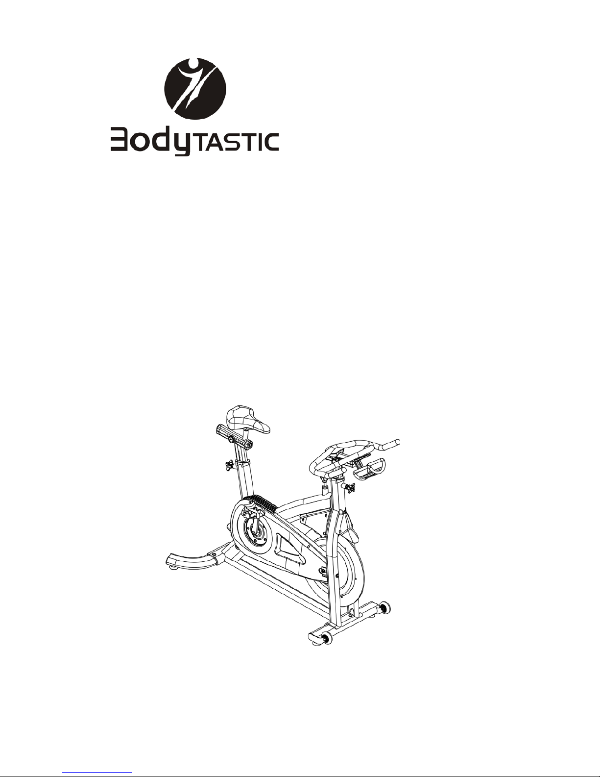
Front Stabilizer Assembly
1. Position the front stabilizer(1)on the frame
bracket as showed in the figure. Make sure the
transport wheel are facing up and toward the
front of the bike.
2. Attach the stabilizer withtwo hexscrews (3), four
flat washers(4)and two nylon nuts(5). Do not
over tightened as the deformation of stabilizer
may occur.
3. Make sure the leveling feet with nut are fullly
screwed into the stabilizer
Rear Stabilizer Assembly
1. Assemble the Foot leveler(2-2)and Hext Nut
(2-1)onto the Rear Stabilizer(2)
2. Position the Rear stabilizer(2)on the frame
bracket as showed in the figure.
3. Attach the stabilizer withtwo hexscrews(3), four
flat washers(4)and two nylon nuts(5). Do not
over tightened as the deformation of stabilizer
may occur.
4. Make sure the leveling feet with nut are fullly
screwed into the stabilizer
10
Owner’s Manual
Assembly
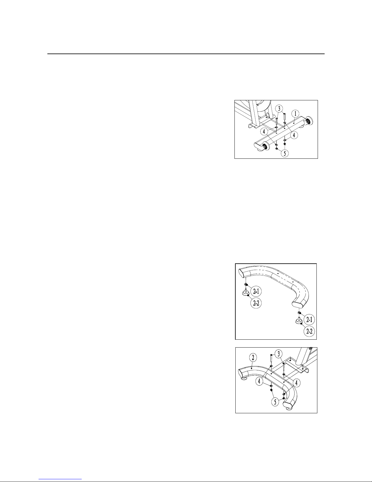
Pedal Assembly
1. Remove pedals from the components box.
2. Look at the end of the pedal axle and will notice the
eachpedal is marked with an Rand Lon the spindle.
It is indicated whichside of bike the pedal is intended
to assemble.
3. Locate the pedal marked the R on the spindle on the
right side of crank (Chainguard side). Turn clockwise
to tighten firmly. If possibile , apply some grease to
the threads before engae to the crank.
4. Locate the pedal marked the L on the spindle on the
Left side of crank (Chain guard side). Turn
counter-clockwise to tighten firmly. If possibile , apply
some grease to the threads before engae to the
crank.
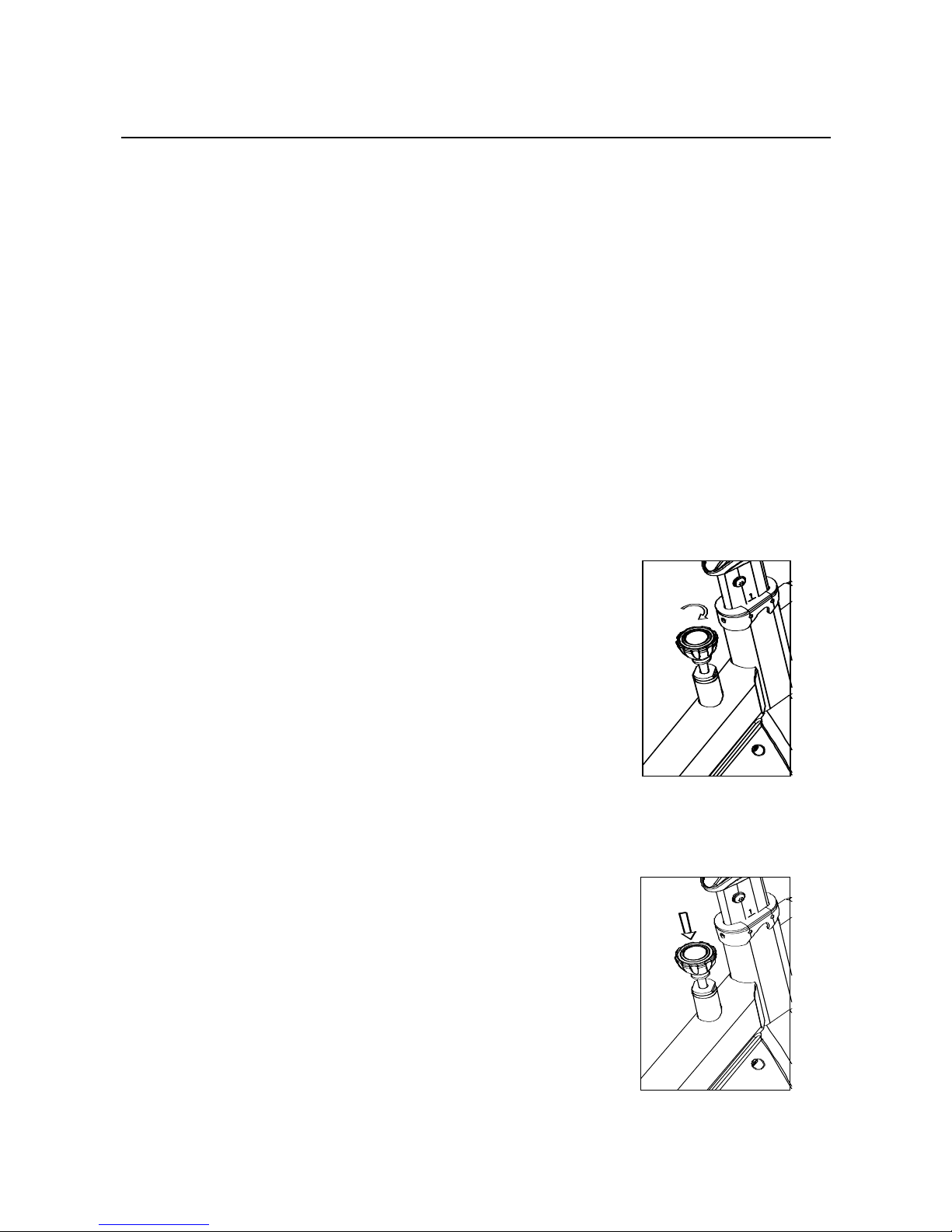
Adjustment Handle Assembly
Remove theAdjustmetnHadnle(7)from the components
boxand turnclockwise to tighten firmlyinto the frame
with wrench (A).
11
Owner’s Manual
Assembly
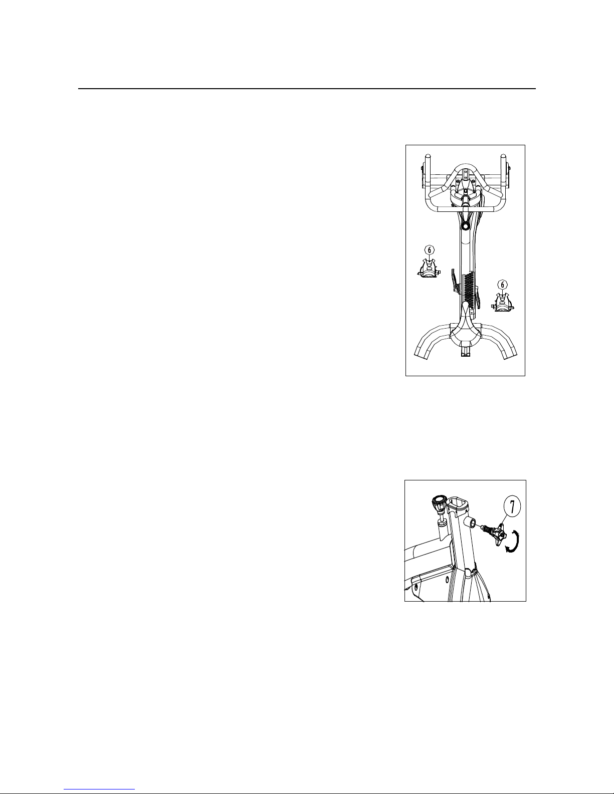
Handlebar Assembly
1. Assemble the Handlebar(8)
on to Handlebar post(9)with
four socket hexscrews(10)
and four flat washers(4).
2. Insert the Handlebar Assembly
into the frame tube and tightened
firmly withAdjustment Handle.
Water Bottle Holder Assembly
Assemble the Bottle Holder(12)with two socket hex
screws(11)and two flat washer(13).

12
Owner’s Manual
1
2
Assembly
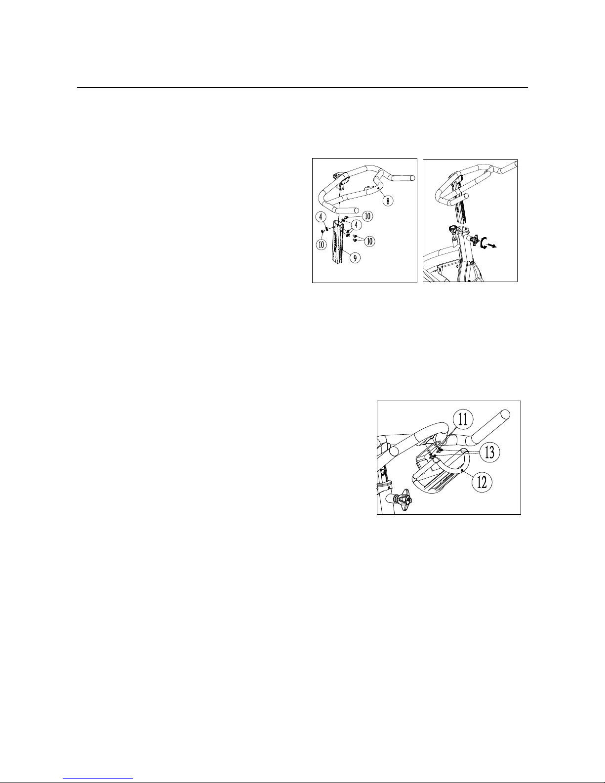
If equipped with Horiztonal adjustable Handlebar, please follow the below assembly
instruction
Part List
No. Description Q’ty Figure
8 Horiztonal adjustable
Handlebar 1
9 Upper Horiztonal
Adjustable Bracket 1
10 Socket HexScrew 2
11 Seat Post 1
Step.
1. Assemble the Upper Horizontal adjustable Bracket (9)andAdjustable
Handlebar(8)with two socket Hex screws(10)
2. Pull out the safety Pin(2)and slide the Handlebar onto the seat post(11).
3. Insert the Handlebar Assemblyinto the frame tube and tightened firmly with
T-pop pin

13
Owner’s Manual
HOW TO USE
Our indoor cycling is easy to use. The bike allows user to full control the levels of
resistance by simply adjusting the Resistance knob. You can choose the lower
resistance, which enable you to pedal at faster pace, or the higher resistance at
lower RPMs (Resolutionper minutes). Higher resistance levels will typicallydeliver
a greater muscle strength/endurance workout at lower RPMs.
This section instruct you howto use,including seat adjustment, Handlebar
adjustment, Resistance adjustment, Emergencybrake, Pedal strap adjustment,
Dismounting the bike, Moving the bike, Leveling the bike.
Seat adjustment
Proper seat height helps to ensure the maximum exercise efficiency and
comfort, while reducing the risk of Injury. Adjusting the seat
forward-and-backward allows working different lower bodymuscle groups.
Seat Heightadjustment
Do not raise the seat height above the STOP mark.
1. Turn
1. Turn the seat height Handle counterclockwise and pull it out to release it
from preset location. Raise and lower the seat post to the desire height.
Then release the Handle gently until it engages a preset hole on post. Be
sure to tighten the knob firmlyby clockwise.
2. Rotate the crank so that the pedals are at 12 and 6 o’clock position.
3. Place your foot in the toe cage of the pedal closest to the floor and mount
the bike. Ensure that the ball of your foot is over the center of the pedal. If
your leg is too straight or your foot cannot touch the pedal you will need to
lower the seat. If your leg is bent too much you will need to raise the seat
4. If necessary, you will need to try several seat height to reset the height for
most comfortable position. Repeat the instruction of the step 1 & 2 & 3 until
the seat is in the desired position.
5. Note the final position numberon the seat post for future reference.

14
Owner’s Manual
HOW TO USE
Seat forward-and-backward adjustment
1. Once the seat is in the desired position, dismount the bike and adjust the
seat forward-and-backward position.
2. Loosen the knob under the seat slider by turning counterclockwise. Slide
the seat forward and backward to the desire position.
3. When the seat is in the desired position, turn the knob clockwise to firmly
tighten the knob.
4. If necessary, you will need to try several seat height to reset the height for
most comfortable position. Repeat the instruction of the step2 until the seat
is inthe desired position.
5. Note the final position numberon the seat slider for future reference.
Handlebar adjustment
Proper Handlebar height helps to ensure the maximum exercise efficiency and
comfort. Handlebar height is a matter of preference. Adjusting the handlebars
higher will give the rider a more upright position; lowering them will result in a
more prone position. The handlebar should be adjusted to more accuratelyif you
feel discomfort in your back.
Handlebar Height adjustment
Do not raise the handlebar height above the STOP mark.
1. Start and positionthe handlebar at the same height as the seat. Thenmount
the bike to feel if it is in the desired position.
2. Turn the handlebar height handle counterclockwise and pull it out to release
it from preset location. Raise and lower the handlebar post to the desire
height. Thenrelease the handle gently untilit engages a preset hole onpost.
Be sure to tighten the knob firmlyby clockwise.
3. If necessary, you will need to try several positions to reset for most
comfortable position. Repeat the instruction of the step 1 & 2 until the
handlebar is in the desired position.
4. Note the final position numberon the handlebar post for future reference.
15
Owner’s Manual
HOW TO USE
Handlebar forward-and-backward adjustment
1. Once the Handlebar is in the desired position, dismount the bike and adjust
the handlebar forward-and-backward position.
2. Loosen the knob under the handlebar slider by turning counterclockwise.
Slide the handlebar forward and backward to the desire position.
3. When the handlebar is in the desired position, turn the knob clockwise to
firmly tighten the knob.
4. If necessary, you will need to try several positions to reset for most
comfortable position. Repeat the instruction of the step 2 & 3 until the
handlebar is in the desired position.
5. Note the final position numberon the seat slider for future reference.
Resistance adjustment
Resistance canbe adjusted easilyat anytime
while riding to change the intensity of workout.
Turn the knob clockwise (+) to increase
resistance. Turn the knob counterclockwise (-)
to decrease resistance.
Emergency brake
In case of emergency or before dismounting
the indoor cycle, presses directly DOWN the
resistance knob to stop the flywheel and
pedal.

16
Owner’s Manual
HOW TO USE
Pedal strap adjustment
Place the ball of you feet in the toe clip till the front of the shoe snugly in the
cage. Then tighten the strap of toe clip around your shoe by pulling up on the
strap until cage of toe clip fits snugly around the shoe.
Leveling the bike
Adjust the four leveling feet located on the underside of the frontand rear
stabilizer,raise or lower by using an adjustable wrenchto compensate for
unevenfloor surfaces.
Dismounting the bike
WARNING:
Our IC bike features with fixed gear so the flywheel momentum will
keep the pedal rotating even after user stop pedaling or even the feet
slip off the pedal incautiously. Do not attempt to dismount or move
you feet out of pedal until both the flywheel and the pedal have
stopped completely. Failure to follow may lead to loss of control and
serious injury.
Here are some correct wayto stop the pedal and flywheel to dismount the bike
1. Lower the pedal speed until the pedal completely stop.
2. Increase the resistance until the pedal completely stop.
3. Push down the resistance knob for Emergency brake function until the
pedalcompletely stop.

17
Owner’s Manual
HOW TO USE
Moving the bike
1. Make sure the handlebar post and Seat post
is securely by tightening the pop-pin
clockwise.
2. Standing in the from of Bike and clasp the
end of handlebar.
3. Place one foot on the lower stabilizer and tilt
the bike towards you until the bike is titled
enough to allow the transport wheel to touch
the ground. Then you can easily roll the bike
in any direction. Be gentle while moving the
bike as many unexpected impact may affect
the operation of bike.

18
Owner’s Manual
MAINTENANCE
Chain Tension adjustment
The chain tension had been set and lubricated before shipped. It should not
need to be adjusted when first using. However, you may need to make the
minor tension adjustmentover time.
Note: Make sure you adjust both side equally, either tighten or loosen the
chain tension so that the flywheel keep in alignment with the frame
Tighten the Chain tension
Move the crank arms back and forth. If there is more than 1/4” (0.64cm)
movement in the crank before flywheel starts turning, you will need to adjust
the chain.
1. Loosen the two-flanged nut(A) on either side of
flywheel.
2. Moving the flywheel forward by evenly tightening
clockwise the 2 hex bolts(B), which go through the
frame tube until there is approximately1/4” (0.64cm)
of slack in the chain.
3. Re-tighten the two-flanged nut on either side of
flywheel and then put back the safety cover.
Loosen the Chain tension
1. Normally the rider will feel the strong vibration in the lower RPMs
(20-50RPMs) if the chain is too tight. If this happened, you will need to
adjust the chain.
2. Loosenthe two-flanged nut on either side of flywheel.
3. Moving the flywheel backward by evenly loosening counterclockwise the
2 Hexbolts which go through the frame tube. Suggest turning 1/2 turn.
4. Re-tighten the 2 flanged nut oneither side of flywheel and then put back
the safety cover
5. You will need to repeat the step if you still feel vibration after adjustment
A
B
Table of contents
Other Bodytastic Exercise Bike manuals


Popular Exercise Bike manuals by other brands


Argos
Argos Opti Assembly & user instructions

Christopeit Sport
Christopeit Sport BT 4 Assembly and exercise instructions

Weslo
Weslo Pursuit S 25 Exercise Bike Manual Del Usuario

Vermeiren
Vermeiren Kim user manual

Elite Fitness
Elite Fitness Destroyer Assembly manual

BH FITNESS
BH FITNESS YF90 Instructions for assembly and use


