Elite Fitness Destroyer User manual

ASSEMBLY MANUAL
Record serial number
Elite Destroyer Exercycle

2
CONTENTS
Important Safety Instrucons 3
Product Specicaons 4
Hardware List 5
Assembly Conponents 6
Assembly Instrucons 8
User Instrucons 17
Computer 18
Seat Adjustment 23
Care and Maintenance 24
Maintenance Log 25
Limited Warranty 26
Warm-Up Exercise 27
Training Stages 28
Parts 29
Exploded Drawing 31
Notes 33
Thank you for purchasing the Elite Destroyer.
For over 20 years, Elite Fitness™ has been New Zealand’s largest supplier of tness equipment. Our
aim and vision is to provide you Elite™ branded products, tested to the highest standard for quality
and biomechanics at the best possible price.
Please read through this manual to familiarise yourself with the operaon of your new Elite
Destroyer. Doing so will help to ensure that you get the most out of your machine, enjoying safe
and eecve workouts ahead.
Even though we go to great eorts to ensure the quality of each product we produce, occasional
errors and or omissions do occur. In any event should you nd this product to have either a
defecve or a missing part, please contact us for a replacement.
SERVICE & WARRANTY
For service and warranty assistance please visit:
www.elitetness.co.nz/service
Online forms are available for Service, Warranty and Parts requests.
(09) 258 9067
Elite Fitness HQ
11 George Bourke Drive
Mt Wellington
Auckland, New Zealand
info@elitetness.co.nz
0800 2 438 348
www.elitetness.co.nz

3ELITE EXERCYCLE ASSEMBLY MANUAL
The following denion applied to the word “WARNING” when used in this manual:
Used to call aenon to POTENTIAL hazards that could result in
personal injury.
READ ALL INSTRUCTIONS BEFORE USING THE MACHINE
This product has been designed for home use only. Product liability and warranty condions will
not be applicable to products being subjected to professional use or products being used in a
commercial environment. e.g Gym Centre, Rerement Centre, Home Based PT Studio and Physio.
This exercise machine is built for opmum safety. However, certain precauons apply whenever
you operate a piece of exercise equipment. Be sure to read the enre manual before you assemble
or operate your machine. In parcular, note the following safety precauons.
— Read all instrucons in this manual before using this equipment.
— Use the machine only for its intended use as described in this Manual.
— Inspect and ghten all the loose parts before this equipment is used.
— Keep hands away from moving parts.
— Keep children and pets away from the machine at all mes. DO NOT leave children unaended
in the same room with the machine.
— Before using the machine to exercise, always do stretching exercises to properly warm up.
— Inspect the machine before each use; make sure all of the connecons are ghtly secured.
— Only one person at a me should use the machine.
— If the user experiences dizziness, nausea, chest pain, or any other abnormal symptoms, STOP
the workout at once. CONSULT A PHYSICIAN IMMEDIATELY.
— Posion the machine on a clear, levelled surface. DO NOT use the machine near water
or outdoors.
— Always wear appropriate workout clothing when exercising. DO NOT wear robes or other
clothing that could become caught in the machine. Sporng shoes are recommended when
using the machine.
— Do not place any sharp object around the machine.
— Disabled persons should not use the machine without a qualied person or physician
in aendance.
— Never operate the machine if the machine is not funconing properly.
— Only carry out training work on the equipment when it is in perfect working order. Only use
original spare parts in the event of a repair.
— Do not use strong solvents for cleaning, and only use the tools supplied, or suitable ones of
your own, for any repairs that may be required. Please dispose of the packaging and any parts
that have to be replaced subsequently (all parts for the unit) at suitable collecng points or
containers with a view to saving the environment.
— DO NOT extend the seat stem past the warning line “Max” when adjusng the seat height.
— Not for therapeuc use.
IMPORTANT SAFETY INSTRUCTIONS
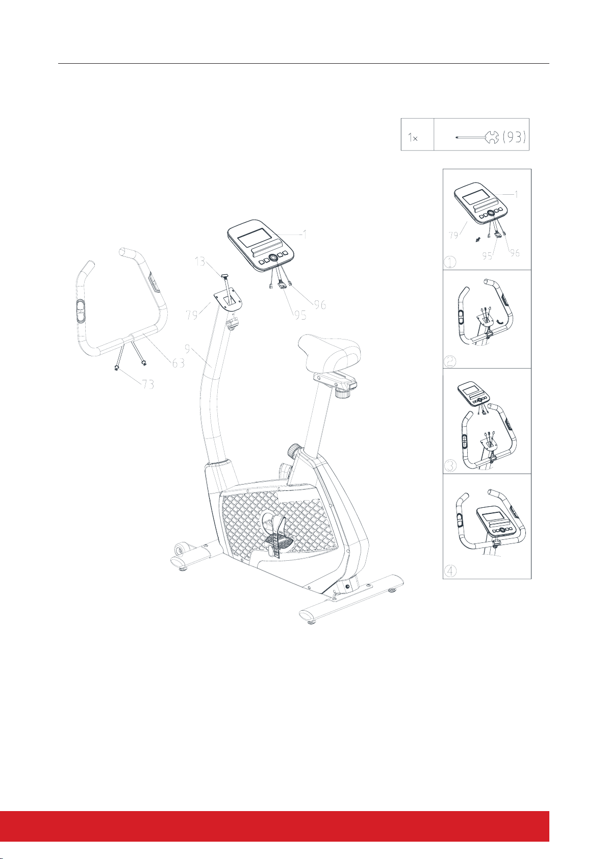
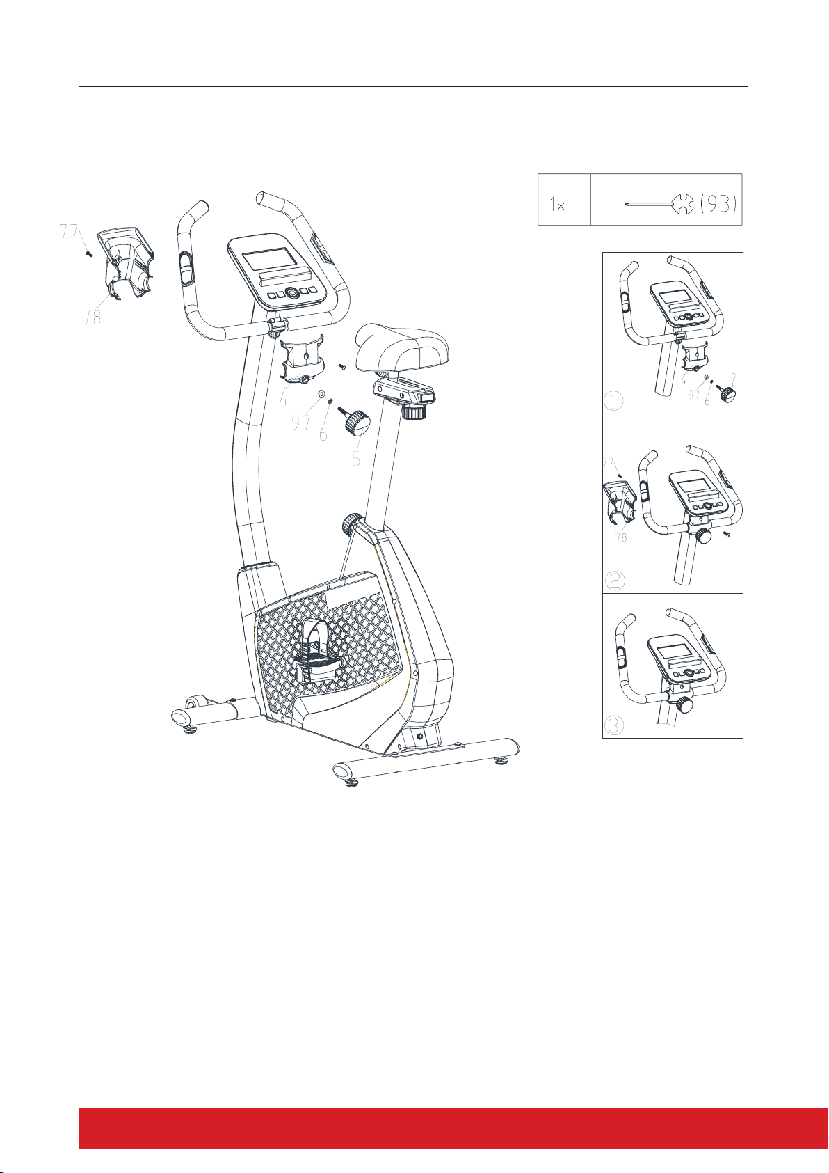
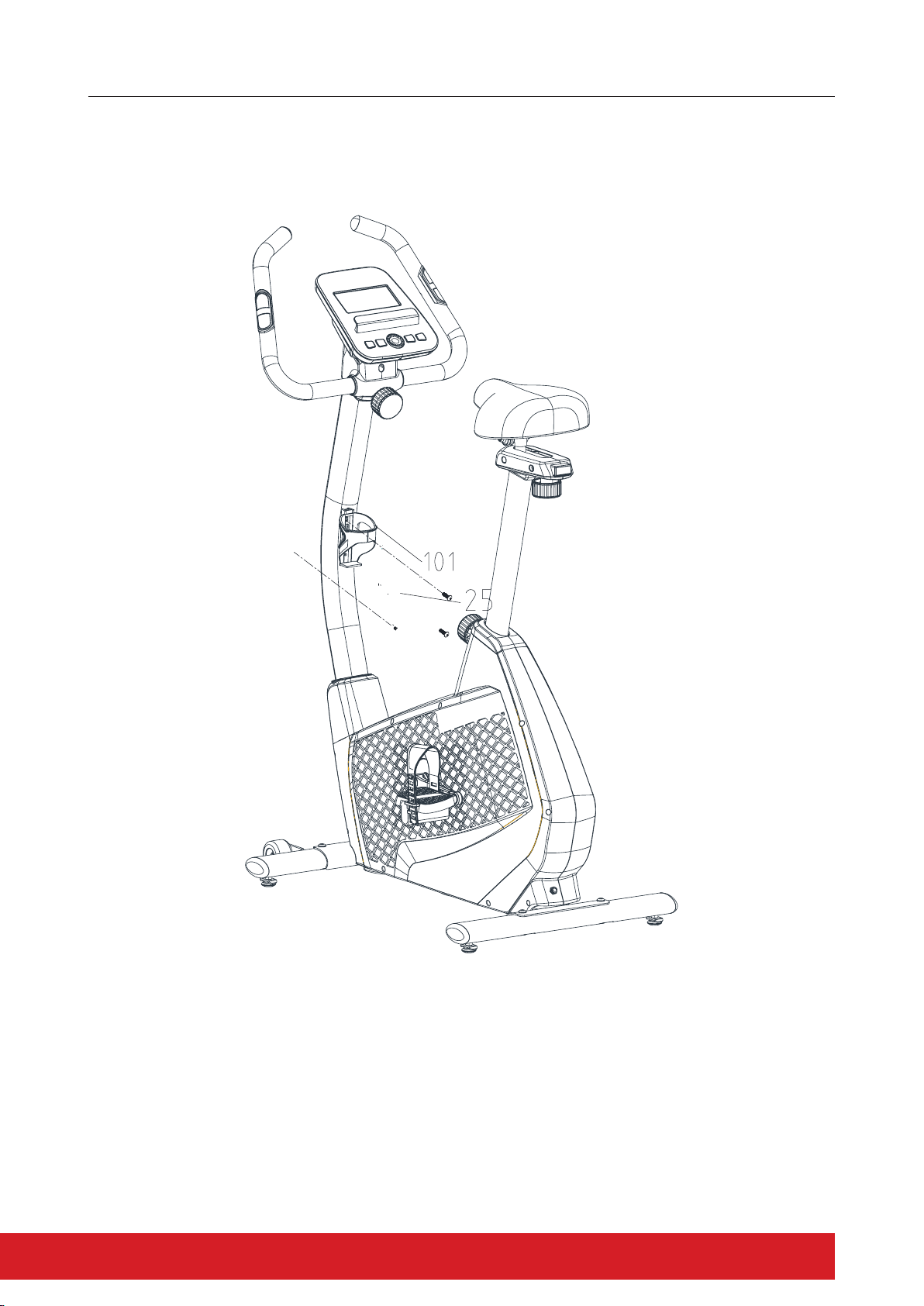
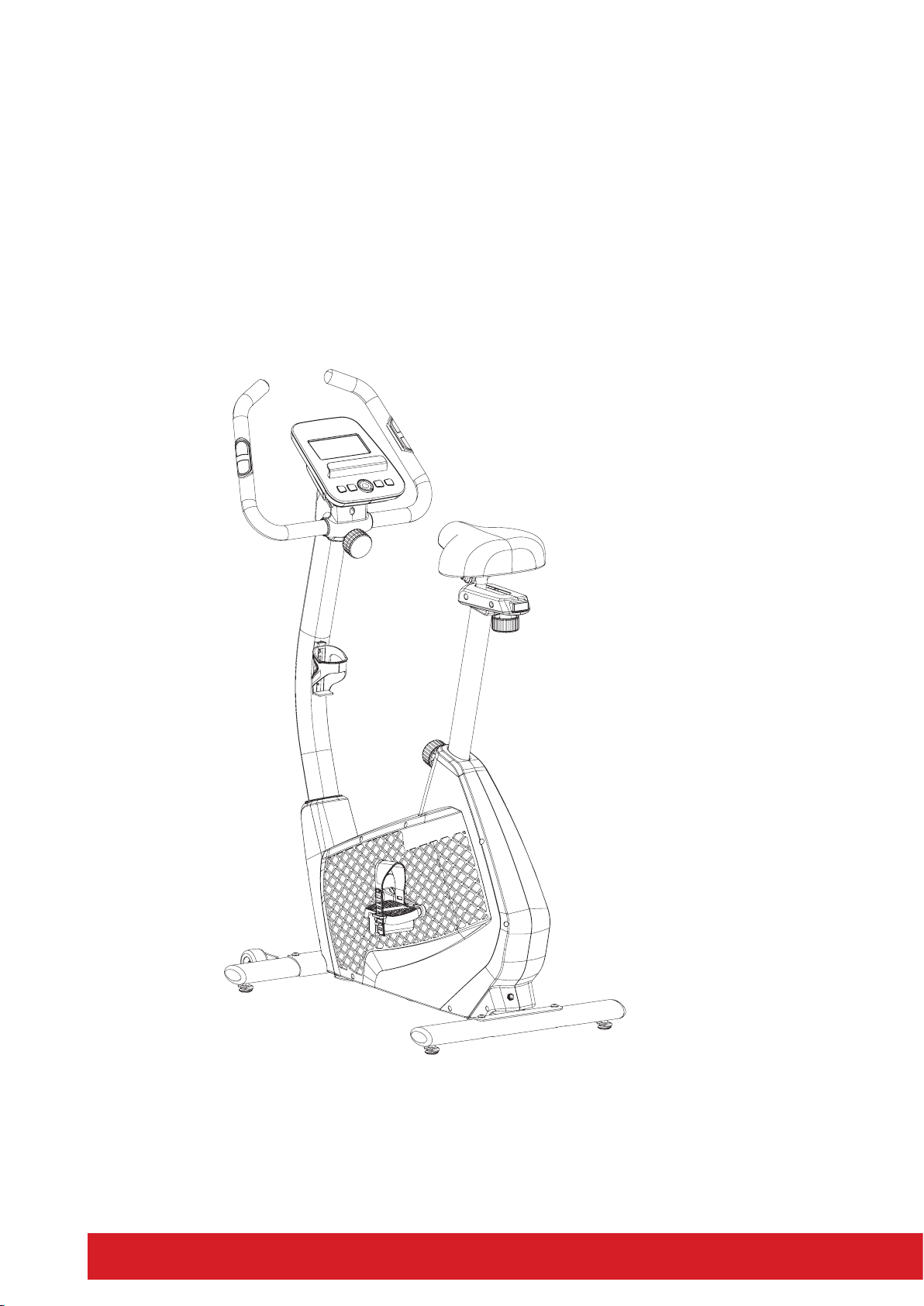
4
WARNING: Before beginning any exercise programme, consult your physician. This is especially
important for persons with pre-exisng health problems. The seller assumes no responsibility for
personal injury or property damage sustained by or through the use of this product.
SERVICE HINTS: The high quality standard of this product only will be kept if you, on a regular
basis, check all screw connecons and moving parts on proper ng. Damaged parts need to be
changed immediately. During the me of repair the product must not be used by anybody.
IMPORTANT HINTS:
A) This product has been tested in accordance with the requirements of EN 957-1/A1, EN 957-5,
standard, Class HA (HOME USE). The maximum load is limited to 120KGS.
B) Parents should be aware of the risk factor of young children playing on tness equipment
unaended. Make sure that children are instructed properly in the use of the product and in
the controlled execuon of the dierent exercises. Misuse of the product could result in
serious injury.
PRODUCT SPECIFICATIONS
User Weight Capacity: 120kg
Dimensions: 1185 x 540 x 1390mm
Shipping Weight: 42kg
Net Weight: 38kg
Power Requirements 6V 1.0A

5ELITE EXERCYCLE ASSEMBLY MANUAL
HARDWARE LIST
Part No. Descripon Q’ty
5 Knob 1
6 Wave washer 1
97 Flat washer 1
57 semi-circle washer 4
58 Screw 4
93 The harpoon wrench 1
94 Hex spanner 1
98 Socket spanner 1

6
ASSEMBLY COMPONENTS
Tools Required For Assembling the Machine:
— One Crossing Wrench and Allen Wrench, provided by manufacturer.
NOTE: It is strongly recommended that two or more people assemble this machine to avoid
possible injury.

7ELITE EXERCYCLE ASSEMBLY MANUAL
Part No. Descripon Q’ty Part No. Descripon Q’ty
1 Computer 1 42 Pedal-R 1
4 Computer tray 1 56 Rear stabilizer 1
9 Handle tube 1 64 Frame 1
14 Handle tube cover 1 99 Front stabilizer 1
20 Seat tube 1 63 handlebar 1
25 Seat 1 78 Computer tray 1
101 Bole cage 1 84 Cover 1

8
ASSEMBLY INSTRUCTIONS
Part No. Descripon Q’ty Part No. Descripon Q’ty
1 Computer 1 42 Pedal-R 1
4 Computer tray 1 56 Rear stabilizer 1
9 Handle tube 1 64 Frame 1
14 Handle tube cover 1 99 Front stabilizer 1
20 Seat tube 1 63 handlebar 1
25 Seat 1 78 Computer tray 1
101 Bole cage 1 84 Cover 1

9ELITE EXERCYCLE ASSEMBLY MANUAL
STEP 1
Do not ghten Bolts unl instructed to do so.
— Aach the Front Stabiliser (#99) to the Main Frame (#64). Secure it with 2 M8 Screws (#58) and
2 Semi-circle Washers (#57).
— Aach the Rear Stabiliser (#56) to the Main Frame (#64). Secure it with 2 M8 Screws (#58) and
2 Semi-circle Washers (#57).
—Securely ghten all Bolts.

10
ASSEMBLY INSTRUCTIONS
STEP 2
— Thread the Le Pedal (#80) counterclockwise into the le Crank Arm (#79).
— Thread the Right Pedal (#40) clockwise into the right Crank Arm (#39).

11ELITE EXERCYCLE ASSEMBLY MANUAL
ASSEMBLY INSTRUCTIONS
STEP 3
— Insert the Seat Post (#20) into the Main Frame (#64) and secure with the Pull Pin (#18).
The Pull Pin is used to adjust the height of the exercycle. Adjust to desired height. See Pic 1
— Place the Sliding Block (#24) and the Seat Slider Cover (#22/#27) over the Seat Post (#20) and
secure it in place using Locking Pin (#28).
— Aach the Seat (#25) to the Seat Post (#20). Adjust the lt accordingly for individual comfort.
Tighen the seat nuts securely

12
ASSEMBLY INSTRUCTIONS
STEP 4
— Connect the middle secon Sensor Wire (#13) of the Front Post (#9) and Front Cover (#14)
with the lower secon Sensor Wire (#7) securely. Put the Front Post (#9) and front cover (#14)
into the boom post of main frame (#64) and fasten with 4 x M8 Screw (#12),
4 x Flat Washers (#57) .

13ELITE EXERCYCLE ASSEMBLY MANUAL
ASSEMBLY INSTRUCTIONS
STEP 5
— Connect the Hand Rail (#63) to the Front Post (#9), ensure the Hand Pulse cables are routed
through the Front Post (#9)
— Aach the computer Hand pulse Wires to the Computer pulse connecon. See Pic 3 and 4
— Connect the Computer (#1) to the Front Post (#9) using 4 x M5 Screws
(Located in the console).

14
ASSEMBLY INSTRUCTIONS
STEP 6
— Secure the Plasc Cover (#4) over the Handle bar using the T-Shaped Knob (#5).
— Wave Washer (#6), Flat Washer (#97) and 1 x M5 Screw.
— Connect the Rear Handle Bar Cover (#78) to the back of the Computer and Front Post using 2 x
Screws (#77).

15ELITE EXERCYCLE ASSEMBLY MANUAL
ASSEMBLY INSTRUCTIONS
STEP 7
— Aach the Water bole holder (#99) to the Front Post (#9) using 2 x Screws (#25).

16
CONGRATULATIONS
Assembly of your Elite Destroyer Exercycle is now complete! Be sure to fully inspect your machine
before using it for the rst me.
WARNING: Failure to visually check and test the assembly of your exercycle before use can cause
damage to the exercycle and injury.

17ELITE EXERCYCLE ASSEMBLY MANUAL
SEAT ADJUSTMENT
Having your bike seat adjusted to the right height is essenal for a comfortable ride, ecient
pedalling and avoiding injury. There are 2 adjustments located on the seat post. The rst is a
vercal height adjustment, the second is for horizontal seat posion. Although there are many
methods and opinions on the opmal saddle seng, the following is a quick and easy method to
get started. Further adjustments can be made aerwards to opmise your posion and comfort.
Saddle Height Adjustment
Place your heels on the bike pedals and pedal backward. Your legs should be fully extended with
your knees straight. If your hips rock from side to side while pedalling backward, the seat is too
high. Place the ball of your foot on the pedal. There should now be a slight bend in your knee
when the pedal is at its lowest point. This is a good starng point. Refer to examples below.
Seat Adjustment
Ensuring you have the most comfortable riding posion whilst minimising joint strain is important.
Adjusng your seat is simple and can normally be done without needing to get o the bike.
Place your heel on one of the bike pedals and rotate to the furthest point on the pedal stroke (as
shown) You may need to remove the toe strap to do this. If the leg is sll in the bent posion, unlock
the seat mechanism and adjust to the fully extended posion (Pic.1) – Lock the seat adjustment
mechanism in to place.
Moving your foot backwards, place your forefoot on to the pedal in the correct riding posion.
This should allow for a natural bend in the knee, whilst providing a full 360 degree rotaon. If you
experience the feeling of reaching for the pedal or sliding down the seat, you may need to make a
minor adjustment to the posion. Before commencing your workout please reaach and adjust the
toe strap correctly to secure your foot rmly on the pedal.”
Note: - If you are using the exercycle for injury rehabilitaon purposes i.e. Knee Replacements you may need to extend the
seat posion further than normal to allow for any reduced joint mobility due to swelling and inammaon
— Whilst sing on the seat, bring your le crank arm around and have your helper stop the crank when the pedal is at
three o’clock or parallel with the oor. For this measurement to be accurate, your shoes must be correctly posioned
on the pedals (the balls of your feet should be over the pedal axles).
— Holding this posion, have your helper place the end of the plumb line on the front of your leg, at a point just below
the bony protrusion beneath the kneecap.
— The plumb line’s weight should hang over your shoe. Check again to ensure that the crank-arm and pedal are level.
By looking at the plumb line the knee should be in alignment with the centre spindle or axle of the pedal.
— Adjust the saddle to the correct posion then ghten the locking pin.
Pic 1 Pic 2

18
USER INSTRUCTIONS
SCAN : Alternates between WATTS/CALORIES and RPM/SPEED. 6 seconds per display.
RPM : 0 -15-999
SPEED : 0.0-99.9 km/h
TIME : 0:00-99:59.
DISTANCE : 0.00-99.99 km
CALORIES : 0-999.
WATTS CONSTANT :10-350
HEART SYMBOL : ON / OFF ashes
MANUAL : 1-24 level
PROGRAM : P1-P12
USER DATA
CONTROL MODE
MANUAL / PROGRAM / WATT / PERSONAL / HRC
TIME
RPM/SPEED
RECOVERY
RESET
START/STOP
MODE
UP & DOWN
PULSE
WATTS/CALORIE
DISTANCE

19ELITE EXERCYCLE ASSEMBLY MANUAL
USER INSTRUCTIONS
PRE-SET USER:
Enter user data (sex / age/ height / weight) to accurately calculate workout feedback.
SELECT
MANUAL/PROGRAMS/ WATT CONSTANT/PERSONAL/FITNESS(OPTION)/H.R.C
User can choose dierent control modes to start their workout. See below is main descripon of
each control mode.
EXECUTE
MANUAL/PROGRAMS/ WATT CONSTANT/PERSONAL/ FITNESS(OPTION)/H.R.C
Execute selected control mode.
PRE-SET
TIME/DISTANCE/CALORIES/WATTS/HEART RATE
Seng and selecng the users desired funcon value of the above, the funcon value display will
count down to zero; or if the user does not input any funcon value, the computer will know your
workout is from 0 to end value.
PRESS ENTER/UP/DOWN/START/PAUSE
Use UP / DOWN key to increase / decrease funcon value.
Aer seng each funcon value to press “ENTER” to conrm your seng.
START / PAUSE- Finish previous seng step to press START to start operang; user can press
“PAUSE” if they want to pause their workout for a short peroid of me.
TEST RECOVERY
Press RECOVERY, the computer will calculate your recovery value and will display the results. This
uses your preset data and actual workout funcon value.
FUNCTION DESCRIPTION
— MANUAL: Set the resistance level using the dot matrix display then (if required) set exercise
parameters TIME/DISTANCE / CALORIES / PULSE then press START/STOP to START manual
program.
— PROGRAM: 12 automac adjusng programs with control exercise (P1~P12), resistance level
can be adjusted during PROGRAM DIAGRAM is ashing.
— WATTS CONSTANT: User can default WATTS value at their desire 10-350 was between 10~350
was by using the UP/ DOWN knob. To x WATTS constant value and then press ST/STOP key.
Use WATTS control mode to train yourself in dierent WATTS’s constant.
— PERSONAL: Create your own Program prole through U1~U4 by seng the resistance level
for each individual segment. Then the Program will be automacally saved for future use. U0
ENTER can be set the same as U1~U4 but this Program cannot be saved.
— FITNESS (OPTION): It is special workout program regarding with user’s gender and age to gauge
your exercise level F1- F5 during 12 minutes. User 1- User 4 choose FITNESS control mode
by UP/DOWN KEY, and then pres ST/STOP key, if user’s heart rate reach to 100% lasng 30
seconds, this mode funcon will be stoped. Aer nished this FITNESS funcon, please refer
below FITNESS table.

20
Note:
1.If the user reaches F1 level and their heart rate is not over H.R.C 100%, the computer/console
stop working.
2. If user can’t reach F5 level, and their heart rate is over H.R.C 100%, the computer / console stop
working.
3. If the user reaches level F1-F4, and their heart rate is not over H.R.C 100%, the computer will
stop aer 12 minutes and will display F1 level.
USER INSTRUCTIONS
LEVEL GENDER AGE < 30 AGE 30-39 AGE 40-49 AGE >50
MALE DISTANCE <3.2KM <3KM <2.8KM <2.6KM
F5 SPEED 16KM 15KM 14KM 13KM
FEMALE DISTANCE <3KM <2.8KM <2.4KM <2.2KM
SPEED 15KM 14KM 12KM 11KM
MALE DISTANCE 3.2-4KM 3-3.38KM 2.8-3.4KM 2.6-3.2KM
F4 SPEED 20KM 19KM 17KM 16KM
FEMAILE DISTANCE 3-3.6KM 2.8-3.4KM 2.4-3KM 2.2-2.8KM
SPEED 18KM 17KM 15KM 14KM
MALE DISTANCE 4-4.8KM 3.8-4.6KM 3.4-4.2KM 3.2-4KM
F3 SPEED 24KM 23KM 21KM 20KM
FEMAILE DISTANCE 3.6- 4.4KM 3.4-4KM 3-3.8KM 2.8-3.4KM
SPEED 22KM 20KM 19KM 17KM
MALE DISTANCE 4.8-5.6KM 4.6-5.4KM 4.2-5KM 4-4.8KM
F2 SPEED 28KM 27KM 25KM 24KM
FEMAILE DISTANCE 4.4-5.4KM 4-5KM 3.8-4.6KM 3.4-4.4KM
SPEED 27KM 25KM 23KM 22KM
MALE DISTANCE >5.6KM >5.4KM >5KM >4.8KM
F1 SPEED 28KM 27KM 25KM 24KM
FEMAILE DISTANCE >5.4KM >5KM >4.6KM >4.4KM
SPEED 27KM 25KM 23KM 22KM
Table of contents
Other Elite Fitness Exercise Bike manuals

Elite Fitness
Elite Fitness NERO User manual

Elite Fitness
Elite Fitness WAVE ROWER User manual

Elite Fitness
Elite Fitness RAZOR R9+ User manual

Elite Fitness
Elite Fitness Phantom User manual

Elite Fitness
Elite Fitness COLT User manual

Elite Fitness
Elite Fitness Slimline Series User manual

Elite Fitness
Elite Fitness FALCON User manual

Elite Fitness
Elite Fitness VAlOR 4 User manual

Elite Fitness
Elite Fitness DEFENDR User manual

Elite Fitness
Elite Fitness VO5 User manual