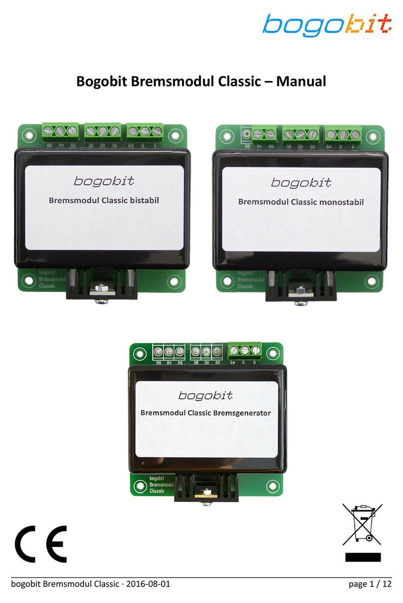
Bogobit Standard-Bremsmodul User manual

Bogobit Standard-Bremsmodul – Manual
bogobit Standard-Bremsmodul · 2016-08-01 Seite 1 / 7

1 Introduction
Please read the instructions completely be ore using the product. Observe all operating and sa ety
instructions!
All brand, product and company names used herein may be trademarks o their respective owners.
2 Intended Use
The Bogobit Standard-Bremsmodul is a brake module or digitally controlled model railways. The
module generates a “brake voltage”. This lets locos brake smoothly i they are equipped with a
suitable decoder. It can be used on model layouts with center stud tracks (Märklin H0). It can be
used on digitally controlled model railways using the Märklin/Motorola/m x protocol.
This product is no toy. It is not suitable or children up to 14 years o age.
Any use other than that described be ore is not permitted.
The product may not be modi ied or reassembled.
3 Safety Instructions
3.1 General
In case o damage incurred by disregarding these operating instructions, the warranty claim is void.
Liability or any and all consequential damage is excluded!
We do not assume any liability or damage to property or personal injury caused by improper use
or the ailure to observe the sa ety instructions! The warranty is voided in these cases.
•
For sa ety and licensing reasons (CE), it is not permitted to change or modi y the product.
Only use original or equivalent replacement parts or repair.
•
Ensure that all electrical connections and connection cables con orm to regulations and
comply with the operating instructions.
•
Upon sudden change o climatic conditions (e. g. trans er rom a cold place to a warm
room) water may condense on the device, which may lead to damage. Allow approx.
2 hours to acclimate be ore powering on the device.
•
Do not operate the device near easily in lammable objects, liquids or gases. Danger o ex-
plosion!
•
Do not expose the device to high temperatures, strong vibrations, high humidity or chemic-
ally aggressive environment.
•
Operate the device only in dry indoor rooms (below 80 % humidity, non condensing) and at
normal room temperature (0 °C to 40 °C).
•
Do not operate the device unattended.
•
When in doubt about sa ety, or the connection or operation o the device, which is not ex-
plained in these operating instructions, please contact us or a recognized expert.
bogobit Standard-Bremsmodul · 2016-08-01 Seite 2 / 7

3.2 Electrical Safety
•
Operate the module only with low voltage according to the speci ications in the technical
data chapter. Only use power supplies, such as trans ormers or digital control stations, that
are certi ied or use in model railway applications. Connection o higher voltages (e.g. 230 V
mains voltage) is not permitted, also not on relay contacts. There is danger to li e through
an electric shock and a risk o ire!
•
Adhere to the limits on maximum allowable current according to the speci ications in the
technical data chapter. Exceeding the limits leads to overload and destruction o the device
and bears the risk o ire or electric shock.
•
Switch o the power supply be ore working on the electrical connections.
•
Pay attention to appropriate wire cross sections (rule o thumb: 0,1 mm² per 1 A maximum
possible current, e. g. 0,5 mm² cross section or 5 A maximum current).
3.3 eat Generation
Electronic components on the product may heat up during operation.
•
When mounting the product, ensure su icient air circulation around the device to prevent
heat build-up and overheating. This especially applies when installing the board in a hous-
ing.
4 Function of the bogobit Bremsmodul
4.1 General Function
The Bogobit Bremsmodul Classic is a brake module or digitally controlled model railways. The
module generates a “brake voltage”. This brake voltage, when applied to the track, lets locos brake
smoothly i they are equipped with a suitable decoder. It can be used on model layouts with center
stud tracks (Märklin H0). It can be used on digitally controlled model railways using the Märklin/
Motorola/m x protocol.
The brake voltage is basically just negative DC voltage. This working principle is known to märklin
users as the “märklin brake module”. Locos with digital decoders or the Märklin/Motorola/m x
protocol brake, i the voltage on the center studs is not the digital voltage, but a dc voltage. The
polarity o the center studs is negative with respect to the rails. Some old or simple decoders, such
as Delta and 6080 decoders, may stop in the brake section abruptly, but the vast majority o mod-
ern decoders brake smoothly.
Thus, to brake a digital controlled loco smoothly, an isolated track section is required, whose cen-
ter studs are either connected to digital voltage (the “proceed” state), or to dc voltage (the “brake”
state). However, i dc voltage is applied, and a loco travels over the track isolation, the pickup shoe
will cause a short circuit between the digital voltage outside, and the dc voltage inside the brake
section. Such a short is avoided by additional track sections, a so-called transition track section be-
bogobit Standard-Bremsmodul · 2016-08-01 Seite 3 / 7

ore the brake section, and a stop section (or a transition track section alternatively) a ter the
brake section.
The Bogobit Standard-Bremsmodul has the ollowing eatures:
1. The brake module can be connected in parallel to a turnout or a signal (with double
solenoid drive).
2. In the proceed state, ull digital voltage is applied to all track sections. (no jerky drive on
the transition track).
3. The control inputs can be driven universally by AC or DC voltage o either polarity.
5 Connection and Operation
5.1 andling
The product consists o sensitive electronic components. Improper handling may destroy them.
Prior to handling the board, please discharge yoursel rom electrostatic charge. To do this, touch a
metal object (earthed), e.g. a metal PC casing. Try to touch the board only at the edges and avoid
touching any electronic components or copper routes on the board.
5.2 Mounting
Mount the module properly to the model railway ramework. The module has holes with 3 mm
diameter or mounting. Use o wood screws with 3 mm diameter and a lat pan head is recommen-
ded. Use spacers (little plastic tubes) between circuit board and mounting sur ace. Tighten the
screws care ully, so that the circuit board does not warp. Also consider the instructions related to
heat generation in chapter 3.3.
5.3 Electrical Connections
5.3.1 Wiring Terminals
The external connections o the brake module are labelled on the board and explained in the table
below:
Label Meaning Connection
0 0 to digital control station "0" / track rails
B B to digital control station "B" / track center studs
Ü# transition track to center studs o the isolated transition track section
B# brake track to center studs o the isolated brake track section
S* switch contact common i stop section required: connect to "B"
SG switch contact green i stop section required: connect to center studs o stop section
SR switch contact red i stop section required: no connection
R* relay common to turnout decoder, yellow wire connection
bogobit Standard-Bremsmodul · 2016-08-01 Seite 4 / 7

Label Meaning Connection
RG relay green to turnout decoder, blue/green wire connection
RR relay red to turnout decoder, blue/red wire connection
5.3.2 Notes on Wiring
Note or the connections:
–
"B" has to be connected with the center stud terminal ("B") o the digital control unit.
–
"0" has to be connected with the rails terminal ("0") o the digital control unit.
The center studs o the track have to be isolated into three consecutive track sections. Note:
–
The irst section, the transition section, has a length longer than the longest pickup shoe.
Connect the center studs o this section to "Ü#".
–
The middle section, the brake section, has a length greater than the longest braking distance o
all trains. Connect the center studs o this section to "B#".
–
The third section must be either a transition section or a stop section.
–
I it is a transition section, it has a length longer than the longest pickup shoe. Connect the
center studs o this section to "Ü#" like the irst section.
–
I it is a stop section, it has a length so that every loco comes to a halt reliably. Connect the
center studs o this section to "SG", and connect "S*" with "B"
A stop section is recommended, i you cannot be sure that any loco will brake down to a stop with-
in the brake section. I all locos stop within the brake section, then the third section can be a trans-
ition section.
The brake module is switched between the two states “brake” and “proceed” using the control in-
puts "R*", "RR" and "RG". Connect these to a manually operated control box, or to a märklin digital
turnout decoder.
I the third track section is wired as a transition track, the relay contact terminals "S*", "SG" and
"SR" are available or ree usage. They may be used, or example, to control a light signal. In the
proceed state, "S*" is connected with "SG"; in the brake state, "S*" is connected with "SR".
Graphical wiring diagrams can be ound in a separate document.
6 Maintenance and Care
The product does not require maintenance. I cleaning is necessary, the product should only be
cleaned with a dry cloth or a brush to remove dust etc. Do not use aggressive cleaning agents or
chemical solutions.
bogobit Standard-Bremsmodul · 2016-08-01 Seite 5 / 7

7 Technical Data
The power supply (connections B and 0) o the device shall be the digital track voltage generated
by a digital control unit that is supplied rom a trans ormer o max. 18 V AC or rom a power supply
with max. 25 V DC.
The max. allowed current on any track section is 2 A.
The maximum relay switching capacity is 2 A current and 30 V DC or 25 V AC voltage.
The control voltage applied to the input R* and RR, or to R* and RG, may be DC voltage (o either
polarity) or AC voltage. The voltage must be within an allowed range. I the voltage is too low,
proper unction is not reliable or not possible. I the voltage is too high, the relay may be destroyed
due to overload and overheating. For the control voltage applies:
–
min. voltage: 12 V DC (or equivalently approx. 8.5 V AC)
–
max. voltage i applied or a short time ( ew seconds) only: 30 V DC or 25 V AC
–
max. voltage i applied or an extended period o time: 22 V DC or AC
To have e ect it is su icient to apply the control voltage only or a very short time (20 ms). A per-
manently applied control voltage is acceptable, but will lead to a certain rise o temperature in the
relay. For a permanently applied control voltage thus a lower limit or the maximum voltage ap-
plies.
Under no circumstances apply a control voltage to both control inputs simultaneously.
8 Further Notes
8.1 CE Marking
The ollowing declaration only applies to products that are manu actured by Bogobit.
The product Bogobit Standard-Bremsmodul complies with the ollowing directives:
•
EU Directive 2014/30/EU on electromagnetic compatibility
•
EU Directive 2011/65/EU on the restriction o the use o certain hazardous sub-
stances in electrical and electronic equipment
For the evaluation o the compliance with EU Directive 2014/30/EU, the ollowing harmonised
standards are applied:
•
DIN EN 55014-1:2012-05
•
DIN EN 55014-2:2009-06
The manu acturer keeps the EU declaration o con ormity and corresponding technical documenta-
tion and provides this to a competent national authority upon a reasoned request.
bogobit Standard-Bremsmodul · 2016-08-01 Seite 6 / 7

8.2 Disposal
The manu acturer complies with the EU Directive 2012/19/EU on waste electrical
and electronic equipment (WEEE), implemented in Germany through the Elektro-
und Elektronikgerätegesetz (ElektroG).
Electrical and electronic devices must not be disposed o with domestic waste.
Please dispose o the device at the end o its service li e in accordance with legal
regulations.
8.3 Address of Manufacturer
For technical enquiries please contact:
bogobit – Sieg ried Grob
Burgstr. 8
89192 Rammingen
Germany
E-Mail: an rag[email protected]
9 References
The ollowing documents have urther in ormation on putting into service:
[1] Wiring schemes (German: Anschlussbeispiele) Bogobit Standard-Bremsmodul, see:
http://bogobit.de/bremsmodul/standard
chapter “Weiter ührende In ormationen”
[2] Website on recommended decoder settings:
http://bogobit.de/bremsmodul/decodereinstellung
bogobit Standard-Bremsmodul · 2016-08-01 Seite 7 / 7
Table of contents
Other Bogobit Controllers manuals
Popular Controllers manuals by other brands

Danfoss
Danfoss VLT FC Series Spare Brake IGBT installation instructions
RoboteQ
RoboteQ Dual Channel Digital Motor Controller AX2550 Quick start manual
Flycolor
Flycolor Raptor S-Tower F4-20A user manual
Bosch
Bosch CR 400 owner's manual
Oxford Instrucments
Oxford Instrucments ITC503 Operator's handbook
MKS
MKS MKSINST IE500A instruction manual
Bibby Sterilin
Bibby Sterilin Stuart SCT1 Instructions for use
Allen-Bradley
Allen-Bradley PowerFlex 753 quick start
Mueller
Mueller IOSBUS Ammonia Operation manual
Lennox
Lennox Core Unit Controller Setup guide
Delta
Delta HMC07-N4 instruction sheet
Servomech
Servomech ILA 15 A Installation, operation and maintenance manual
