F&F FW-STR1P User manual

F&F Filipowski L.P.
Konstantynowska 79/81, 95-200 Pabianice, PL
phone/fax (+48 42) 215 23 83 / (+48 42) 227 09 71
www.fif.com.pl; e-mail: biuro@fif.com.pl
Do not dispose of this device to thrash with other unsorted waste! In accordance
with the Waste Electrical and Electronic Equipment Act any household electro-waste
can be turned in free of charge and in any quan� ty to a collec� on point established for
this purpose, as well as to the store in the event of purchasing new equipment (as per
the old for new rule, regardless of brand). Electro-waste thrown in the trash or aban-
doned in the bosom of nature pose a threat to the environment and human health.
- 1 -
Description of the system
F&Wave is a family of wireless devices controlled by radio with a range of up to 100
meters*. The receivers are available in either a DIN-rail mounting version (housing
1S) or a ø60 flush-mounted version. The transmitters are available as handheld remo-
te controllers or as a flush-mounted version. The receivers relay control signals. The
device that receives a control signal from the transmitter will automatically send it
forward, which allows to increase the range of the remote control.
* Range of up to 100 meters in open space without any interfering factors. In building conditions and in the presence of
interference sources (power lines, transmitters, etc.) the actual range may be smaller.
FW-STR1P
Roller-blind controller
230 V AC

- 2 -
Installation of this device should be carried out by a qualified installer after re-
ading this manual. Dismantling the casing of the device will automatically void
the warranty. Before starting the assembly, make sure that the connecting
wires are not live. Conditions of storage, transport and use affect the proper
operation of the device.
Features of the module
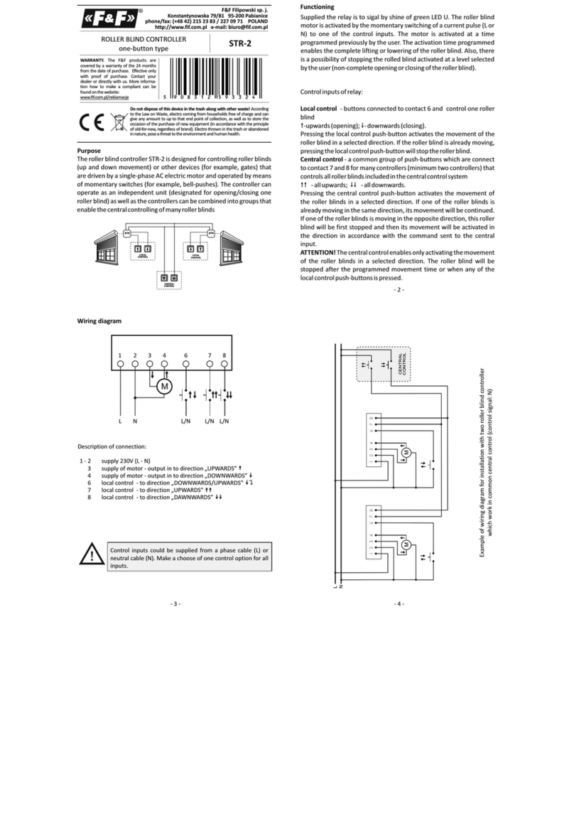
Controller of the roller-blinds with AC motors;
Cooperation with remote control transmitters of the F&Wave system;
The ability to control from up to 8 transmitters;
2 inputs for local control - the ability to directly control the relay using any mono-
stable button (for example: bell button);
2 output contacts for both directions of the roller-blind movement with a load
capacity of 0.6 A (AC-3);
Small enclosure size;
Screw terminals for easy installation in a ø60 flush-mounted box;
Retransmission of commands from the transmitter - the ability to increase the
range of the remote control;
Low power consumption - low operating cost;
Built-in electronic thermal protection to prevent damage in case of excessive load
of the controller;
Electric lock to prevent power supply switching on on both windings of the motor.
Description of the device

- 3 -
Wiring diagram
L - L power supply
N - N power supply
S1 - control input triggered with level L
or N - direction DOWN
S2 - control input triggered with level L
or N - direction UP
DÓŁ - output - direction DOWN
GÓRA - output - direction UP
Control inputs do not cooperate
with backlighted buttons.
Load capacity
0.6 A/250 V (AC-3)
The actual maximum load depends on the natu-
re and design of the receiver.
For more information visit: www.fif.com.pl.

- 4 -
Pairing
①After the device is properly connected, press and
hold the PROG button until the relay will switch on
and the communication LED will go off.
②Press the selected button on a remote control or in
a flush-mounted transmitter.
③Correct pairing will be confirmed by temporary switching off of the output
circuit and the LED will turn on again.
④
The remote control is programmed with the roller blind controller on the ba-
sis of pairs of buttons. For FW-RC5 and FW-RC10 transmitters the subsequ-
ent buttons are paired. For example, if the button "1" on the remote control
is paired with the receiver, then for the opposite direction of movement the
subsequent button "2" will be automatically paired.
For FW-RC4 transmitter are paired buttons that are vertically adjacent. For
example, if the button "1" on the remote control is paired with the receiver,
then for the opposite direction of movement button "3" will be automati-
cally paired.
The receiver can be paired with eight different transmitters (remote buttons).
Pairing with more buttons will remove the first entries made.
Unpairing
To clear the list of transmitters cooperating with the receiver, press the PROG button and hold it
down for at least 10 seconds. Fast flashing of communication LED will indicate that the memory
of the controller has been cleared.

- 5 -
Local buttons
Short press of a button activates the roller-blind in the selected direction of movement.
Subsequent press during the roller-blind movement causes it to stop.
Long press of a button (for longer than 5 seconds) activates the programming mode of the
passage time of the roller-blind.
Passage time programming
The default time of roller-blind passage is 30 seconds.
To change this time you need to:
unroll the roller blind to the maximum by pressing the down direction button;
when the roller-blind stops, release the down direction button and then press and hold the
up direction button of the roller-blind;
after 5 seconds the roller-blind will start to roll up, and when it stops in the utmost upper
position immediately release the up direction button;
time of the roller-blind passage can be adjusted in the range of 5÷120 seconds.
Remote buttons
The FW-RC4, FW-RC10 transmitter operate on the principle of a bistable switch:
one press of a button activates the roller-blind in a selected direction of movement,
the second press of a button during the movement of the roller-blind causes it to stop.
The FW-RC5 transmitter also has separate inputs ON (always raise the roller-blind)
and OFF (always lower the roller-blind).
Due to the nature of transmission and retransmission do not use the same button in
transmitter more often than every 2 seconds. Switching of the receiver may be carried
out with a short delay.
We do not recommend the use of remote bistable transmitters to control
a group of receivers due to the possibility of desynchronization of the activation state
(especially when operating on larger distances and/or simultaneous use of local but-
tons on the receivers).
Activation of the thermal protection is indicated by a steady pulsing of communication
LED, switching off of the output circuit and the lack of its reactivation possibility. After
lowering the temperature to a safe value the output circuit will remain switched off
until restarted.

- 6 -
.
Devices of the F&Wave system
Battery transmitters
Type Product
Flood sensor FW-FS1
Remote control FW-KEY, FW-RC4, FW-RC10
Wall button
FW-WS1, FW-WS2, FW-WS3
FW-WSO1, FW-WSO2, FW-WSO4
Flush-mounted box ø60 FW-RC5
AC transmitters
Type Product
Flush-mounted box ø60
FW-GS1, FW-GS2, FW-GS4
FW-RC4-AC
Receivers
Function Flush-mounted box ø60 DIN rail
Correct operation of LED light bulbs
with devices of the FW-...-NN series FW-BYPASS-NN ---
Universal dimmer FW-D1P FW-D1D
2-channel LED controller FW-LED2P FW-LED2D
Single relay FW-R1P FW-R1D
Single multifunction relay FW-R1P-P,
FW-R1-P-NN FW-R1D-P
Double relay FW-R2P FW-R2D
Double multifunction relay FW-R2P-P,
FW-R2P-NN FW-R2D-P
Roller blind controller FW-STR1P FW-STR1D
Roller blind multifunction controller FW-STR1P-P FW-STR1D-P

- 7 -
Technical data
power supply 85÷265 V AC/DC
control input 85÷265 V AC; <1 mA
power consumption
operating mode 1.00 W
standby 0.25 W
output load capacity (AC-1/AC-3) 3 A/0.6 A
radio frequency 868 MHz
maximum emitted frequency power 10 mW
working temperature -25÷65°C
terminal 2.5 mm² screw terminals
tightening torque (max) 0.4 Nm
mounting ø60 flush-mounted box
dimensions 48×48×25 mm
ingress protection IP20
Warranty
F&F products are covered by a 24 month warranty from the date of purchase.
The warranty is effective only with a proof of purchase.
Contact your dealer or directly with us.
CE declaration
F&F Filipowski L.P. declares that the device is in conformity with the essential require-
ments of Directive 2014/53/EU of the European Parliament and of the Council of 16
April 2014 on the harmonisation of the laws of the Member States relating to the ma-
king available on the market of radio equipment and repealing Directive 1999/5/EC.
The CE Declaration of Conformity, along with the references to the standards in rela-
tion to which conformity is declared, can be found at www.fif.com.pl on the product
page.
Compliance with the standards
PN-EN 55024:2011; PN-EN 60669-1:2006
PN-EN 60669-2-2:2008; PN-EN 62368-1:2015-03
PN-ETSI EN 300 220-1 V3.1.1:2017-08
PN-ETSI EN 300 220-2 V3.1.1:2017-08
PN-ETSI EN 301 489-1 V2.1.1:2017-08
PN-ETSI EN 301 489-3 V1.6.1:2014-03
E231103
Table of contents
Other F&F Controllers manuals