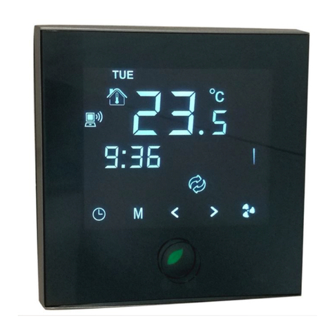
MAXA HI-T Use and care manual

Hi-T LCD touch-screen centralized controller for hydronic
terminal coupled with N-i-HWAK/WP V2/V2+ minichillers and
i-HP/i-HP LT chillers
AIR CONDITIONING
A86
USER’S AND INSTALLER’S MANUAL
Serie/Series/Serie/Série Emissione/Edition/Au-
sgabeIssue
Hi-T LCD Touch-Screen
Centralized Controller 04 – 2014
Catalogo/Catalogue/Katalog/Brochure Sostituisce/Superseedes
Ersetzt/Remplace
MUI01137E0120-00
–

Hi‐TCentralizedcontroller
1
0003‐2014A.M.G.M./
RevDateIssuedApprovedUpdatesdescription
Catalogo/Catalogue/Katalog/Catalogue
MUI01137E0120‐00
Serie/Series/Serie/Serie/Série
CONTROLLOREMOTOPERCHILLERETERMINALIIDRONICI
Theelectricalandelectronicproductsandanywasteshouldnotbedisposedofwithnormalhouseholdwaste,butdisposedofaccordingtolawinaccordance
withtheWEEEEUdirectives2002/96/ECand2003/108/ECasamended,andinquireattheplaceofresidenceorattheretailerinthecasewheretheproduct
isreplacedwithasimilarone.
NOTE:Thestatementsanddescribedinthismanualmaynotcoincidefullywiththedeviceinquestion(“Hi‐T:CentralizedControlLCDtouchscreenfor
hydronicterminalcoupledtoN‐i‐HWAK/WPV2/V2+minichillersandi‐HP/i‐HP‐LTchillers”).TheCompanyreservestherighttomakechangesandupldates
thanindicatedinnthismanual.

Hi‐TCentralizedcontroller
2
INDEX
1HI‐T:GENERALNOTES............................................................................................................................................. 4
1.1PERMITTEDUSE............................................................................................................................................................................4
1.2USENOTPERMITTED....................................................................................................................................................................4
1.3TECHNICALDATA..........................................................................................................................................................................4
1.4ELECTROMECHANICSCHARACTERISTICS .....................................................................................................................................4
2I/ORESOURCES ...................................................................................................................................................... 5
2.1TOUCHSCREENPCB .....................................................................................................................................................................5
2.1.1LAYOUT ....................................................................................................................................................................................5
2.1.2TOUCH‐SCREENUSE .................................................................................................................................................................5
2.1.3DISPLAY ....................................................................................................................................................................................5
2.1.4POWERSUPPLY ........................................................................................................................................................................5
2.1.5ANALOGUEINPUT ....................................................................................................................................................................5
2.1.6SERIALANDCONNECTIVITY......................................................................................................................................................5
2.2CLOCK...........................................................................................................................................................................................6
2.3CONNECTIONS..............................................................................................................................................................................6
2.1INSTALLING ..................................................................................................................................................................................6
3USERINTERFACE..................................................................................................................................................... 7
3.1ICONSDISPLAY .............................................................................................................................................................................7
3.2SCREENSANDICONS ....................................................................................................................................................................7
3.3STARTPAGE..................................................................................................................................................................................8
3.4HOMEPAGE .................................................................................................................................................................................8
3.4.1CHILLERSCREEN/HEATPUMP ..................................................................................................................................................10
3.4.2FANCOILPAGE..........................................................................................................................................................................13
3.4.3Hi‐TAREA .................................................................................................................................................................................15
3.4.4ETHERNETCONNECTIONCONFIGURATION .............................................................................................................................15
3.5SECONDMAINPAGE ....................................................................................................................................................................16
3.6HOMESYSTEM .............................................................................................................................................................................17
3.6.1STATUSSETUPPAGE ................................................................................................................................................................17
3.6.2SET‐POINTSETUPPAGE............................................................................................................................................................18
3.6.3PROGRAMSPAGE(CHRONOTHERMOSTAT).............................................................................................................................18
3.6.4SPECIALFUNCTIONSPAGE .......................................................................................................................................................19
3.6.5CONFIGURATIONPAGE ............................................................................................................................................................19
3.6.6HELPPAGE................................................................................................................................................................................22
4STATUSMACHINESANDFUNCTIONS...................................................................................................................... 23
4.1NEWTORKMANAGEMENT ...........................................................................................................................................................23
4.2REMOTECONTROLCONNECTEDWITHMORECHILLERINTHENETWORK ...................................................................................23
4.3CHILLER/HEATPUMPSMANAGMENT ..........................................................................................................................................24
4.3.1ENABLINGTHEINDIVIDUALCHILLERFORTHEPRODUCTIONOFSANITARYWATER ...............................................................24
4.4FANCOILMANAGE........................................................................................................................................................................24
4.5PROCEDUREBEFORESETTINGTHEHI‐TREMOTECONTROL ........................................................................................................24
4.5.1ADRESSING...............................................................................................................................................................................24
4.5.2SCANNETWORK .......................................................................................................................................................................25
4.5.3AREASFANCOILASSIGNMENTANDCUSTOMIZINGTHEAREA’SNAME .................................................................................25
4.6ASSOCIATESUNITOPERATION .....................................................................................................................................................25
4.6.1ON/OFF ....................................................................................................................................................................................25
4.6.2ON/OFFSANITARYMODE ........................................................................................................................................................26
4.6.3SET‐POINTSETUP .....................................................................................................................................................................28
4.6.4FANSETUP................................................................................................................................................................................29
4.6.5PROGRAMSSETUP(CHRONOTHERMOSTAT) ...........................................................................................................................29
4.7KEYBOARDSETTINGSPROCEDURE...............................................................................................................................................32
4.7.1SETTINGOFTHELANGUAGEANDOFTHEDATE/TIME ............................................................................................................32
4.8FAULTDIAGNOSTIC ......................................................................................................................................................................33
4.8.1ACTIVEALARMS .......................................................................................................................................................................33
4.8.2ALARMHISTORY.......................................................................................................................................................................33
4.9DOUBLESET‐POINTANDDEHUMIDIFICATIONFUNCTIONS .........................................................................................................33

Hi‐TCentralizedcontroller
3
4.9.1MEASUREMENTOFTEMPERATUREANDHUMIDITY ...............................................................................................................34
4.9.2DEWPOINTANDDEHUMIDUFUCATIONCONTROL .................................................................................................................34
4.10CLIMATICCOMPENSATION ..........................................................................................................................................................35
4.11OTHERFUNCTIONS.......................................................................................................................................................................35
4.12SPECIALFUNCTIONS.....................................................................................................................................................................35
4.12.1SCREEDFUNCTION ...............................................................................................................................................................36
4.13PASSWORDANDPROTECTIONS ...................................................................................................................................................36
5REMOTEACCESS..................................................................................................................................................... 37
5.1SECURITY......................................................................................................................................................................................37
5.2LOCALWEBSERVER......................................................................................................................................................................37
6FIRMWAREUPDATE ............................................................................................................................................... 41
7HNSSYSTEMDESCRIPTION ..................................................................................................................................... 42
8THEHNSBOX .......................................................................................................................................................... 44
8.1FUNCTIONS ..................................................................................................................................................................................44
8.2HNSBOXDESCRITPION...................................................................................................................................................................44
8.3CONNECTINGTHEHI‐TKEYBOARD,THECHILLERANDTHEHYDRONICUNITS .............................................................................45
DIPSWITCHESSETTING ............................................................................................................................................................................46
8.4WATERPROBE..............................................................................................................................................................................46
8.5AIRSENSOR ..................................................................................................................................................................................47
8.6WIRINGS.......................................................................................................................................................................................48

Hi‐TCentralizedcontroller
4
1Hi‐T:GENERALNOTES
1.1 PERMITTEDUSE
TheHi‐Tisatouchscreenremotecontrolforcentralizedmanagementofanetworkofchiller/heatpumpsystemandoftheHNS
system.Itcanalsobeusedforpartialfunctions(i.e.asaremotecontrolpanelforasinglechiller/heatpumporthermostatforsome
fancoilsmanagement).
Itintegrateshumidityandtemperaturesensorsforthethermohygrometricanalysisoftheenvironmentandforthemanagementof
thedoublesetpointforradiantfloorheatingsystemsthatuseadehumidificationsystem.
Theintuitiveinterfacesimplifierstheuseofthecontrol;allthefunctionsareeasilysetthroughtheuseofimmediateunderstanding
synoptic.
1.2 USENOTPERMITTED
AnyuseotherthanthatpermittedisPROHIBITED.
1.3 TECHNICALDATA
NominalMin.Max.
Powersupplyvoltage12Vac10Vac14Vac
Powersupplyfrequency50‐60HzTip‐5%Tip+5%
Operatingambienttemperature25°C0°C50°C
Operatinghumidity(non‐condensing)30%10%90%
Ambientstoragetemperature25°C‐20°C70°C
Ambientstoragehumidity(non‐condensing)30%10%90%
1.4 ELECTROMECHANICSCHARACTERISTICS
TerminalsandconnectorsScrewterminals
Analogueinputs1NTCprobeonboard
1humiditysensoronboard
Serial1USBHost(formassstorageplug)
1isolatedRS485networkforchiller/heatpumpandfan
coil
1TTLserialportforfutureuse(optionalplug‐ins)
1Ethernetport
TransformerDevicenotincluded
WatchRTCwatchwithbackupcondenser
DisplayLCDTFT4.3”480x272pixels
KeysResistivetouchscreenmountedontheLCD
Dimensions128x81.2mmdepth35mm(box)
CaseWhiteplastic

Hi‐TCentralizedcontroller
5
2I/ORESOURCES
2.1 TOUCHSCREENPCB
2.1.1 LAYOUT
Figure1.Layout.
2.1.2 TOUCH‐SCREENUSE
Theinterfacehasaresistivetouch‐screenLCDwithsensitiveareasappliedtothecontextualcontentoftheactivescreen.
Itallowsyoutoselectitemsorperformfunctionswithease.
Donotexerttoomuchpressureonthetouchscreenwithyourfingersanddonotuseasharpobjectonthetouchscreen.Doingso
maydamagethetouchscreenorcauseittomalfunction.
Itisadvisabletoexertweakerpressureandnottoofastonthescreenandtobecomefamiliarwiththeuseofthetouch‐screen
itself,wellcalibratingthetouchofyourfingertiponthesensitiveareasofthescreens.
Donotputthetouch‐screenincontactwithotherelectricaldevices.Electrostaticdischargemaycauseamalfunction.
2.1.3 DISPLAY
ThedisplayisaTFTLCD16/9formatwithadiagonal4.3".Theresolutionis480x272pixels.TheLCDishandledwith16bitcolour
depth(65535colours).
2.1.4 POWERSUPPLY
DescriptionCharacteristicsID
POWERSUPPLY12VAC12Vac(min.10Vac–max.14Vac)
2.1.5 ANALOGUEINPUT
DescriptionCharacteristicsID
RoomtemperatureNTCprobe,conversionrange‐20°C÷+100°C
Relativehumidity0%‐90%attemperaturebetween‐20°Cand60°C
2.1.6 SERIALANDCONNECTIVITY
DescriptionCharacteristicsID
USBUSBHost(formassstorageplug)/connectortypeAUSB
RS485isolateIsolatedRS485toModbusSerialchiller/heatpumpandfancoil
TTLModbusserialTTLforfutureuse
ETHEthernetport10/100BASETforminimalweb‐server

Hi‐TCentralizedcontroller
6
2.2 CLOCK
It’spresentaclockwithbackupbattery.
2.3 CONNECTIONS
Openthecontrolapplyingaslightpressureinthelowerandupperpartsofthecontrol,inordertoseparatetherearcoverfromthe
frontone.Passthecablesthroughtheholeintherearpanelandmakeconnectionsaccordingtothefollowingguidelines.
Terminals1and2:12Vacpowerconnectsupply(terminalonchiller12V‐e12V+).
Terminals3‐4‐5:connecttheRS‐485bus:terminal3toterminalGNDR,terminal4toR‐andterminal5toR+.
R+
R-
12V+
12V-
GND
12345678
12 11 10 9
Figure2.Connections.
2.1 INSTALLING
TheHi‐Tcontrolisusedforfixingtothewallaccordingtothestandard503.
Intherearpartofthecontrolsomepre‐drilledholesarepresenttobedetachedpursuingapressurewithascrewdriver,insucha
wayastoobtaintheholesusefultothefixing.Ofthe6holes,useonlytheouter2holesofthehorizontalseries(seeFigure3).
Beforeyoudothis,openthecontrolitself,applyingaslightpressureinthelowerandupperpartsofthecontrol,inorderto
separatetherearcoverfromthefrontone.
Usetherearpanelandapplytheholesinthetwoslotsshowninthefigurebelow.
Donotdirectlyusethepanelasatemplatetodrilltheholesonthewall,theelectronicsmaybedamagedduringthisoperation.
Figure3.Holesforwallmounting.

Hi‐TCentralizedcontroller
7
3USERINTERFACE
Thetouch‐screencanbeusedinthefollowingways:
•Interfacepanel(unitinterface)forasingleheatpump
•Networkcontrollerformultiheatpumpinstallation
•Networkcontrollerformultiheatpumpandfancoilinstallation
•Networkcontrollerformultifancoilinstallation
Tomanagethesystemmodularity,theinterfaceforeseesahomepagewhichsummarizesthewholeplant,showingdynamicallythe
enabledresourcesandhidingtheonesnotavailableinthecurrentconfiguration.Theinterfacealsoprovidesasecondsummary
pageincludingallthevaluesoftemperatureandhumiditydetectedinthesystem.
Throughthemenuitispossibletoaccessto:
•Plantconfiguration
•Singleunitsstatuses
•Zones,machinesandplantsettings
Asalternativeitispossibletodirectlyaccessfromthehomepagetodetailedinformation,pressingonthedisplaywherearelocated
thesummarizedinformation.E.g.,pressingwherearelocatedthemaininformationoftheheatpump,youcanenterinthemenuof
theheatpumpstatus.
3.1 ICONSDISPLAY
Alliconsonthedifferentscreenscanbeshowninfullcoloursorde‐saturatedasinthefollowingexample:
Thecoloursaturationindicatesthaticonisusable;whenpressedtherelatedfunctionisperformed.
Thetransparency(de‐saturated)indicatesthaticonisnotusableandanytouchonithasnoresultingaction.
Forwhatconcernsthesideslidingbarwhichappearsontheleftsideofthescreenrelatedtothesingleunitsconnectedintoa
network(seeParagraphs3.4.1.3e3.4.2.1),ifaniconappearsfullycolouredtherelatedfunctionisenabledand,inthatspecific
momentisalsoactive(i.e.ifthe“wateranti‐freeze”iconoftheheatpumpispresentandcoloured,asshownbelow,theplate
exchangerelectricalheatingelementsareswitchedon).
Instead,iftheiconappearsbutistransparent(de‐saturated),therelatedfunctionisenabledbutnotthatmomentactivated(i.e.if
the“wateranti‐freeze”iconoftheheatpumpappearstransparent,asshownbelow,theplateexchangerelectricalheating
elementsarereadytoworkbutcurrentlyswitchedoff).
3.2 SCREENSANDICONS
Theremightbesomedifferencesbetweenscreensandiconsastheyarecurrentlyshown.TheCompanyreservesitselftomodify
andupdatethemwithoutpriornoticeandinrelationtowhatshowninthepresentmanual.

Hi‐TCentralizedcontroller
8
3.3 STARTPAGE
Figure4.Startpage.
OnHi‐Tstart,whilesystemloading,asplashscreenappearswithalogo.
3.4 HOMEPAGE
Thehomepagehasthefollowingappearance:
Figure5.Homepage–indicationmeanings.
Fromthehomepageitispossibletoaccesstothedifferentdevice’sscreens,simplytouchingthedisplayedresource.
Thesensibleareas(indicatedintheimagebyredboxes)insidethispageare:
1. Heatpump/chiller(showingtheworkingmode)
2. Statussystemandmodesystemdisplay
3. Fancoil(withastatusmessageofdehumidificationactivemode)
4. Displayofanyactivealarmsinthesystem
5. Informationandlocationofthecompany
6. Nameofthekeyboard(accesstoinformationonthefirmwareversion)
7. ConfiguringtheEthernetnetwork
8. Log‐out(intermittentsymbolifit’sactive)
9. Arrownavigation,nextpage.
2
3
1
11
12
13
5 6
4
7
8
9
10

Hi‐TCentralizedcontroller
9
Graphically,italsocontainsinformationonthepresenceorabsenceonthefollowingutilities:
10. Tank
11. Radiantpanels
12. Sanitary
13. Solar.
Onthemainscreen,infact,itappearsonlyutilitiespresentandproperlyinstalledinthenetworkortheactivewarningsatthetime
ofviewing.
If,forexample,thenetworkconsistsonlyofoneormorechiller/heatpumps,withoutproductionofsanitarywaterandwithout
storage,thescreenshowsgraphicallythepresenceofthechiller,butinsidethehousedonotappearotherobject;inthiscasethe
appearanceisthefollowing:
Figure6.Homescreen–onlychillerisnetworked.
Figure7.Chiller/HeatPump.
Referringtotheabovefigureisitpossibletoobtainthefollowinginformation:
•presenceofchillersconnectedinthenetwork(thechilleriscorrectlyacceptedwhentouchingitsfigureyoucanaccessto
thepagesdedicatedtoitself);
•operatingmodeofthechiller(winter,summer,sanitary,OFFifdoesnotappeartheprevious
threesymbols);
•operatingstatusofthechiller(compressorrunning):theoperationofthechillershowsgraphicallybytherotationofthe
fans).

Hi‐TCentralizedcontroller
10
Inaddition,directlyonthehomepage,youcangetthefollowinginformationaboutthefancoils:
•Presenceoffancoilsconnectedinanetwork,ifthesymbolappears(Figure8.Fancoilnetwork.);
•Dehumidificationfancoiloperation,ifthesymbolofthedropsappears(Figure9.Fancoildehumidification.).
Figure8.Fancoilnetwork.
Figure9.Fancoildehumidification.
3.4.1 CHILLERSCREEN/HEATPUMP
Fromthemainpage,bytouchingthesymbolofthechiller(sensitiveareanumber1,Figure5.Homepage–indicationmeanings.),
youcanaccesstothechilleronnetworkscreen.
Fromhereyoucanaccesstotheinformationrelatedtotheoperationsofthechiller;thenyoucanuniquelyidentifyeachchiller
present,assigningeachaname.
Figure10.Chillerpage–informationandsensitiveareas.
Theinformationinthechiller’spageare:
1. Temperaturereadinthechiller(abouttoaspecificchiller):
a. Airtemperature(°C)
b. Inletwatertemperature(°C)
c. Outletwatertemperature(°C)
2. Statusandoperationmodeaboutaspecificchiller
3. Active/activablefunctions(inthescrollbarontheleft)
Sensitiveareas(indicatedbyredboxesinthefigure)inthispageare:
1. Chillername(eachtimeyoupressonit,yougotothenextchillerunitinthenetwork;otherwise,withprolongedpressure,
youcanrenamethechiller)
2. Chiller/heatpump(withworkingsignallingfunctiongivenbytherotationofthefans);fromhereyouaccesstoanadditional
pageofinformationaboutthatspecificchiller.
3. Activealarmsintheunitdisplayed
7. Iconsofthenavigationsidebar
8. Iconsofthenavigationsidebar
5
3
7
4
1
2
6
8
9

Hi‐TCentralizedcontroller
11
9.Iconsofthenavigationsidebar
3.4.1.1 ASSIGNMENTOFNAMESTOTHECHILLERS
Fortheassignmentofthenametoachiller,youmustnavigatebetweenthepagesofthechillerconnectedtothenetworkuntilyou
gettothepageofthechillerwhichyouwanttochangethename:forapplythis,youhavetomakesinglepressintothepressure
sensitivearea4.Onceyoufindthechiller,pressandholdforafewsecondsinthesamearea4.Thencomposewiththekeyboard
thatappearsthedesiredname.
Figure11.Insertchillername.
Thenameofthechillercanhaveamaximumof13characters.
3.4.1.2 CHILLERAREA
Thearea5showninFigure10givesindicationsabouttheoperation(compressorrunning)ofthechiller,graphicallydisplayingthe
fanrotation.
Pushingdownonthearea5youaccesstoafurtherscreenthatshowsalistofreaddatainrealtimerelatedtotheinvolvedchiller:
•Inletwatertemperature(°C)
•Outletwatertemperature(°C)
•Sanitaryprobetemperature(ifit’spresentandconfigured,°C).
Accessingthesamepagewithserviceormanufactureraccessright(toenabletheaccessright,pressonthe“configurations”icon
presentinthesensitivearea8ofFigure10andsettheservice/manufacturerpassword),thedatadisplayedinreal‐timeare:
•Inletwatertemperature(°C)
•Outletwatertemperature(°C)
•Sanitaryprobetemperature(ifit’spresentandconfigured)
•Highpressure(bar)
•Lowpressure(bar)
•Compressorspeed(Hz)
•Openingexpansionvalve(step)
•Fanspeed(%)
•Pumpspeed(%)
•Overheating(°C)
•Compressoroperatinghours(Hr.)
•Pumpoperatinghours(Hr.)

Hi‐TCentralizedcontroller
12
3.4.1.3 TOOLBARCHILLERAREA
Ontheleftscrollsidebarthereareiconsthatsymbolizetheactive/activablefunctionsinthechillertakenintoaccount.Inparticular:
Colourfulicon=functionenabled,
Fadedicon=functionconfiguredonthemachinebutnotcurrentlyactive.
Belowthereisatablewithiconsthatmayappearinthescrollsidebar.
Thepresenceorabsenceoftheiconinthesidebarwillbedeterminedbytheenableordisableofthefunctiononthechiller.
ORDEROFAPPARANCEICONFUNCTION
1
SANITARYHOTWATER
2
SANITARYINTEGRATIONRESISTANCE
3
PLANTINTEGRATIONRESISTANCE
4
BOILERENABLING
5
DOUBLESET‐POINT
6
DEHUMIDIFYING
7
SLABFEATURE
8
DEFROST
9
ANTIFREEZEWATER
10
ANTIFREEZETRAYRESISTANCE
Table1.Orderofappearanceoftheiconsinthetoolbaronthechiller.

Hi‐TCentralizedcontroller
13
3.4.1.4 NAVIGATIONAREA
Inthetoolbarthatappearsattherightsideofthechillers’page,threeiconsareshownforthenavigationbetweenthepages:
Thefirsticononthetopallowsyoutoreturntothepreviousscreen,thesecondallowsyoutoenablemaintainer/manufacturer
accessrightsthroughapasswordtofurtherinformationinreal‐time,thelastreturnstotheHomescreen.
Thelowerpartshowsdateandtime.
Ifaniconappearstransparent,itisnotaccessible.
3.4.2 FANCOILPAGE
Fromthemainpage,bytouchingthesymbolofthefancoil(hotspotnumber3,Figure5),youenterthescreenofthefancoilson
thenetwork.
Fromhereyoucanaccesstheinformationrelatedtotheoperationoftheindividualfancoil,identifiedbyareaofbelongingand
identificationnumberoftheindividualfancoil.
Figure12.Informationfancoilspageandsensitiveareas.
Thesensitiveareas(indicatedbyredboxesinthefigure)inthisscreenare:
1. Activealarmsofthedisplayedunit
2. Nameofthefancoils(itshowsthenameofthezonetowhichthefancoilbelongsandtheidentificationnumberofthefan
coilunit;foreachpressureontheareaname,youmovetonextthefancoilunitinthenetwork)
3.Iconsofthenavigationsidebar
4.Iconsofthenavigationsidebar
5.Iconsofthenavigationsidebar
Theinformationonthefancoilspageis:
6. Temperaturesreadinthefancoilzones(averagetemperatureofthefancoilsinthearea)
a. Airtemperature(°C)
b. Inletwatertemperature(°C)
6
8
7
1
2
3
4
5

Hi‐TCentralizedcontroller
14
7. Statusandmodeofoperationrelatedtoaspecificfancoil(withfanspeed)
8. Active/activablefunctions(inthescrollbarontheleft)
Pressingtheconfigurationsymbol(SensitiveArea4)leadstothesettingofventilation.Theventilationischangedforzones;hence
changingtheventilationofafancoilofagivenarea,thechangesareappliedtotheentirearea.Thepageforsettingtheventilation
lookslikethis:
Figure13.Ventilationspeedconfiguration.
Thespeedcanbesetare:
•Minimumspeed
•Averagespeed
•Maximumspeed
•Automaticregulation(auto‐mode)
Withtheupanddownarrowsyouchoosethespeed,withthegreenbuttonyouconfirmthevalueset.
3.4.2.1 TOOLBAROPERATIONFANCOILAREA
Intheleftscrollsidebarthereareiconsthatsymbolizetheactive/activablefunctionsinthefancoilzoneconsidered.Inparticular:
Colourfulicon=functionenabled,
Fadedicon=functionunitconfiguredbutnotcurrentlyactive.
Belowthereisatablewithiconsthatmayappearinthescrollsidebar.
Thepresenceorabsenceoftheiconinthesidebarwillbedeterminedbytheenableordisableofthefunctionwhichyoureferon
boardthefancoilunit.
ORDEROFAPPARANCEICONFUNCTION
1
WINDOWSWITCH
2
DOUBLESET‐POINT
3
HUMIDITYCONTROL
Table2.Orderofappearanceoftheiconsinthetoolbaronthefancoil.

Hi‐TCentralizedcontroller
15
3.4.3 Hi‐TAREA
Pressinginthesensitivearea6ofFigure5,youhaveaccesstoascreenshowingtheversionandthedateofreleaseofthefirmware
installed.
3.4.4 ETHERNETCONNECTIONCONFIGURATION
Pressinginthesensitivearea7ofFigure5,itappearsthepage:
Figure14.Ethernetnetworkconfigurationpage.
OnthispagetherearetheaddressesfortheconfigurationofanEthernetconnection.
Logginginwithmaintainer/manufacturerpermission,youcanchangethedefaultaddresses.
It’simplementedalocalwebservertoaccesstotheHi‐TfromlocalareanetworkwithaHTML4.01compatiblebrowser(see
Paragraph5.2).

Hi‐TCentralizedcontroller
16
3.5 SECONDMAINPAGE
Fromthehomepage,touchingthearrowicontonavigatetothenextscreen,yougotoasecondscreenshowingallofthe
detectionscarriedoutbythetemperaturesensorsandhumiditysensorsinthesystem.
Figure 15. Second Main page.
Referringtothefigureabove:
•Field1indicatesthezonetowhichyouarereferring;applyingpressureonit,youswitchtothenextzone.
•Field2indicatesthefancoilwhichisreferencedwithinthezoneselectedfromthefield1;pressingonittheindexofthe
selectedzoneprogressesinacyclicmanner,givingawayallthefancoilunitsinthearea.Foreachfancoilisshownthe
detectedairtemperature.Theseindicationsappearonlyiftherearefancoilsconfiguredinthesystem.
•Field3indicatesthechillerwhichitrefers;bypressingonit,youprogresstothenextchillerinthenetwork.Foreachchiller
shown,youseethereadingsonthetemperatureofthewaterinletandoutletofthechillerandontheairtemperature
measuredbytheprobesonboard.
•Field4showstheambienttemperatureandtherelativehumiditymeasuredbythesensorsintegratedintheHi‐Tpanel.
•Field5indicatesthepresenceofthesolarsystem;thentheindicationonthetemperatureofthesolarpanelsisshown.
Theseindicationsappearonlyifinthesystemisconfiguredasolarpanel.
•Field6showstheenablingoftheproductionofdomestichotwaterrelatedtothechillerselectedfromfield3.Italso
indicatesthetemperatureofthedomestichotwaterproduction.
•Field7indicatesthepresenceofastoragetankconnectedtothechillerselectedfromfield3.Italsoindicatesthe
temperatureofthedomestichotwaterproduction.
•Field8indicatesthepresenceofradiantfloor;thisfieldisconnectedtotheenablingofthefunctionofdoubleset‐point.
Inthecaseofprobesinerrorornotproperlyconfiguredandconnected,itappearstheindicationoferror.
NOTE:Thepresenceofaccumulationandthesanitarymodeareherereferredtothefactthatinthenetworkispresentaheatpump
inwhichthesanitarymodeisenabled.
5
3 7
4
1
2
68

Hi‐TCentralizedcontroller
17
3.6 HOMESYSTEM
Fromthesecondpage,touchingthearrowicontonavigatetothenextscreen,yougotoathirdscreenforgeneralsettings,the
"systemmainpage",showingthefollowingfunctionalicons:
Figure16.Systemmainpage.
Above,fromthelefttoright:
1) STATUSSETUP;
2) SET‐POINTSETUP;
3) PROGRAMSANDCHRONO‐THERMOSTAT.
Inthebottom,fromthelefttoright:
4) SPECIALFUNCTIONS;
5) CONFIGURATION;
6) HELPMENU.
3.6.1 STATUSSETUPPAGE
Pressingtheiconabove,youaccesstothepage:“Statussetup”.
Figure17.“Statussetup”page.
Pushingon“System”youcansetthestatusoftheentiresystem,otherwiseyoucanactonindividualunit.

Hi‐TCentralizedcontroller
18
3.6.2 SET‐POINTSETUPPAGE
Pushingontheiconabove,youaccesstothepage:“Set‐pointsetup”.
Figure18.“Set‐pointsetup”page.
Fromthisscreenyoucansetthechiller’setandfancoilzonesconfigured.Ifenabled,youcanalsosetthesanitaryhotwaterset(see
Paragraph4.6.2),thesecondset‐point(seeParagraph4.9)andtheoffsetfortheclimaticcompensation(seeParagraph4.10).
3.6.3 PROGRAMSPAGE(CHRONOTHERMOSTAT)
Pushingontheiconabovetoaccessthepage“Programs”.
Figure19.“Programs”page.
Fromthispageyoucansettheweeklyprogramofchillersandfancoilzonesseparately.Youcanalsoprogramthelegionella’scycle
andtheproductionofhotwater,ifenabled(seeParagraph4.6.5).

Hi‐TCentralizedcontroller
19
3.6.4 SPECIALFUNCTIONSPAGE
Pressingtheiconabovetoaccessthepage"SpecialFunctions"(seeParagraph4.12).
3.6.5 CONFIGURATIONPAGE
Pushingontheiconabove,youenterintothepage"Configuration".
Figure20.“Configuration”page.
Fromtheconfigurationscreen,youcanaccesstotheUser‐Setupmenu,totheservicemenuandtothemanufacturermenu.
Pushingoneachoftheseitems,itappearsanumerickeypadforenteringapassword.
Figure21.Passwordentry.
Theuserpasswordissetbydefaultto"0"(modifiable).
Table of contents
Other MAXA Controllers manuals
Popular Controllers manuals by other brands

Alicat Scientific
Alicat Scientific MC Series operating manual

LOVATO ELECTRIC
LOVATO ELECTRIC RGK600 installation manual

Avipas
Avipas AV-3104SE user manual

SMC Networks
SMC Networks CRB2BW40 Series Operation manual

Vetus
Vetus SENSORD Operation manual and installation instructions

Redarc
Redarc Tow-Pro Elite manual

Associated Equipment
Associated Equipment KwikStart Pro Series Operator's manual

Entity
Entity DomoVoice EN1650 user manual

Lovato
Lovato RGK700 instruction manual

Viqua
Viqua BA-ICE-S manual

Moore
Moore 500 Series Hardware Installation and Modification Manual

KMC Controls
KMC Controls CSC 3000 Series Application guide