BOHYUN BY- 6S User manual

Wheel Balancer
BY- 6S
User Manual

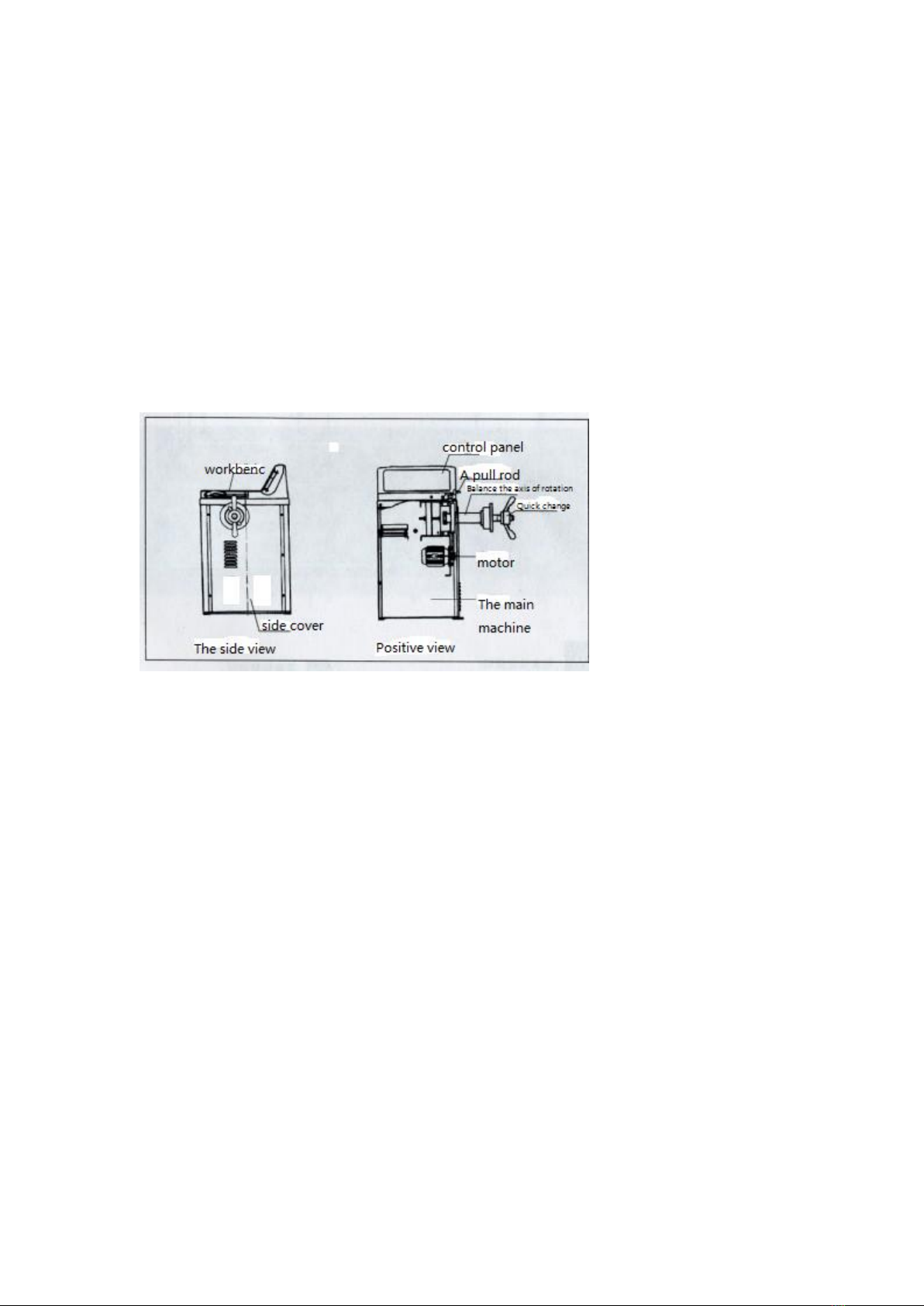
Technical performance of BY series tire balancer
-This machine adopts central computer system imported components, high
intelligence, high stability.
-The main shaft of the mechanism is driven by imported bearing, with high
wear-resisting precision and low noise.
-With the most advanced computer drive system, high stability.
-With automatic dynamic and static balance detection function.
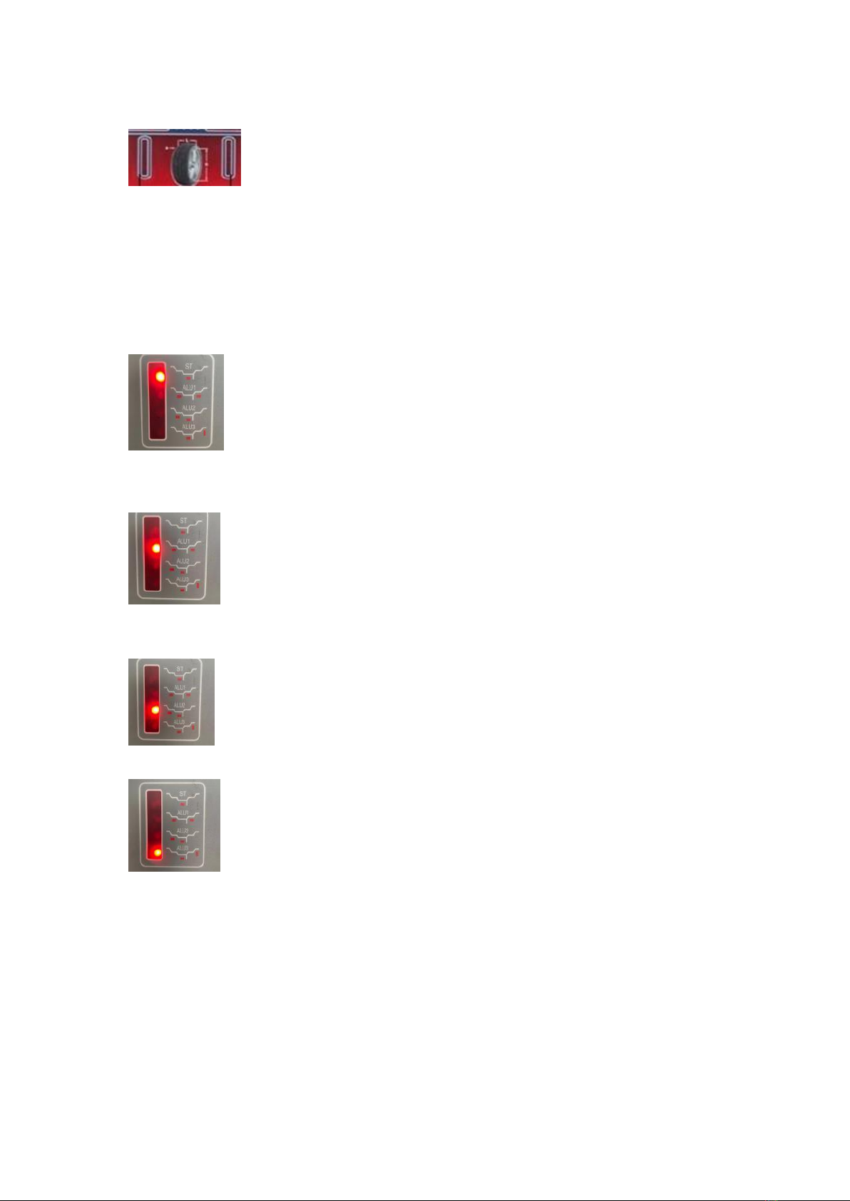
-With the function of balancing three kinds of aluminum alloy steel rings.
-It has self - correction and self - diagnosis function.
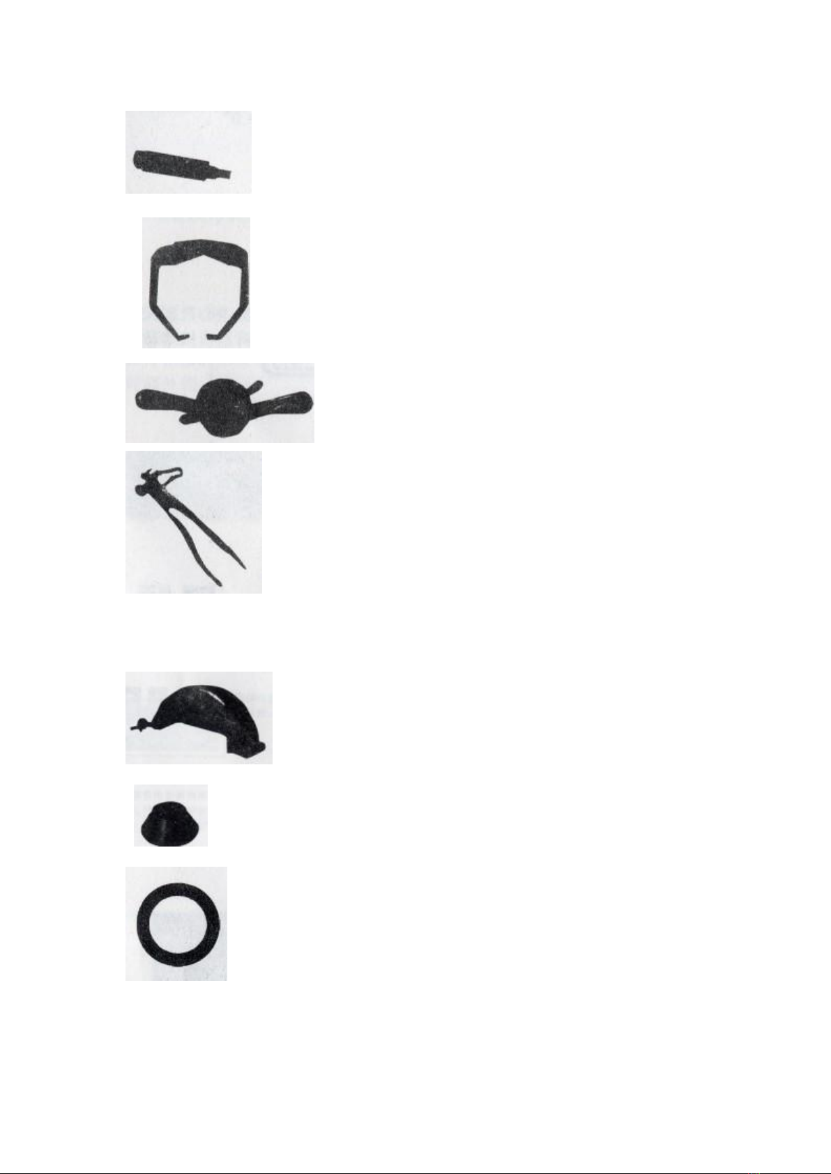
The machine can be used to balance the lead
1.Code Balancer
(Common steel and aluminium alloy steel rings)
2. Paste Balance Block
(aluminium alloy steel ring)
Note: the weight error of the balance block can directly affect the detection effect of
this machine.
Attention to the Use of Installation Box
1. Do not the tire balancer in extreme temperature and humidity. Avoid placing beside
heating equipment, faucets, air humidifiers or stoves.
2. Don't put the balance machine in front of the window where the sun can directly
enter. In unavoidable cases, curtains, baffles or shields should be used to shield the
balancer.
3. Avoid contact with large amounts of dust, ammonia, alcohol, diluents or spray
adhesives.
4. The balancer should be fixed on a smooth ground. Avoid placement next to air
compressors or objects that may vibrate.
5. Do not approach the machine when using.
6. The specification of the power outlet of the tire balancing machine is 110 v volts
( AC) with a rated output current of at least 10 A( amperes).
7. Tire balancing machine should use a separate power outlet, do not connect other
wires to the power outlet of the balancing machine, and note that the socket must be

reliably connected to the power cord of the balancing machine to avoid human
stampede.
8. Between the back and the wall of the balancer, there should be a distance of 50
CM to ensure good ventilation and heat dissipation.
9. Contact your maintenance service personnel before moving the balance machine.
BY main components of tire balancer

Installation debugging method
1. Switch on and display HLP
2. Press F+FINE key to display the window is lit up
3. Press ALU key to enter the setting program. The current spindle tooth position is
displayed, and the spindle can be rotated forward and backward to check the
phototelex Sensory work.
4. Go to the spindle to 114, press Start, enter the spindle distance setting (the default
value is 195, which can be skipped if it is consistent with the real boundary) and
measure to the outer edge of the spindle flange with a ruler.
Enter the measured value with B + or B -.
Press A + to exit.
5. Go to the spindle -0-, press Start key, enter the spindle zero clearance program,
(this program can clear the spindle since
Press Start key to START the spindle, automatically reset and store and exit.
6. Press C to exit.
7. Put on the tire, input the tire data and then press F+C key to calibrate.
8. Press Start to display Add 100 after starting. Rotate the tire until the outside spot
lights are all on, outside the tire
After hanging 100 grams of lead blocks above the spindle, press START to display
100 ADD. Remove the outside 100 grams of lead blocks, turn the tire to the inside
point lights are all on. After hanging 100 grams of lead blocks above the inside spindle
of the tire, press START to display END CAL.
Balancing machine debugging is over.

Aging of balancing machine
1. Press F+FINE key to display the window is lit up
2. Press ALU key to enter the setting program. The current spindle tooth position is
displayed, and the spindle can be rotated forward and backward to check the
phototelex Sensory work.
3. Turn to the spindle to 100 and press Start to enter the aging procedure for 100
times.
Press START
Key after startup and count to start 100 times after the end of the buzzer prompt.
Balancing machine self check
1. Press F+FINE key to display the window is lit up
2. Press ALU key to enter the setting program. The current spindle tooth position is
displayed, and the spindle can be rotated forward and backward to check the work of
the photoelectric sensor.
Forward loops are added from 0 to 127, and reverse loops are reduced from 127 to 0.
You can also check the red light on the photoelectric plate, slowly turn the spindle, and
the red light will flicker alternately.
3. Press ALU button again to enter the pressure sensor detection.
The values of about 60 to 70 are displayed on both sides respectively. When the
spindle is pressed by hand, the values on both sides will change, which proves that
the two sensors work normally.
BY series tire balancer standard accessories

screw
Width measuring calipe
Quick change of nuts
Balance block disassembly clamp
Optional accessories for BY series tire balancer
shield
Special - made large cone
Special - made fl ange
Standard Annex for Tire Balancer (List)
Balance block disassembly clamp 1

Width measuring caliper 1
Axial - positioning cone 4
Quick - change nut 1
Balancer Lead Screw 1
Basic operation of tire balancer
1. turn on the power switch on the left side of the machine to display 411, and then the
display 9,10 to A ","8.0".
2. installation of tyres
Select the axis cone matching the center hole of the rim, install it in the center of the
rotating shaft, and lock it with a quick change nut. (The maximum weight of the wheel
must not be greater than 70 Kg).
3. input A value data.
Pull the A ruler to the position of the rim mounting balance block and press
push-button,enter the data on the pull ruler into the display 10, where the display 9 is
A"

4. Enter the L value data
Measure the width of the cali per in the attachment , press the button to input
the data on the cali per into the display , when the display is " L"
5. input D value data
After confirming the rim diameter, press the button to enter the data into the
display 10, where the display 9 is D"
6. press the start button
Start operation, a few seconds later, the machine automatically stops.
(B type pull down shield, can run automatically. )
7. shows imbalance
At this point the number of display 9,10 is the tire imbalance, with the hand to turn the
wheel, positioning constantly flashing.
8. until (11),(12) one of the indicator lights are fully lit, indicating that the highest rim is
an unbalanced point at this time, where (11) represents the inner side point of the rim
and (12) represents the outer side point of the rim.
9. the corresponding balance block measured by the display at the rim imbalance
point, the display 9 represents the inner side of the rim and the display 10 represents
the outer side of the rim.

10. Repeat the operation steps 6 to 9 until 9,10 shows "00".
11 . Remove the wheel from the balance rotation shaft and end the operation
procedure .
Function Select
When this light is on, it is suitable for other tires on both sides of motorcycle tires or
rims which can not be balanced
When this light is on, it is suitable for the alloy ring tire with the balance block attached
to the shoulder of the rim.
When the light is on , the outside of the rim and the clip balance block on the inside .
When this light is on, it is suitable for the alloy ring tire which is pasted on the outer
side of the alloy rim.
When the four sets of indicators are out , the standard balance mode (the computer is
automatically set each time it is turned on) .

BY Series Balance Computer Self-Def code
1. no rotation signal, motor does not turn or position sensor position is wrong, sensor
bad and plug contact, computer board bad, etc.
2., the coil speed is less than 60 rpm, during the measurement of the computer phone.
Too loose and too tight tires and belts can cause errors.
3.the calculation error, the unbalanced amount exceeds the operation range.
4. motor reversal, position sensor wiring error.
5. press the start key, the protective cover is open.
6. self - calibration errors or self - calibration data loss requires re - calibration .
7. data memory content is lost or damaged.
8. a self-calibration error, it may be the second rotation without adding 100g of
balance or Pressure sensor cable broken, pressure sensor broken, plug contact poor.

Main Technical Specification
Motor
110 V, 60 Hz, 1 Ph, 1.5 HP ( 1.1 kW )
Working Temperature
32 ℉- 122 ℉( 0 ℃- 50 ℃), humidity ≤ 80 %
Cycle Time
6 to 9 seconds
Data Entry
Keypad
Balancing Modes
Dynamic / Static / Alloy
Rim Diameter Capacity
10 - 26 in ( 254 - 660 mm )
Rim Width Capacity
1.5 - 20 in ( 38 - 508 mm )
Max. Wheel Diameter
50 in ( 1270 mm )
Max. Wheel Weight
143 lbs ( 65 kg )
Shaft Size
36 mm
Max. Shaft Weight
176 lbs ( 80 kg )
Balancing Speed
180 RPM
Accuracy
0.035 ounces ( 1 gram )
Display
Standard Or Metric
Self Calibration
Yes
Power Cord Length
78 47/64 in ( 2000 mm )
Noise Level
< 75 dB
Product Dimensions
L 23.62 x W 37.40 x H 36.22 in ( 600 x 950 x 920 mm )
Product Weight
198.42 lbs ( 90 kg )
Daily use and precautions of balancer
1.balancer must remove the packaging bottom plate, fixed installation smooth.
2.The casing must be grounded protected .
3.It is forbidden to move the spindle of the balancing machine and not to cause any
collision of the spindle.
4.Dam - proof measures shall be taken to extend the service life of the peace
machine .
5.Attention to the use of power supply, voltage up to 110V, it is recommended to
configure voltage regulator.

General common faults and troubleshooting methods :
Failure performance
Fault cause
Remedy
Not on display
1.Check external circuit 220v
for normal .
2.power supply board failure.
3.power supply board to the
computer connection line is
loose .
4.computer board has failed .
1.Check the external power
supply.
2.Replace the power board.
3.Check the plug connection.
4. Replace the computer.
Display is normal , but start
switch and A, The L, C input
button fails .
1.The touch switch is in poor
contact.
2. Dead.
1.Open the cover and plug in
the touch switch plug.
2.Reboot.
Normal but no brakes after
starting
1. computer board and power
board connection loose.
2.Power board malfunction
3.Computer board
malfunction
1.Plug the computer board to
the power board .
2.Re place the power supply
board .
3.Re the computer board .
Slow slow brake not
working, flat value not
allowed
The belt is too loose.
Adjust motor position or
replace belt.
Use is normal, but the flat
value is not correct.
1. instrument is unstable.
2. Effect of cone or quick nut.
3. Abnormal or not on wheels
Tight.
The power supply in the
machine is unstable.
The external circuit voltage
fluctuates too much.
6. Change of calibration
value.
7. Memory change.
The 1. is excluded according
to the inspection results .
The 2.resets the fast nut .
3. Check for normal power
plug
4. users resolve grid
instability
Fixed the same time .
5. if the fault is
troubleshooting ,
Re place the computer
board .
6. is adjusted according to
the method .
7. is adjusted according to
the method .
8. will re - enter the three
dis\In-1\SFA parameters by
the parameter value
calibrated in the chassis ,
then adjust and check if the
machine is normal .

Method of adjusting three parameter values:
In normal use, if there is too much or uneven lead block phenomenon, first of all, if the
above phenomenon occurs under self-calibration, then adjust the parameters of the
triplet.
1. adjustment angle SFA value: after self-calibration, it is found that the position of
100g lead block is not directly below the spindle or the value is not correct, Can use
this function to see 100 grams of lead block imitation off the spindle about how many
degrees. Remove this lead and hold down the R and START start keys, About nine
seconds later, The monitor stops flashing, Press the A value corresponding to the (-)
key after pressing the corresponding (+) key display when all the (F) key at this time
the left display window appears dis symbol, On the right, Without thinking about it,
Press the (+) key corresponding to the A value again (where the key represents the
entry) to display the value on In—1 right, Press the A (+) to get into the SFA window,
The right window shows the value of the position of the 100 g lead block. When it is
necessary to change its value. You can press the (+) of the L key or (-) to adjust the
deviation of 100 grams from the spindle at self-calibration, Keep pressing A
corresponding (+) key to exit, Back to school, Sometimes it is necessary to adjust the
SFA value to 100 g lead block directly below the spindle.
2.adjust the dis value: this is used to solve the problem of inner inaccuracy, flatten the
rim, put 100g lead block on the outside, see the value on the display window should
be in the range of 104-96, take 100g lead block on the inside, if the display value is
normal in the range 104-96, If the search method is the same as the SFA value, adjust
the (+)(-) key to the L key.
3. adjust In-1 value: this can solve the problem of internal and external score, If you
put 100 grams of lead on the inside, If the inside shows 990, If the number is 10, you
need to adjust this, After self-calibration, enter I n-1, state to adjust memory value In-1
value (the (+)(-) key corresponds to the L key) if the display value exceeds 110 g,
Need to reduce this, After the completion of the retreat to the initial state of
self-calibration.
(1).CB series balancer operation panel to UP represent (+) key, DOWN represent (-)
key.
(2).CB series balancer operation panel represents (R) key SEL (F) key.
3.adjusting the values of the three parameters, be sure to unload 100 grams of lead,
each parameter must be adjusted to make the computer board remember the data
you re-enter.
Table of contents