Cormach MEC 5 Installation instructions

WHEEL BALANCERS
MEC 5 MEC 10
MEC 15 MEC 20
TECHNICAL SUPPORT
MANUAL
UK


Technical Support Manual – 05/2018 Rel. 2.1.3 Page 1
CONTENTS
1. SERVICE MODE...........................................................................................................................................................................2
2. TEST PROGRAM MENU ACCESS .................................................................................................................................................2
ENC ENCODER disc test ..............................................................................................................................................................3
RPM Shaft rotation speed test ...................................................................................................................................................4
SIG Pick-up signals test...............................................................................................................................................................4
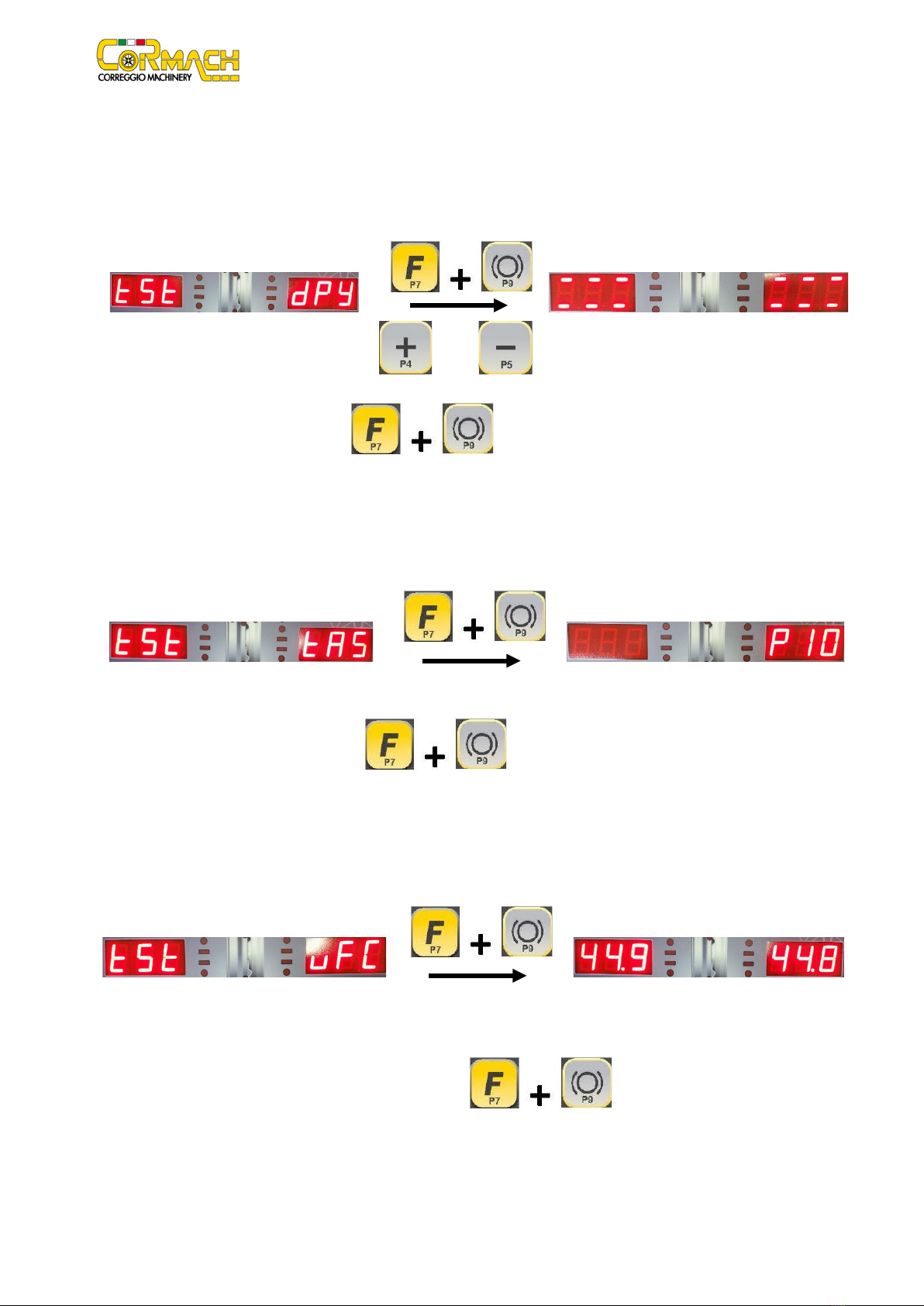
dPy Display Test .........................................................................................................................................................................6
tAS Keyboard Test ......................................................................................................................................................................6
uFC Converter voltage-frequency test .......................................................................................................................................6
RET Return .................................................................................................................................................................................7
CPb
ELECTROMAGNETIC BRAKE Calibration (if present) ............................................................................................................7
MCA
WHEEL GUARD MICRO SWITCH activation or deactivation...............................................................................................8
3. MENU PARAMETERS ACCESS (with password) ..........................................................................................................................9
Gau Activation or deactivation of the distance/diameter sensor ............................................................................................10
Lar Activation or deactivation of the width sensor (if present) ...............................................................................................11
Son
Activation or deactivation of the SONAR device (if present) .............................................................................................13
Las
Activation or deactivation of the LASER device (if present)................................................................................................14
Pbr Activation or deactivation of the clamping brake (if present) ...........................................................................................15
iLL Activation or deactivation of the illumination LEDs (if present) .........................................................................................16
SPn Revolution counter reset (spin).........................................................................................................................................17
ShF Shaft unit static imbalance measurement.........................................................................................................................17
4. PICK-UP SPRING PRE-CHARGE REGULATION............................................................................................................................18
5. ACQUISITION DEVICES CALIBRATION MENU ...........................................................................................................................19
DIS Distance Sensor..................................................................................................................................................................19
DIA Diameter sensor calibration ..............................................................................................................................................21
LAR Width sensor calibration (if present) ................................................................................................................................23
SON
SONAR device calibration (if present)...............................................................................................................................24
RET Return ...............................................................................................................................................................................25
6. MACHINE CALIBRATION...........................................................................................................................................................26
6.1 When to carry out machine calibration .................................................................................................................................26
6.2 Machine calibration for the CAR/SUV Wheel Type................................................................................................................26
6.3 Machine calibration for the MOTO wheel type .....................................................................................................................28
How to exit the MOTO wheel type calibration ............................................................................................................................30
7. ERROR CODES AND WARNINGS ...............................................................................................................................................30
8. ACOUSTIC SIGNALS ..................................................................................................................................................................33
9. SPECIAL VISUAL SIGNALS .........................................................................................................................................................33
10. TROUBLESHOOTING...............................................................................................................................................................34
11. WIRING DIAGRAM..................................................................................................................................................................35
The MANUFACTURER reserves the right to make any change to products in order to improve them.
The MANUFACTURER reserves the right to make any change to this manual without notice.

Technical Support Manual – 05/2018 Rel. 2.1.3 Page 2
1. SERVICE MODE
The machine can run in two different modes:
•NORMAL Mode: this mode is pre-set upon activation of the machine and allows the wheels to be balanced.
•SERVICE Mode: principally, this mode refers firstly to the SERVICE technical personnel and secondly to the end user.
In SERVICE mode, several options are available to configure, calibrate, and test the machine. Some of these options can be accessed
by pressing a key, whereas other options are available in the menus.
2. TEST PROGRAM MENU ACCESS
The machine is provided with a series of TEST programs that can be used to detect any anomaly. The TEST programs are grouped
inside the "Test Programs" menu.
Figure F2.1: Machine use controls
Table T2.1: Settings, programmes and Menu available in the SERVICE mode
SERVICE mode
Key
Setting/programme or Menu
Key
Setting/programme or Menu
[P1]
Sensor calibration programming
[F+P1]
Not used
[P2]
Not used
[F+P2]
Select weight material in Fe/Zn, or Pb
[P3]
Machine calibration
[F+P3]
Exit the SERVICE mode (return to NORMAL mode)
[P4]
Select grams/ounces
[F+P4]
Read counter (nr. of Launches)
[P5]
Select inches/mm
[F+P5]
Parameters (Menu with password for technical service)
[P6]
Select the imbalances view threshold
[F+P6]
Not used
[P9]
Not used
[F+ P9]
Test Programmes
Note: keys [P7] , [P8] Start and [P10] Stop ARE NOT USED to access settings, programs or Menus.
[F+P1]
[F+P2]
[F+P3]
[F+P6]
[F+P9]
[P3]
[F+P4]
[F+P5]

Technical Support Manual – 05/2018 Rel. 2.1.3 Page 3
To access the "TEST Programs" Menu, proceed as follows (See Figure F2.1):
1. Enter the SERVICE mode by pressing [F+P3] ;
2. Press keys [F+P9] to access the “TEST Programs” Menu;
3. Browse the list of the Menus with keys [P4] or [P5] until the option required is displayed. The options
available are listed in table T2.2;
Table T2.2: "TEST" Menu Options
Options
Description
Notes
ENC
ENCODER disc reading test
rPM
Shaft rotation speed test
SiG Pick-up signal test It also controls the
parameters that
influence the signal
dPy
Displays and LED test
uFC
Converter voltage-frequency test
CPb
Electromagnetic brake calibration (if present)
MCA
Wheel guard micro switch activation/deactivation
Ret
Return to SERVICE mode
4. Press keys [F+P9] to confirm the option;
5. To exit the “TEST Programs” Menu, select the Menu option Ret and press keys [F+P9] .
ENC
ENCODER disc test
This menu option allows you to run the ENCODER disc test. When you access this option, the display shows the message Enc 000
as shown in figures F2.2 and F2.3.
Figure F2.2: ENCODER disc test message
Figure F2.3: ENCODER disc value message
Manually turn the wheel and check that values from 000 to 255 (from 000 to 255 turning clockwise and from 255 to 000 turning anti-
clockwise) are displayed. When the reset "tooth" of the encoder disc is in position H12, the value displayed must be 000 (or it must
be reset to 000 should the value be different).
If the count is not correct, check and/or adjust the mechanical fixing of the DEB board. Check the cable if there are no mechanical
problems. To exit the ENCODER disc test, press [F+P9] .

Technical Support Manual – 05/2018 Rel. 2.1.3 Page 4
RPM
Shaft rotation speed test
This menu option allows you to run the shaft rotation speed test. When you access this option, the display shows the message RPM
000 as shown in figures F2.4 and F2.5.
Figure F2.4: Shaft rotation speed test message
Figure F2.5: Shaft rotation value message
To perform a realistic measurement, we recommend mounting a medium size wheel on the shaft.
Press the key [P8] or lower the wheel guard to rotate the wheel. Once the rotation is complete, the display shows the
rotation speed in RPM (revolutions per minute). You can repeat the rotation any time you wish.
The nominal rotation speed is indicated in annex 1.
If the rotation speed is considerably lower than that indicated, make sure that the main power voltage does not drop excessively
during rotation.
If the main power voltage is correct, check the tension of the belt.
If the tension of the belt is correct, check the motor and PWRB board.
NOTE: the rotation speed also depends on the main power supply frequency. The nominal rotation speed indicated in table T10.2
refers to a frequency of 50 Hz. If the frequency in that country is 60 Hz, the rotation speed will be 20% higher (provided that the motor
and pulley are the same).
To exit the rotation speed test, press [F+P9] .
SIG
Pick-up signals test
This menu option allows you to run the pick-up signals test. When you access this option, the display shows the message SIG SIG
as shown in figures F2.6 and F2.7.
Figure F2.6: Pick-up signal test message
Figure F2.7: Pick-up signal message
Use a well-balanced wheel weighing 50 grams outside to run this test. The dimensions of the wheel should be:
•Diameter: 15”
•Width: 6”
If the dimensions of the wheel are different from those indicated, the pick-up signals detected will be different when compared to
those stated in table T10.2.
The pick-up signals depend on the diameter and width of the wheel (the greater the diameter, the higher the signal and the greater
the width, the higher the signal).
Press the key [P8] or lower the wheel guard to perform the launch. During rotation, the display shows a sequence of
three measurements performed at different attenuation levels. This sequence will be repeated until the wheel stops rotating, by
pressing [P10] or by lifting the wheel guard.

Technical Support Manual – 05/2018 Rel. 2.1.3 Page 5
Table T2.3: Pick-up signal measurement sequence
Display
Description
Notes
Att1
Attenuation set to 1 (i.e. no attenuation)
AAA BBB AAA = pick-up signal A
BBB = pick-up signal B
Values AAA and BBB must not differ excessively.
Att2
Attenuation set to 2
AAA BBB AAA = pick-up signal A
BBB = pick-up signal B
Values AAA and BBB should be similar to those of
measurement Att1
Att4
Attenuation set to 4
AAA BBB AAA = pick-up signal A
BBB = pick-up signal B
Values AAA and BBB should be close to those of
measurement Att1
The values of the signals displayed are expressed in an internal numerical format and they do not correspond to any international
unit of measurement.
The attenuator circuit adjusts the pick-up signals so as not to saturate the input stage of the CPU-C1C.X board, which provides
negative results. It is used to balance heavy wheels (e.g. the wheels of a lorry) and, even if provided, it should not be used on balancing
machines MEC 5, MEC 10, MEC 15 and MEC 20. If both pick-up signals differ from, but are similar to the values indicated in table
T10.2 check if:
•The dimensions of the wheel are different from those of the reference wheel;
•The wheel is not balanced;
•The 50 grams of the imbalance weight are placed on the inner side;
•The imbalance weight does not exceed or drop below 50 grams;
•The regulation spring pre-charge is correct;
•Both pick-ups are original;
•The CPU-C1C.X runs properly (check this by running the VFC TEST described below).
If both pick-up signals differ considerably from the values indicated in annex 1 and from each other, check if:
•The cables of pick-ups A and B have been connected to the wrong connectors;
•The pick-up regulation spring pre-charge is correct;
•The CPU-C1X.X runs properly (check this by running the VFC TEST described below).
If only one pick-up signal differs considerably from the values indicated in table T10.2, check if:
•The cables of pick-ups A and B have been connected to the wrong connectors;
•The pick-up regulation spring pre-charge is correct;
•Both pick-ups are original;
•The CPU-C1C.X runs properly (check this by running the VFC TEST described below).
To exit the pick-up signals test, press [F+P9] .

Technical Support Manual – 05/2018 Rel. 2.1.3 Page 6
dPy
Display Test
This menu option allows you to run the 7-segment display and LED test. Once you have accessed this menu option, you can switch
the 7 different configurations of segments and LED units on and off to check their proper operation. A special configuration switches
all the 7 display segments and LED units on (See figures F2.8 and F2.9).
Figure F2.8: Display Test Message
Figure F2.9: Display value message
Browse the configurations available with keys [P4] o [P5] .
Replace the CPU-C1C.X if one or more segments fail to switch on. This is also valid for the LEDs.
To exit the Display Test program, press [F+P9] .
tAS
Keyboard Test
This menu option allows you to run the keyboard test. When you access this option, the RH display shows the message P . (See
figures F3.10 and F3.11).
Figure F3.10: Keyboard Test Message
Figure F3.11: Keyboard value message
Press one key at a time to make sure that the control corresponds to the key. For technical reasons, key [P7] (F) cannot be tested.
Key [P8] Start is displayed for a short time.
To exit the Keyboard Test program, press [F+P9] .
uFC
Converter voltage-frequency test
This menu option allows you to run the converter voltage-frequency test (or VFC) of the CPU-C1C.X board. When you access this
option, the display shows digits AAA BBB, as shown in figures F2.12 and F2.13.
Figure F2.12: VFC Test Message
Figure F2.13: VFC value message
Value AAA refers to pick-up VFC A, whereas value BBB refers to pick-up VFC B. The values displayed must be stable (operators should
not touch or knock the machine) and must range within the tolerance levels indicated in table T10.2. When the machine is touched
or knocked both VFC channels will vary and should stabilize once the mechanical disturbance is over.
To exit the voltage-frequency converter test program, press [F+P9] .

Technical Support Manual – 05/2018 Rel. 2.1.3 Page 7
RET
Return
This option allows you to return to the SERVICE mode, as shown in figures F2.14 and F2.15.
Figure F2.14: Return message
Figure F2.15: SERVICE mode message
CPb
ELECTROMAGNETIC BRAKE Calibration (if present)
Description
1
Enter the SERVICE mode by pressing [F+P3]
.
2
Press [F+P9] to
enter in “TEST Programs” menu.
3 Browse the list of the Menus with keys [P4]
or [P5] until the option
required is displayed. Press [F+P9]
to confirm the
option.
4
Press [F+P9] to
confirm the option.
5 Lower the wheel guard: the machine will run
some launches. 1.
2.
3.
4.
6
To exit the ELECTROMAGNETIC BRAKE
CALIBRATION program press [F+P9]
.
7
To exit the “TEST programs” Menu press
[F+P9] .

Technical Support Manual – 05/2018 Rel. 2.1.3 Page 8
MCA
WHEEL GUARD MICRO SWITCH activation or deactivation
Description
1
Enter the SERVICE mode by pressing [F+P3]
.
2
Press [F+P9] to
enter in “TEST Programs” menu.
3 Browse the list of the Menus with keys [P4]
or [P5] until the option
required is displayed.
Press [F+P9]
to confirm the
option.
4
Press [F+P9] to
DEACTIVATE THE WHEEL GUARD MICRO
SWITCH. In this way it is possible to run a
launch by pressing the key START [P8]
with the wheel guard raised.
5
Press [F+P9] to
ACTIVATE THE WHEEL GUARD MICRO
SWITCH again.
6 To exit the WHEEL GUARD MICRO SWITCH
ACTIVATION program press [F+P9]
.
7 To exit the “TEST programs” Menu press
[F+P9] .

Technical Support Manual – 05/2018 Rel. 2.1.3 Page 9
3. MENU PARAMETERS ACCESS (with password)
The machine must be configured to enable the electronic control unit (CPU-C1C.X) to receive communications from the installed
devices. The configuration is executed via the parameters MENU, available in SERVICE mode. The Parameters MENU allows you to
run various operations reserved to technical personnel, such as re-setting the revolution counter - SPIN. Proceed as follows:
1. Enter the SERVICE mode by pressing [F+P3] ;
2. Press the keys [F+P5] to access the Parameters MENU;
3. A password is required to enter this menu. Enter the password by pressing the keys in the sequence indicated within 5
seconds, or the machine will return to SERVICE mode:
a) [P1]
b) [P4]
c) [P2]
d) [P5]
The password must not be disclosed to the end user, as he/she may accidentally modify the machine configuration;
4. Browse the list of the menus with keys [P4] or [P5] until the option required is displayed. The menu
options available are listed in table T3.1;
Table T3.1: Parameters Menu Option
Options
Description
Notes
GAU
Activate or deactivate the distance/diameter sensor
Default status: Deactivated
LAR
Activate or deactivate the width sensor
Default status: Deactivated
Pbr
Activate or deactivate the clamping brake
Default status: Deactivated
iLL
Activate or deactivate the automatic switch-on of the illumination LEDs
Default status: Deactivated
Son
Activate or deactivate the SONAR device
Default status: Deactivated
Las
Activate or deactivate the LASER device
Default status: Deactivated
SPn
Reset the revolution counter
ShF
Measure the static imbalance of the shaft unit
Ret
Return to SERVICE mode
5. Press keys [F+P5] to confirm the option;
6. Some programs require additional confirmation to continue (the flashing message yEs is displayed). Press keys [F+P5]
to confirm or any other key to cancel;
7. To exit the Parameters Menu, select option Ret and press keys [F+P5] .

Technical Support Manual – 05/2018 Rel. 2.1.3 Page 10
Gau
Activation or deactivation of the distance/diameter sensor
This menu option allows you to activate or deactivate the distance-diameter sensor. This is a double function: if the function is
disabled, press [F+P5] to enable it and vice-versa.
Description
1
Enter the SERVICE mode by pressing [F+P3]
.
2
Press [F+P5] to
enter in PARAMETERS MENU.
3 A password is required to enter this menu.
Enter the password by pressing the keys in
the sequence indicated within 5 seconds, or
the machine will return to SERVICE mode:
1. [P1]
2. [P4]
3. [P2]
4. [P5]
4
Press [F+P5] to
activate the
DISTANCE/DIAMETER SENSOR
GAUGE. The DISTANCE/DIAMETER SENSOR
GAUGE IS ENABLED.
5
Press [F+P5] to
deactivate
DISTANCE/DIAMETER SENSOR
GAUGE.
6 To exit the Parameters Menu, select option
Ret and press [F+P5]

Technical Support Manual – 05/2018 Rel. 2.1.3 Page 11
Lar
Activation or deactivation of the width sensor (if present)
When present, the external sensor must be installed according to the pictures provided below.
Remove external sensor from the packaging.
There are holes at the back of the wheel balancer to attach the external sensor. Place the flange of external sensor on the three
holes.
Square the external sensor using a level. Tighten the 3 M6 screws.
Connect the cable of the external sensor to the machine and screw on the connector.

Technical Support Manual – 05/2018 Rel. 2.1.3 Page 12
To activate or deactivate the width sensor, proceed as follow.
Description
1
Enter the SERVICE mode by pressing [F+P3]
.
2
Press [F+P5] to
enter in PARAMETERS MENU.
3 A password is required to enter this menu.
Enter the password by pressing the keys in
the sequence indicated within 5 seconds, or
the machine will return to SERVICE mode:
1. [P1]
2. [P4]
3. [P2]
4. [P5]
4 Browse the list of the menus with [P4]
or [P5] until the option
required is displayed.
5
Press [F+P5] to
activate the WIDTH SENSOR GAUGE. The
WIDTH SENSOR GAUGE IS ENABLED. To
deactivate the WIDTH SENSOR GAUGE press
again [F+P5] .
6 To exit the Parameters Menu, select option
Ret and press [F+P5]
.
The deactivation of the width sensor has no effect on the automatic acquisition of distance and diameter.

Technical Support Manual – 05/2018 Rel. 2.1.3 Page 13
Son
Activation or deactivation of the SONAR device (if present)
Description
1
Enter the SERVICE mode by pressing [F+P3]
.
2
Press [F+P5] to
enter in PARAMETERS MENU.
3
A password is required to enter this menu.
Enter the password by pressing the keys in
the sequence indicated within 5 seconds, or
the machine will return to SERVICE mode:
1. [P1]
2. [P4]
3. [P2]
4. [P5]
4 Browse the list of the menus with [P4]
or [P5] until the option
required is displayed.
5
Press [F+P5] to
activate the SONAR device.
6
Press [F+P5] to
deactivate the SONAR device.
7 To exit the Parameters Menu, select option
Ret and press [F+P5]
.

Technical Support Manual – 05/2018 Rel. 2.1.3 Page 14
Las
Activation or deactivation of the LASER device (if present)
Description
1
Enter the SERVICE mode by pressing [F+P3]
.
2
Press [F+P5] to
enter in PARAMETERS MENU.
3
A password is required to enter this menu.
Enter the password by pressing the keys in
the sequence indicated within 5 seconds, or
the machine will return to SERVICE mode:
1. [P1]
2. [P4]
3. [P2]
4. [P5]
4 Browse the list of the menus with [P4]
or [P5] until the option
required is displayed.
5
Press [F+P5] to
activate the LASER device.
6
Press [F+P5] to
deactivate the LASER device.
7 To exit the Parameters Menu, select option
Ret and press [F+P5]
.

Technical Support Manual – 05/2018 Rel. 2.1.3 Page 15
Pbr
Activation or deactivation of the clamping brake (if present)
Description
1
Enter the SERVICE mode by pressing [F+P3]
.
2
Press [F+P5] to
enter in PARAMETERS MENU.
3 A password is required to enter this menu.
Enter the password by pressing the keys in
the sequence indicated within 5 seconds, or
the machine will return to SERVICE mode:
1. [P1]
2. [P4]
3. [P2]
4. [P5]
4 Browse the list of the menus with [P4]
or [P5] until the option
required is displayed.
5
Press [F+P5] to
activate the ELECTROMAGNETIC BRAKE.
The ELECTROMAGNETIC BRAKE IS ENABLED.
6
Press [F+P5] to
deactivate the ELECTROMAGNETIC BRAKE.
7 To exit the Parameters Menu, select option
Ret and press [F+P5]

Technical Support Manual – 05/2018 Rel. 2.1.3 Page 16
iLL
Activation or deactivation of the illumination LEDs (if present)
This menu option allows you to automatically activate or deactivate the illumination LEDs.
This is a double function: if the function is disabled, press keys [F+P5] to enable it and vice-versa.
Description
1
Enter the SERVICE mode by pressing [F+P3]
.
2
Press [F+P5] to
enter in PARAMETERS MENU.
3 A password is required to enter this menu.
Enter the password by pressing the keys in
the sequence indicated within 5 seconds, or
the machine will return to SERVICE mode:
1. [P1]
2. [P4]
3. [P2]
4. [P5]
4 Browse the list of the menus with [P4]
or [P5] until the
option required is displayed.
5
Press [F+P5] to
activate the ILLUMINATION LED. The
ILLUMINATION LED IS ENABLED.
6
Press [F+P5] to
deactivate the ILLUMINATION LED.
7 To exit the Parameters Menu, select option
Ret and press [F+P5]
.

Technical Support Manual – 05/2018 Rel. 2.1.3 Page 17
SPn
Revolution counter reset (spin)
This menu option allows you to reset the machine revolution counter.
Figure F3.5: Revolution counter reset message
Confirm to reset the revolution counter (the LH display will show yEs). Press the keys [F+P5] to confirm or
any other key to cancel the operation.
The revolution counter counts only the revolutions performed in NORMAL mode. A manually blocked revolution (using the STOP key
or the wheel guard) will not be counted.
ShF
Shaft unit static imbalance measurement
This menu option allows you to measure the static imbalance of the shaft unit. The shaft unit includes the shaft, flange, hub, and
pulley.
Figure F3.6: Static imbalance measurement message
Figure F3.7: Static imbalance value message
Due to mechanical imperfections, each shaft unit has a small static imbalance (a few grams). The effect of this small static imbalance
is measured during the Cal0 calibration phase of the machine and it is subtracted at every balancing cycle. Therefore, mechanical
balancing is not required for the shaft unit. However, you can use this program to identify the exact value of this static imbalance.
Proceed as indicated below:
1. Access the measurement option of the shaft unit static imbalance by pressing [F+P5] ;
2. The display will show the static imbalance saved in eeprom during the previous measurement. If the electronic board is
blank, the value will be XXX;
3. Remove the wheel and any other accessory from the shaft;
4. Press key [P8] . Once the revolution is complete, the machine will show the static imbalance of the shaft unit.
The static imbalance is always indicated in grams.

Technical Support Manual – 05/2018 Rel. 2.1.3 Page 18
4. PICK-UP SPRING PRE-CHARGE REGULATION
Equipment required: 6 mm hex wrench
To function properly, the pick-up must be pre-charged with a spring. In order to do so, the spring must be compressed with a screw
according to that described below:
1. ALL PROCEDURES (INCLUDING MINOR) MUST BE CARRIED OUT BY QUALIFIED STAFF;
2. BEFORE PERFORMING ANY PROCEDURE, DISCONNECT THE ELECTRICAL POWER SUPPLY;
3. Manually tighten the hex screw until it stops;
4. Repeat step 1 for the other pick-up;
5. Make sure that the springs and hex screws are perpendicular to the pick-up support unit. If required, loosen the screw, turn
the spring (or invert it) and repeat steps 1 and 2 until you obtain perpendicularity;
6. Tighten the screws of the two pick-ups by turning three times. It is good practice to perform one turn at a time, alternating
the two pick-up springs. See figure F4.1;
7. Calibrate the machine.
IMPORTANT: Each time a pick-up is tightened or loosened, the machine MUST always be calibrated.
Figure F4.1: Pick-up spring pre-charge regulation
3 turns
This manual suits for next models
3
Table of contents
Other Cormach Wheel Balancer manuals

Cormach
Cormach GEO 10 User manual

Cormach
Cormach GEO 15 User manual

Cormach
Cormach MEC 1 Installation instructions

Cormach
Cormach MEC 810VD-VDL-VDBL User manual

Cormach
Cormach MEC 200 TRUCK User manual

Cormach
Cormach TOUCH MEC 1000 SONAR Installation instructions

Cormach
Cormach GEO 15 User manual

Cormach
Cormach TOUCH MEC 100 User manual

Cormach
Cormach MOTO MEC User manual