Ravaglioli RAVTD1760 WS User manual

Instruction manual
RAVAGLIOLI S.p.A.
RAVTD1760 WS – RAVTD1780 WS
Code M0197 - rev.1.0
(11/2010)
RAVAGLIOLI S.p.A. - Via I° Maggio, n° 3 (Pontecchio Marconi)
40037 Sasso Marconi (Bologna - Italy)
Tel. 051/ 67.81.511 – Fax 051/ 84.64.67 E-mail: [email protected]
COMPOSIZIONE COMPOSITION ZUSAMMENSETZUNG COMPOSITION COMPOSICIÓN
54 pagine (copertine
comprese)
54 pages (including
cover pages)
54 Seiten (inkl.
Deckblätter)
54 pages (pages de la
couverture incluses)
54 páginas (incluidas
las portadas)
52 pagine numerate 52 numbered pages 52 numerierte Seiten 52 pages numérotées 52 páginas numeradas
• Per eventuali chiarimenti interpellare il più vicino rivenditore oppure rivolgersi direttamente a:
• For any further information please contact your local dealer or call:
• Im Zweifelsfall ober bei Rückfragen wenden Sie sich bitte an den nächsten Wiederverkäufer oder direkt an:
• Pour tout renseignement complémentaire s’adresser au revendeur le plus proche ou directement à:
• En caso de dudas, para eventuales aclaraciones, póngase en contacto con el distribuidor más próximo ó
diríjase directamente a:
RAVTD1760 WS – RAVTD1780 WS
MANUALE DI ISTRUZIONE
INSTRUCTION MANUAL
BETRIEBSANLEITUNG
MANUEL D’INSTRUCTIONS
MANUAL DE INSTRUCCIONES

Instruction manual
RAVAGLIOLI S.p.A.
RAVTD1760 WS – RAVTD1780 WS
Code M0197 - rev.1.0
(11/2010)
RAVAGLIOLI S.p.A. - Via I° Maggio, n° 3 (Pontecchio Marconi)
40037 Sasso Marconi (Bologna - Italy)
Tel. 051/ 67.81.511 – Fax 051/ 84.64.67 E-mail: [email protected]
SYMBOLS USED IN THE MANUAL
SIMBOLI SYMBOLS ZEICHEN SYMBOLES SÍMBOLOS
VIETATO!
FORBIDDEN!
VERBOTEN INTERDIT! PROHIBIDO!
Obbligo!
Operazioni o
interventi da
eseguire
obbligatoriamente
Mandatory!
Operations or
jobs to be
performed
compulsorily
Vorschirift
Obligatorisch
auszuführende
Arbeitsvorgänge
oder Eingriffe
Obligation.
Opérations ou
interventions
obligatoires
Obigación.
Operaciones o
intervenciones que
hay que realizar
obligatoriamente
Pericolo!
Prestare
particolare
attenzione
Hazard!
Be especially
careful
Gefahr!
Äusserste
Vorsicht ist
geboten
Dager!
Faire trés
attention
Peligro!
Prestar especial
atención

Instruction manual
RAVAGLIOLI S.p.A.
RAVTD1760 WS – RAVTD1780 WS
Code M0197 - rev.1.0
(11/2010)
RAVAGLIOLI S.p.A. - Via I° Maggio, n° 3 (Pontecchio Marconi) Page 1/52
40037 Sasso Marconi (Bologna - Italy)
Tel. 051/ 67.81.511 – Fax 051/ 84.64.67 E-mail: [email protected]
CONTENTS
0CAUTION ................................................................................................................................................ 3
0.1 Preliminary Safety Information ............................................................................................................ 3
1INTENDED USE ..................................................................................................................................... 4
2OPERATOR TRAINING ....................................................................................................................... 4
2.1 General Preventive Measures ............................................................................................................... 4
3MACHINE COMPOSITION ................................................................................................................. 5
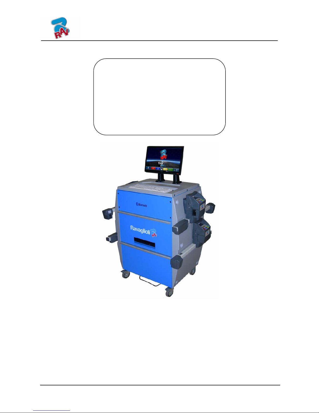
3.1 Models RAVTD1780WS – RAVTD1760WS Composition ................................................................ 5
3.2 Safety Devices ...................................................................................................................................... 6
3.3 Measurement Range and Accuracy ...................................................................................................... 6
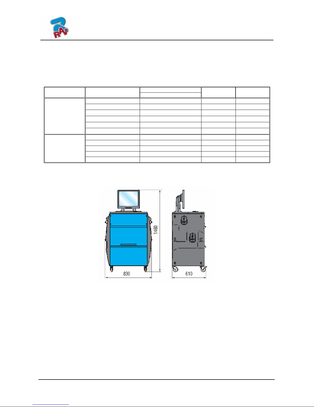
3.4 Overall Dimensions .............................................................................................................................. 6
3.5 Managing PC ........................................................................................................................................ 6
3.6 Detectors............................................................................................................................................... 7
3.6.1 Front Detectors............................................................................................................................................... 8
3.6.2 Rear Detectors RAV TD1780WS..................................................................................................................... 8
3.6.3 Rear Detectors RAV TD1760WS..................................................................................................................... 8
3.6.4 Detector Keypads............................................................................................................................................ 9
3.6.5 LED indicating Levelling and Tolerance during Adjustment.......................................................................... 9
3.7 Clamps................................................................................................................................................ 10
3.7.1 Clamps STDA33............................................................................................................................................ 10
3.7.2 Clamps STDA34............................................................................................................................................ 10
3.7.3 Clamps STDA35............................................................................................................................................ 11
3.7.4 Clamps STDA46............................................................................................................................................ 11
3.8 Rotating Plates.................................................................................................................................... 12
3.8.1 Rotating Plates S110A7 ................................................................................................................................ 12
3.8.2 Electronic Rotating Plates Connected to Detectors with STDS43 Via Radio Transmission......................... 12
4SWITCHING THE MACHINE ON AND OFF.................................................................................. 13
4.1 Switching the Machine On ................................................................................................................. 13
4.2 Switching the Machine Off................................................................................................................. 13
5DETECTORS AUTOMATIC SWITCHING OFF............................................................................. 15
6FLAT BATTERY INDICATION.........................................................................................................15
7PROGRAMME CONFIGURATION .................................................................................................. 16
7.1 DATABASE Groups Configuration...................................................................................................17
8VEHICLE DIAGNOSIS AND ADJUSTMENT ................................................................................. 19
8.1 Introduction Page................................................................................................................................ 19
8.2 Vehicle Make and Model Selection.................................................................................................... 19
8.3 Selected Vehicle Technical Specification Displaying ........................................................................ 22
8.4 Preliminary Operations....................................................................................................................... 23
8.4.1 Vehicle Check Preliminary Operations......................................................................................................... 23
8.4.2 Run-Ou Preparation ..................................................................................................................................... 23
8.5 Run-Out .............................................................................................................................................. 24
8.5.1 Run-Out with Raised Wheels......................................................................................................................... 24
8.5.2 Thrust Run-Out with Automatic Acquisition ................................................................................................. 27
8.5.1 Inclinometer-controlled Run-Out.................................................................................................................. 29
8.6 Measurement Preliminary Operations ................................................................................................ 32
8.7 Detectors Alignment and Levelling.................................................................................................... 33
8.8 Steering Procedure.............................................................................................................................. 34
8.9 Vehicle Diagnosis............................................................................................................................... 35
8.10 Adjustment Preliminary Operations ................................................................................................... 36
8.11 Rear Axle Adjustment ........................................................................................................................ 36

Instruction manual
RAVAGLIOLI S.p.A.
RAVTD1760 WS – RAVTD1780 WS
Code M0197 - rev.1.0
(11/2010)
Page 2/52 RAVAGLIOLI S.p.A. - Via I° Maggio, n° 3 (Pontecchio Marconi)
40037 Sasso Marconi (Bologna - Italy)
Tel. 051/ 67.81.511 – Fax 051/ 84.64.67 E-mail: [email protected]
8.12 Front Axle Adjustment ....................................................................................................................... 37
8.13 Additional Functions Menu ................................................................................................................ 38
8.14 Printout of Measurements taken ......................................................................................................... 39
9DATABASE CUSTOMISATION ........................................................................................................ 42
9.1 New Group Entry................................................................................................................................ 42
9.2 New Group Deletion........................................................................................................................... 43
9.3 New Vehicle Entry ............................................................................................................................. 44
9.4 Customised Vehicle Deletion ............................................................................................................. 47
10 PROGRAMME AND DATABASE PROTECTION SMART CARD.............................................. 48
10.1 DATABASE Management ................................................................................................................. 48
11 DETECTORS' ERRORS ...................................................................................................................... 50
11.1 Data Reception/Transmission Error between Detectors and Cabin.................................................... 50
11.2 Angle Measurement Horizontal Error ................................................................................................ 50
12 TROUBLES............................................................................................................................................ 51
13 MAINTENANCE................................................................................................................................... 51
14 STORAGE AND SCRAPPING............................................................................................................ 52
15 MACHINE IDENTIFICATION DATA .............................................................................................. 52

Instruction manual
RAVAGLIOLI S.p.A.
RAVTD1760 WS – RAVTD1780 WS
Code M0197 - rev.1.0
(11/2010)
RAVAGLIOLI S.p.A. - Via I° Maggio, n° 3 (Pontecchio Marconi) Page 3/52
40037 Sasso Marconi (Bologna - Italy)
Tel. 051/ 67.81.511 – Fax 051/ 84.64.67 E-mail: [email protected]
Bluetooth brands are property of their owners, and are used by
RAVAGLIOLI S.p.A under license.
0 CAUTION
Any damage caused by failure to follow the instructions in this manual or improper
machine use shall relieve RAVAGLIOLI S.p.A. of all liability.
0.1 Preliminary Safety Information
Before starting the machine:
•Read the instructions and the entire manual before using or working on the wheel aligner.
This manual represents an integral part of the product and is intended to inform the user
on how to use the RAVTD1760WS and RAVTD1780WS wheel aligner. Keep the manual for
the entire life of the machine. Keep it in an easy to access place and refer to it every time
the need arises. All machine operators must be able to read the manual.
•Make sure the power supply is in conformity with the specifications shown on the plate.
Voltage and frequency data plate is positioned on machine back side. Please, read plate
data. NEVER connect aligner to a voltage or frequency other than the specified ones.
•Duly arrange wheel aligner power cable. This product features a 3-wire plug with built-in
grounding. It can be plugged into a socket with built-in grounding, only. Should a
grounded socket not be available for machine connection, contact an electrician. Do not
tamper with or misuse plug.
Upon machine switching off:
•Do not switch off the built-in PC by unplugging it or by turning PC switch to off, but
follow the procedure set forth in par.4.2 on page 13. PC wrong switching off could lead to
HARD-DISK files "corruption".
•The switching off procedure set forth in par. 4.2 on page 13 does not affect detector
recharge supports, which continue being powered.
In emergency conditions and before performing any maintenance:
•Insulate the machine against any power source using the special master switch, and
remove plug from power socket.
•Do not try to service this unit arbitrarily, as the opening or removal of machine doors
could expose user to hazardous voltage. Maintenance operations shall be carried out by
authorised service personnel, only.
Work environment and machine cleaning:
•The work environment must be kept clean and dry, and must not be exposed to
atmospheric agents. It must also be well lit.
•Do not clean the machine using jets of water and compressed air.
To clean plastic panels or surfaces use a moist cloth (avoid using liquids containing
solvents).
RAVAGLIOLI S.p.A. shall be entitled to make any changes to the models described in this
manual at any time for reasons of a technical and commercial nature.

Instruction manual
RAVAGLIOLI S.p.A.
RAVTD1760 WS – RAVTD1780 WS
Code M0197 - rev.1.0
(11/2010)
Page 4/52 RAVAGLIOLI S.p.A. - Via I° Maggio, n° 3 (Pontecchio Marconi)
40037 Sasso Marconi (Bologna - Italy)
Tel. 051/ 67.81.511 – Fax 051/ 84.64.67 E-mail: [email protected]
1 INTENDED USE
RAVTD1760WS and RAVTD1780WS systems are machines for the detection of all vehicle
special angles.
Angles are detected by four detectors with microprocessor technology and infrared
measurement system, and data transmission (without any cable connection between
detectors).
The data of front cabin detectors are transmitted VIA RADIO through modules
.
Vehicle max. allowed wheelbase length for data transmission and angle measurement is 4.5
m.
Machine operational temperature range: 0 to 40°C.
2 OPERATOR TRAINING
The machine must be used by specifically trained and authorised personnel, only. To ensure
proper machine use and that measurements can be efficiently taken, operators must be correctly
trained and acquire the skills consistent with the instructions provided by the manufacturer. In
case of any doubts relating to machine use and maintenance, refer to the instruction manual and
then, if such doubts persist, contact an authorised after-sales centre or RAVAGLIOLI S.p.A.
technical assistance directly.
2.1 General Preventive Measures
•During operation and maintenance of this machine, always abide by the safety and
accident-prevention regulations in force.
•The machine must only be used by adequately trained and authorised persons.
•This machine must only be used for the purpose for which it was expressly intended.
RAVAGLIOLI S.p.A. declines all liability for injury or damage to persons animals and
things caused by improper machine use.
•Accessories and spare parts must be fitted by persons authorised by RAVAGLIOLI
S.p.A. and only original spare parts and accessories must be used.
•The machine must only be operated in places where there is no danger of explosions
or fire.
•Removal or changes made to safety devices, or warning signals on the machine can
cause serious hazards and represent a violation of European safety regulations.
•Before doing any maintenance jobs on the system, always disconnect the power
supply.
In case of doubt, do not interpret, but contact RAVAGLIOLI S.p.A. technical
assistance in order to obtain instructions suitable for performing operations in total
safety.
•Do not allow unauthorised personnel to come near the wheel aligner during use.

Instruction manual
RAVAGLIOLI S.p.A.
RAVTD1760 WS – RAVTD1780 WS
Code M0197 - rev.1.0
(11/2010)
RAVAGLIOLI S.p.A. - Via I° Maggio, n° 3 (Pontecchio Marconi) Page 5/52
40037 Sasso Marconi (Bologna - Italy)
Tel. 051/ 67.81.511 – Fax 051/ 84.64.67 E-mail: [email protected]
3 MACHINE COMPOSITION
3.1 Models RAVTD1780WS – RAVTD1760WS Composition
MEASUREMENT CABIN
A measurement cabin is used for all
measurement operations. This cabin also
features the electronic components necessary
for the processing and management of the
readings made by detectors .
Power supply: 220 / 240 Vac single phase
50/60Hz
PC KEYBOARD
Machine features a 102-key, PC-type command
keyboard. Function keys allow using almost all
machine functions. Vehicle general data,
customer data, and vehicle database
customisation can also be entered via PC
keyboard.
MONITOR
All models feature a 19'', 16/9, high-
definition, colour monitor. Monitor use and
maintenance instructions can be found on
the manual coming with the monitor itself.
Comply with these instructions.
PRINTER CENTRAL
COMPARTMENT
Results are printed with a inkjet colour
printer for A4 size sheets. Printer use
and maintenance instructions can be
found on the manual coming with the
printer itself. Comply with these
instructions.
MANAGING PC UPPER
COMPARTMENT
For PC characteristics
see par. 3.5 page 7
DETECTORS
POSITIONED ONTO
RECHARGE SUPPORTS
See par. 3.6 page 8
MACHINE MASTER SWITCH
CLAMPS
See par. 3.7 page 11
STEERING LOCK is a tool used to
keep vehicle steering
in a fixed position. It is used
before the adjustment
procedure, as shown by the
instructions
displayed during
programme.
PEDAL DEPRESSOR is a tool used to lock brake
pedal during measurement preliminary operations. It
has to be used as shown in the instructions displayed
during programme.
ROTATING PLATES
See par. 3.8 page 13
POWER SOCKET
SHOCK HAZARD

Instruction manual
RAVAGLIOLI S.p.A.
RAVTD1760 WS – RAVTD1780 WS
Code M0197 - rev.1.0
(11/2010)
Page 6/52 RAVAGLIOLI S.p.A. - Via I° Maggio, n° 3 (Pontecchio Marconi)
40037 Sasso Marconi (Bologna - Italy)
Tel. 051/ 67.81.511 – Fax 051/ 84.64.67 E-mail: [email protected]
3.2 Safety Devices
Wheel aligner features a safety device (master switch) positioned on the rear of the machine,
see chap. 3 on page 5. Master switch cuts off machine power when set to “0”.
3.3 Measurement Range and Accuracy
Accuracy
Axle Measurement
Measurement
Range
Measurement
Total Range
Toe ±2’ ±2° ±20° x 2
Partial toe ±1’ ±1° ±20°
Set-back ±2 ±2° ±5°
Camber ±2’ ±3° ±10°
Caster ±5’ ±10° ±18°
Front
Kingpin ±5’ ±10° ±18°
Toe ±2’ ±2° ±20° x 2
Partial toe ±1’ ±1° ±20°
Set-back ±2’ ±2° ±5°
Camber ±2’ ±3° ±10°
Rear
Thrust angle ±2’ ±2° ±5°
3.4 Overall Dimensions
Figure 1
3.5 Managing PC
Software is installed on managing PC (personal computer), positioned inside cabin.
Managing PC features:
•Processor 1.6GHz.
•RAM 1 Gb;
•Smart card reader
•4 USB; 1 LAN Ethernet 10/100Mb;
•PS2 keyboard and mouse input; Windows XP Embedded Standard 2009™ operating system,
in English language
•1366x768 Pixels HD Ready video output
•Hard Disk ≥160 Gb
RAVTD1780WS – RAVTD1760WS

Instruction manual
RAVAGLIOLI S.p.A.
RAVTD1760 WS – RAVTD1780 WS
Code M0197 - rev.1.0
(11/2010)
RAVAGLIOLI S.p.A. - Via I° Maggio, n° 3 (Pontecchio Marconi) Page 7/52
40037 Sasso Marconi (Bologna - Italy)
Tel. 051/ 67.81.511 – Fax 051/ 84.64.67 E-mail: [email protected]
3.6 Detectors
Detectors assembled on RAVTD1760WS and RAVTD1780WS do not need any cable or cord
connection for angle measurement.
Detecting units consist of infrared data transmitters/receivers and CCD-type transducers
with infrared emitter focal point.
All the characteristic angles of vehicle axles are controlled with 8 CCD sensors and infrared
transmission.
Data transmission among infrared detectors is effective also under critical lighting
conditions.
Data are transmitted from front detectors VIA RADIO through modules
located inside front detectors and cabin.
Rear detectors do not communicate directly with cabin: their data are transmitted/received
through front detectors, via infrared ray transmission.
Power is supplied by rechargeable 6V long-lasting batteries. Front and rear detectors are
recharged thanks to the supports for batteries recharge positioned onto cabin.
For all detectors with rechargeable batteries, power supply and consumption data are the
following:
REAR DETECTORS
FRONT DETECTORS
Power supply Lead battery 6V - 3.3Ah Lead battery 6V - 3.3Ah h
Average operation
with fully effective
and charged battery
Approx. 12 hours Approx. 10 hours
Average recharge
time Approx. 10 hours Approx. 10 hours

Instruction manual
RAVAGLIOLI S.p.A.
RAVTD1760 WS – RAVTD1780 WS
Code M0197 - rev.1.0
(11/2010)
Page 8/52 RAVAGLIOLI S.p.A. - Via I° Maggio, n° 3 (Pontecchio Marconi)
40037 Sasso Marconi (Bologna - Italy)
Tel. 051/ 67.81.511 – Fax 051/ 84.64.67 E-mail: [email protected]
BATTERY
COMPARTMENT
3.6.1 Front Detectors
Figure 2
3.6.2 Rear Detectors RAV TD1780WS
Figure 3
3.6.3 Rear Detectors RAV TD1760WS
Figure 4
DETECTOR KEYPAD
(see par. 3.6.4 on page 10)
BATTERY
COMPARTMENT
GREEN LED indicating that
detector is under charge
RED LED indicating that detector
is on
DETECTOR PIN LOCKING
KNOB
LED for tolerance indication
(see par. 3.6.4 on page 10)
GREEN LED indicating that detector is
under charge
RED LED indicating that detector is onDETECTOR KEYPAD
(see par. 3.6.4 on page 10)
LED indicating Levelling and tolerance
(see par. 3.6.4 on page 10)
DETECTOR PIN LOCKING KNOB
BATTERY
COMPARTMENT
DETECTOR KEYPAD
(see par. 3.6.4 on page 10)
GREEN LED indicating that detector
is under charge
RED LED indicating that detector is
on

Instruction manual
RAVAGLIOLI S.p.A.
RAVTD1760 WS – RAVTD1780 WS
Code M0197 - rev.1.0
(11/2010)
RAVAGLIOLI S.p.A. - Via I° Maggio, n° 3 (Pontecchio Marconi) Page 9/52
40037 Sasso Marconi (Bologna - Italy)
Tel. 051/ 67.81.511 – Fax 051/ 84.64.67 E-mail: [email protected]
3.6.4 Detector Keypads
Figure 5
KEYS DESCRIPTION
Detector switch-on key.
If pressed at the same time, they allow detector
manual switching off.
Legend of Figure 5:
A - •Green LED on: detector battery is under charge
B - •Red LED steady on: detector is on
•Red LED flashing: detector is flat (when battery residual charge is
lower than or equal to 30%); it will turn off after
a few minutes
3.6.5 LED indicating Levelling and Tolerance during Adjustment
Detectors (see par. 3.6.1 and 3.6.2) are equipped with LED indicators for their correct
levelling and for tolerance during adjustment.
Levelling indicator
•RED LED on Ædetector is not levelled
•RED LED flashing and GREEN LED steady on Ædetector is close, but not levelled
•GREEN LED ONLY is flashing Ædetector is levelled
•RED LED flashing and GREEN LED steady on Ædetector is close, but not levelled
•RED LED on Ædetector is not levelled
Tolerance indicator during adjustment
•GREEN LED flashing Æmeasurement is within tolerance, exactly at the centre
•RED LED flashing and GREEN LED steady on Æmeasurement is within
tolerance
•RED LED on Æmeasurement is NOT within tolerance
Note: during front adjustment, if you want to observe tolerance onto LEDs, take the red selection
frame on the value you are adjusting (see 8.12 on page 37).
During rear adjustment, on the contrary, tolerance is indicated both on horizontal LEDs (toe) and
vertical LEDs (camber).
LEDs on
FRONT
detectors
Tolerance
TOE or
CAMBER or
CASTER
LEDs on
REAR
detectors
RAVTD1780WS , only
CAMBER tolerance
TOE tolerance
(A) Green LED (B) Red LED

Instruction manual
RAVAGLIOLI S.p.A.
RAVTD1760 WS – RAVTD1780 WS
Code M0197 - rev.1.0
(11/2010)
Page 10/52 RAVAGLIOLI S.p.A. - Via I° Maggio, n° 3 (Pontecchio Marconi)
40037 Sasso Marconi (Bologna - Italy)
Tel. 051/ 67.81.511 – Fax 051/ 84.64.67 E-mail: [email protected]
3.7 Clamps
Four types of clamps are available, depending on the different needs.
3.7.1 Clamps STDA33
Clamps STDA33 are of the screw-on self-centering type for 10" to 19” alloy rims, with
removable tabs.
Figure 6
3.7.2 Clamps STDA34
Clamps STDA34 are of the 3-resting point self-centering type for 10” to 19” rims, and feature
removable tabs (different types of ABS tabs are available for the different types of alloy rims).
Figure 7
KNOB
PRODS WITH
STEEL TAB
PINS FOR TAB
CONNECTION
DETECTOR PIN LOCKING KNOB
KNOB
PRODS
WITH STEEL
TAB
FLANGE FOR
DETECTOR COUPLING
FLANGE FOR
DETECTOR COUPLING
QUICK ADJUSTMENT
ON RIM DIAMETER
PINS FOR TAB CONNECTION PINS FOR TAB CONNECTION

Instruction manual
RAVAGLIOLI S.p.A.
RAVTD1760 WS – RAVTD1780 WS
Code M0197 - rev.1.0
(11/2010)
RAVAGLIOLI S.p.A. - Via I° Maggio, n° 3 (Pontecchio Marconi) Page 11/52
40037 Sasso Marconi (Bologna - Italy)
Tel. 051/ 67.81.511 – Fax 051/ 84.64.67 E-mail: [email protected]
3.7.3 Clamps STDA35
Clamps STDA35 are of the 3-resting point self-centering type for 10” to 20” rims, with
manual approach and locking unit on tyre.
Figure 8
3.7.4 Clamps STDA46
Clamps STDA46 are of the 4-resting point type for 10” to 20” rims, and feature locking units.
Figure 9
HANDLES FOR CLAMP QUICK
COUPLING TO WHEEL
KNOBS FOR CLAMP COUPLING TO
WHEEL
KNOB FOR PRODS ADJUSTMENT
ON RIM
PRODS WITH
ABS TAB
HANDLES FOR ARM
LOCKING
HANDLES FOR ARM
LOCKING
FLANGE FOR DETECTOR
COUPLING
PRODS WITH
ABS TAB
HANDLES FOR ARM
LOCKING
HANDLES FOR ARM
LOCKING
KNOBS FOR CLAMP COUPLING
TO WHEEL
DETECTOR PIN LOCKING KNOB
PINS FOR TAB
CONNECTION
HANDLES FOR CLAMP QUICK
COUPLING TO WHEEL
FLANGE FOR
DETECTOR COUPLING
PINS FOR TAB
CONNECTION PINS FOR TAB
CONNECTION

Instruction manual
RAVAGLIOLI S.p.A.
RAVTD1760 WS – RAVTD1780 WS
Code M0197 - rev.1.0
(11/2010)
Page 12/52 RAVAGLIOLI S.p.A. - Via I° Maggio, n° 3 (Pontecchio Marconi)
40037 Sasso Marconi (Bologna - Italy)
Tel. 051/ 67.81.511 – Fax 051/ 84.64.67 E-mail: [email protected]
3.8 Rotating Plates
3.8.1 Rotating Plates S110A7
Rotating plates S110A7 have a disc diameter of 250 mm, and a loading capacity of 1,000 kg.
Figure 10
3.8.2 Electronic Rotating Plates Connected to Detectors with STDS43 Via Radio
Transmission
Electronic rotating plates STDA43 have a 300 mm anti-slip disc, and a loading capacity of
1,250 kg.
They require a low rotating torque and, as they feature and encoder, provide a high
resolution.
Figure 11
UPPER PLATE WITH ANTI-
SLIP DISC
GRADUATED ROD
GRADUAL INDICATOR
UPPER PLATE WITH ANTI-
SLIP DISC
PLATE RETAINER
PLATE RETAINER
CABLE FOR CONNECTION TO
FRONT DETECTORS
(see par. 3.6.1 on page 9)

Instruction manual
RAVAGLIOLI S.p.A.
RAVTD1760 WS – RAVTD1780 WS
Code M0197 - rev.1.0
(11/2010)
RAVAGLIOLI S.p.A. - Via I° Maggio, n° 3 (Pontecchio Marconi) Page 13/52
40037 Sasso Marconi (Bologna - Italy)
Tel. 051/ 67.81.511 – Fax 051/ 84.64.67 E-mail: [email protected]
4 SWITCHING THE MACHINE ON AND OFF
WARNING: Before switching the machine on, make sure that the
SMART CARD for programme enabling and the database are in the
special reader on PC front side.
See chap. 10.
4.1 Switching the Machine On
To switch the machine on and to gain access to the programme, turn the special switch
positioned on machine back side.
Once PC initialisation is completed by Windows operating system, programme will be
automatically enabled and the introduction page will be displayed. From this page you can
enable all machine functions (see par. 8 on page 19).
Figure 12
4.2 Switching the Machine Off
From the introduction page (see par. 8 on page 19) you can switch the machine off by
selecting the corresponding key.
DETECTOR
KEYPAD
PC KEYBOARD DESCRIPTION
It enables machine
switching off procedure
request
Figure 13

Instruction manual
RAVAGLIOLI S.p.A.
RAVTD1760 WS – RAVTD1780 WS
Code M0197 - rev.1.0
(11/2010)
Page 14/52 RAVAGLIOLI S.p.A. - Via I° Maggio, n° 3 (Pontecchio Marconi)
40037 Sasso Marconi (Bologna - Italy)
Tel. 051/ 67.81.511 – Fax 051/ 84.64.67 E-mail: [email protected]
DETECTOR
KEYPAD
PC KEYBOARD DESCRIPTION
It cancels.
It goes back to the
introduction page.
(par. 8 on page19)
Final confirmation of
machine switching off
You have to wait for the following screen to be displayed:
Figure 14
Then turn the machine off with the switch positioned on machine back side.
WARNING: The switching off procedure does not affect detector recharge
supports, which continue being powered.

Instruction manual
RAVAGLIOLI S.p.A.
RAVTD1760 WS – RAVTD1780 WS
Code M0197 - rev.1.0
(11/2010)
RAVAGLIOLI S.p.A. - Via I° Maggio, n° 3 (Pontecchio Marconi) Page 15/52
40037 Sasso Marconi (Bologna - Italy)
Tel. 051/ 67.81.511 – Fax 051/ 84.64.67 E-mail: [email protected]
5 DETECTORS AUTOMATIC SWITCHING OFF
When the introduction page is displayed, system makes all detectors automatically switch off.
Detectors will anyway automatically switch off after 5 minutes approx. if no data are received
(ex. cabin is off).
It is anyway recommended to always switch detectors manually off (see par. 3.6.4 on page 9)
when they are not used.
6 FLAT BATTERY INDICATION
System displays a flat battery warning signal (Figure 15).
This signal is also visible on the detector through the flashing of start RED LED (see par.
3.6.4 on page 9).
Figure 15
When the residual charge is LOWER than or EQUAL to 30%, system displays the page of flat
battery indication (Figure 15). Detector will automatically switch off after a few minutes. Try
not to reach this condition, and charge detectors as soon as possible.
To quit the signal page, press F1 .
DETECTOR
FLAT BATTERY
INDICATION RIGHT "REAR"
DETECTOR
IS FLAT

Instruction manual
RAVAGLIOLI S.p.A.
RAVTD1760 WS – RAVTD1780 WS
Code M0197 - rev.1.0
(11/2010)
Page 16/52 RAVAGLIOLI S.p.A. - Via I° Maggio, n° 3 (Pontecchio Marconi)
40037 Sasso Marconi (Bologna - Italy)
Tel. 051/ 67.81.511 – Fax 051/ 84.64.67 E-mail: [email protected]
7 PROGRAMME CONFIGURATION
To proceed to programme configuration, select F2 from the introduction page, as
explained in par. 8.1 on page 19.
You will enter a configuration menu allowing editing the different programme characteristics
according to your needs.
Figure 16
Language selection: You can select your dialogue language among the many available ones.
Configuration: programme will display the screen of Figure 17
You can edit system parameters, database profile, specify which parts are fitted on the
machine, parts type, make a Bluetooth search to couple detectors with cabin.
Print Menu: Print can be customised by entering workshop data, selecting the type of
desired printout, and selecting the pre-set printer (if more than one printer is connected).
Backup / Restore: In order not to run the risk to lose any vehicle and customer database
data, it is recommended to create a backup copy (data saving). We recommend using a "flash
disk" USB key for this process.
Lost or deleted data can be restored if the backup operation has been carried out, thanks to
the restore procedure.
Additional functions: programme displays screen Figure 68, from which you can access
TEST or sensor Calibration applications (reserved to skilled and authorised personnel), and
the "DATABASE MANAGEMENT", see chap. 10
DETECTOR
KEYPAD
PC KEYBOARD DESCRIPTION
It goes back to the
introduction page.
(par.8.1 on page19)
It moves selection up.
It moves selection down.
It confirms selection.

Instruction manual
RAVAGLIOLI S.p.A.
RAVTD1760 WS – RAVTD1780 WS
Code M0197 - rev.1.0
(11/2010)
RAVAGLIOLI S.p.A. - Via I° Maggio, n° 3 (Pontecchio Marconi) Page 17/52
40037 Sasso Marconi (Bologna - Italy)
Tel. 051/ 67.81.511 – Fax 051/ 84.64.67 E-mail: [email protected]
7.1 DATABASE Groups Configuration
Select "GROUPS CONFIGURATION" from programme configuration page, as explained in par.
7 on page 16.
You can edit system parameters, database profile, and specify which parts are fitted on the
machine, and parts type as well.
Figure 17
DETECTOR
KEYPAD
PC KEYBOARD DESCRIPTION
It goes back to the start
configuration page.
(par.8.1 on page19)
It moves selection up.
It moves selection down.
It confirms selection.
Select “DATABASE” option, and confirm. The following screen will be displayed:
Figure 18

Instruction manual
RAVAGLIOLI S.p.A.
RAVTD1760 WS – RAVTD1780 WS
Code M0197 - rev.1.0
(11/2010)
Page 18/52 RAVAGLIOLI S.p.A. - Via I° Maggio, n° 3 (Pontecchio Marconi)
40037 Sasso Marconi (Bologna - Italy)
Tel. 051/ 67.81.511 – Fax 051/ 84.64.67 E-mail: [email protected]
DETECTOR
KEYPAD
PC KEYBOARD DESCRIPTION
It goes back toFigure 17
It moves selection up.
It hides/displays the different
Database profiles.
It moves selection up, displaying
the following profiles.
It confirms selection.
Page Figure 18 displays a list, with the different DATABASE profiles, including the MAKES of
the vehicles circulating in the different countries and regions all over the world.
Using key F5 , you can hide and/or display any profile so as to manage Database
according to your needs.
Figure 19
By selecting any group and pressing F4, you can also customise your profile by
hiding and/or displaying the available makes, with key F5
Figure 20
Hidden makes
Displayed make
Displayed groups
Hidden groups
This manual suits for next models
1
Table of contents
Other Ravaglioli Wheel Balancer manuals
Popular Wheel Balancer manuals by other brands

Central Machinery
Central Machinery 47211 Assembly and operation instructions

Atlas
Atlas 501 quick start guide

Coats
Coats Vero Series Safety, Setup, Operation & Maintenance Manual

HENNESSY INDUSTRIES
HENNESSY INDUSTRIES Coats 1100 instructions

Magneti Marelli
Magneti Marelli MM-WB1024 user manual

Weaver
Weaver W-957-40 Operation manual