BRIGHT VULTURE BP46 User manual

BP46 – VULTURE

Use and Maintenance Manual –VER. 2016-02 Page 1
CONTENTS
1.
Introduction
P.
2
2.
Intended use
P.
3
3.
General safety rules
P.
3
3.1 Safety devices
P.
3
4.
Transport and handling
P.
3
5.
Unpacking
P.
4
6.
Installation and commissioning
P.
4
6.1 Electrical connection
P.
4
7.
Installation
P.
5
8.
Use suspension
P.
5
9.
Environmental information
P.
6
10.
Technical data
P.
6
10.1 Machine dimensions
P.
6
10.2 Working range
P.
7
10.3 Presentation of the machine
P.
8
11.
Serial number plate information
P.
8
12.
Ordinary maintenance
P.
8
13.
Control panel
P.
9
13.1 Keyboard
P.
10
13.2 NORMAL, SERVICE, STAND BY operating modes
P.
11
14.
Temporary diameter and distance sensor disabling
P.
11
15.
Machine calibration
P.
12
15.1 When to carry out machine calibration
P.
12
15.2 Machine calibration for the TRUCK wheel type
P.
12
15.3 Machine calibration for the CAR/SUV wheel Types
P.
14
16.
Use of the machine in normal mode
P.
15
16.1 Program Type
P.
16
16.2 Wheel type
P.
17
16.2.1 CAR wheel type
P.
17
16.2.2 TRUCK wheel type
P.
17
16.2.3 SUV wheel type (off-road vehicles)
P.
18
16.3 Entering wheel size
P.
18
16.3.1 Manual entry of wheel dimensions for the STD and Program Types
P.
18
16.3.2 Manual entering of the wheel dimensions for ALS1, ALS2 program types
P.
19
16.3.3 Automatic acquisition of wheel dimensions for STD Program Types
P.
21
16.3.4 Automatic acquisition of the wheel dimensions for the ALS1, ALS2 program types
P.
21
16.4 Use of the special program types for ALS1 and ALS2 aluminium wheels
P.
22
16.4.1 Acquisition of the balancing planes
P.
23
16.4.2 Balancing spin
P.
24
16.4.3 Search of the balancing planes
P.
24
16.4.4 Use of the ALS1 or ALS2 program types without automatic acquisition
P.
25
16.4.5 Use of the Program Types ALS1 or ALS2 without the preliminary acquisition of balancing planes
P.
25
17.
Hidden weight program
P.
26
18.
Second operator
P.
28
19.
Utility programs
P.
29
19.1 Selection of the imbalance display resolution
P.
29
19.2 Selection of the static imbalance display
P.
30
19.3 Electromagnetic clamping brake
P.
30
19.4 SWI wheel stop procedure on the positions of imbalance
P.
30
19.4.1 Automatic SWI procedure
P.
31
19.4.2 SWI procedure at low speed
P.
31
19.4.3 Manual SWI procedure
P.
31
19.5 Low speed rotation
P.
32
20.
Service mode
P.
32
21.
Signalling
P.
37
21.1 Error codes
P.
37
21.2 Acoustic signals
P.
38
21.3 Special visual signals
P.
39

Use and Maintenance Manual –VER. 2016-02 Page 2
22.
Electrical system
P.
40
23.
Fire protection equipment to be used
P.
41
Machine dimensions
Picture F1.1
1. INTRODUCTION
This manual is an integral part of the machine and has to stay with it until it is scrapped.
Read carefully each section of this manual before using the machine. The manufacturer is not responsible for any damage and/or
injury caused by failure to follow the instructions in this manual.
We also recommend:
Keeping the manual near the wheel balancer for easy access
Keeping the manual in a place protected from dirt
Not damaging the manual.
In the manual the following symbols are represented:
Indicates operations that require special attention
Indicates prohibitions
Indicates possible danger for the operator
BRIGHT reserves the right to make any change to products in order to improve them.
BRIGHT reserves the right to make any change to this manual without notice.
2. INTENDED USE
This manual is an integral part of the product.

Use and Maintenance Manual –VER. 2016-02 Page 3
Carefully read the warnings and instructions contained in this manual as they provide important information about SAFE USE and
MAINTENANCE.
KEEP THIS HANDBOOK WITH CARE NEAR THE MACHINE TO FACILITATE ANY CONSULTATION BY
OPERATORS.
The wheel balancers have been made to balance wheels for automobiles (CAR), off-road vehicles (SUV), lorries (TRUCK). The
machines can work on wheels with diameter from 8" to 35" (or from 200 to 890 mm) and width from 2" to 20" (or from 50 to 500
mm). All functions and controls can be set via a number of keys arranged on a panel. The data is displayed on an LED display.
3. GENERAL SAFETY RULES
The wheel balancer must be used exclusively for the purpose for which it has been designed.
Any other use is considered INCORRECT and UNREASONABLE.
The wheel balancer may be used by authorised, trained personnel only.
Do not put any objects in the base which may affect the correct operation of the wheel balancer.
THE MANUFACTURER IS NOT RESPONSIBLE FOR ANY DAMAGE TO PEOPLE OR PROPERTY CAUSED BY
UNAUTHORISED PERSONNEL OR IMPROPER, INCORRECT AND UNREASONABLE USE OF THE WHEEL
BALANCER.
THE WHEEL BALANCER SHOULD NOT BE MODIFIED OR TAMPERED WITH WITHOUT THE MANUFACTURER'S
PERMISSION. ANY UNAUTHORISED CHANGE MADE TO THE EQUIPMENT RELIEVES THE MANUFACTURER
FROM ANY LIABILITY IN CASE OF DAMAGE ATTRIBUTABLE TO SUCH ALTERATIONS.
3.1 Safety devices
The machine is equipped with the following safety devices: Rotation STOP [P10] button .
It is forbidden to tamper with, bypass or remove the safety devices installed, this being a violation of the safety regulations at work.
REMOVING OR TAMPERING WITH SAFETY DEVICES ENTAILS A VIOLATION OF THE EUROPEAN SAFETY
DIRECTIVES.
4. TRANSPORT AND HANDLING
The wheel balancer is packed in a carton box on a pallet.
Transport and handling must be carried out BY AUTHORISED PERSONNEL ONLY, using a pallet truck or forklift and adopting
appropriate safety measures.
If the machine is not packed, take the following precautions:
PROTECT SHARP EDGES AT THE ENDS WITH SUITABLE MATERIAL (bubble wrap or cardboard).
DO NOT USE METAL WIRE ROPES FOR LIFTING.
SLING WITH STRAPS OF AT LEAST 200 cm IN LENGTH AND WITH A GREATER CAPACITY THAN 3000 kg.
DO NOT USE FORCE ON THE SHAFT AND/OR FLANGE (See Pictures F4.1 and F4.2).

Use and Maintenance Manual –VER. 2016-02 Page 4
ALWAYS UNPLUG THE POWER SUPPLY CABLE FROM THE SOCKET BEFORE MOVING THE MACHINE.
The environmental working conditions must comply with the following requirements:
-Temperature from 0°C to + 45°C
-Relative humidity from 20% to 95%
5. UNPACKING
After removing the packaging, check the integrity of the appliance making sure there are no visibly damaged parts.
In case of doubt, DO NOT USE THE MACHINE and consult professionally qualified personnel (dealer or manufacturer). The
packaging materials (plastic bags, expanded polystyrene, nails, screws, pieces of wood, etc.) must not be left within reach of
children as they are potentially dangerous. Take the packaging materials to appropriate collection points if polluting or non-
biodegradable.
MAKE SURE YOU HAVE NOT THROWN AWAY THE ACCESSORY BOX WITH THE PACKAGING.
6. INSTALLATION AND COMMISSIONING
After unpacking the various parts of the wheel balancer, ensure they are intact and check for any anomalies, then assemble the
parts.
6.1 Electrical connection
The standard version of the machine must be connected to a mains 230V SINGLE PHASE.
To complete the electric connection, apply the plug provided for in the user's country to the machine power supply cable.
ALL THE OPERATIONS REQUIRED TO MAKE THE ELECTRICAL CONNECTION AND ANY WORK (HOWEVER
SLIGHT) ON THE ELECTRICAL PARTS MUST BE CARRIED OUT BY QUALIFIED PERSONNEL.
Electrical cables must be sized according to the electrical power absorbed by the machine. The user must:
- check that the supply voltage corresponds to the voltage indicated on the nameplate of the machine;
- check the condition of wires and the presence of the ground conductor;
- check that the machine is connected to its own electrical connection, fitted with a proper automatically shutting off device against
overcurrent, with 30 mA trip sensitivity (circuit breaker);
- connect the power supply cable to the plug with the utmost care, in accordance with applicable regulations.
WHEN THE MACHINE IS OFF AND UNUSED FOR LONG PERIODS, IT IS NECESSARY TO DISCONNECT THE
POWER SUPPLY PLUG TO PREVENT USE BY UNAUTHORISED PERSONNEL.
IF THE CONNECTION TO THE ELECTRICAL LINE OCCURS DIRECTLY THROUGH THE GENERAL ELECTRICAL
PANEL, WITHOUT THE USE OF ANY PLUG, IT IS NECESSARY TO SET UP A KEY SWITCH TO RESTRICT THE
MACHINE USE EXCLUSIVELY TO QUALIFIED PERSONNEL.
IN CASE OF OPERATIONS ON LINES, MOTOR INTERNAL PARTS OR ANY ELECTRIC EQUIPMENT, IT IS
NECESSARY TO CUT OFF POWER FIRST.
DO NOT REMOVE, DAMAGE AND MAKE HAZARD, WARNING, INSTRUCTION AND CAUTION STICKERS
ILLEGIBLE. REMOVED OR DAMAGED STICKERS CAN BE FOUND AT THE NEAREST DEALER OF THE
MANUFACTURER.

Use and Maintenance Manual –VER. 2016-02 Page 5
ANY DAMAGE RESULTING FROM FAILURE TO COMPLY WITH THE ABOVE INSTRUCTIONS WILL NOT BE
CHARGED TO THE MANUFACTURER AND MAY INVALIDATE THE WARRANTY.
7. INSTALLATION
To install the machine you need a useful space calculated on the basis of the information given in Picture F7.1.
Picture F7.1
From the working position, the user must be able to view the machine and the surrounding area.
THE INSTALLATION AREA MUST BE KEPT CLEAR OF ANY DANGEROUS OBJECTS.
UNAUTHORISED PERSONNEL MUST NOT STAND IN THE WORKING AND INSTALLATION AREAS.
THE MACHINE MUST BE PLACED ON A HORIZONTAL, PREFERABLY CEMENTED OR TILED SURFACE.
AVOID BREAKABLE AND ROUGH SURFACES.
THE SURFACE MUST WITHSTAND THE LOADS TRANSMITTED IN THE OPERATIONAL PHASE.
THE MACHINE MUST BE SECURED TO THE GROUND WITH SCREWS AND EXPANSION PLUGS, ACCORDING TO
THE FOLLOWING INSTRUCTIONS.
THE MACHINE MAY BE ONLY USED IN PLACES THAT DO NOT POSE ANY EXPLOSION OR FIRE HAZARDS.
8. USE SUSPENSION
Should the machine not be used for long periods, disconnect the power supply and protect all parts that could be damaged by dust.
Grease all parts that could be damaged in case of oxidation. In this specific case, protect the shaft and flange.
1000
600
600

Use and Maintenance Manual –VER. 2016-02 Page 6
9. ENVIRONMENTAL INFORMATION
THE DISPOSAL PROCEDURE DESCRIBED BELOW ONLY APPLIES TO MACHINES WITH
THE SYMBOL OF THE CROSSED-OUT WHEELIE BIN ON THEIR DATA PLATES.
The crossed-out wheelie bin symbol, placed on the product and on this page, reminds the user that the product must be disposed
of properly at the end of its life. This product may contain substances that can be hazardous to the environment and to human
health if it is not disposed of properly. We are therefore providing you with the information below in order to prevent these
substances from being released into the environment, and to improve the use of natural resources. Electrical and electronic
equipment must never be disposed of in the usual municipal waste but must be separately collected for proper treatment.
Thus, the hazardous consequences that non-specific treatments of the substances contained in these products, or improper use of
parts of them, may have on the environment or on human health are prevented. Furthermore, this helps to recover, recycle and
reuse many of the materials contained in these products. For this purpose, electrical and electronic manufacturers and distributors
set up proper collection and treatment systems for these products.
At the end of the product service life, contact your supplier for information about disposal procedures.
When you purchase this product, your supplier will also inform you that you may return another worn-out appliance to him free of
charge, provided it is of the same type and has performed the same functions as the product just purchased.
Any disposal of the product performed in a different way from that described above will be liable to the penalties provided for by
the nation regulations in force in the country where the product is disposed of.
We also ask you to adopt other environmentally-friendly measures: recycle the internal and external packaging that the product
comes in, and suitably dispose of used batteries (only if contained in the product).
Your help is critical to reduce the amount of natural resources used for manufacturing electrical and electronic equipment,
minimise the use of landfills for product disposal and improve the quality of life, preventing potentially hazardous substances from
being released into the environment.
10. TECHNICAL DATA
General features
Power supply voltage(1)
1Ph 230 V 50/60 Hz
1Ph 110 V 50/60 Hz
Three-phase motor with inverter
0.37 kW
Balancing speed
120 RPM with car wheels
80 RPM with truck wheels
Maximum displayed imbalance value
999 g.
Car wheel work resolution
X1 (1 g. or 0.1 ounces)
X5 (5 g. or 0.25 ounces)
Truck wheel work resolution
X1 (10 g. or 0.5 ounces)
X5 (25 g. or 1 ounce)
Shaft diameter
40 mm
Working environment temperature
from 0 to +45 °C
Storage temperature
from -10 to +60 °C
Storage relative humidity
20% ÷ 95% without condensation
Noise level
< 70 dB(A)
(1) The voltage supply must be specify at the order. It is not possible to connect a machine with supply voltage of 230 V to a mains
of 110 V and vice versa.
10.1 Machine dimensions
Depth
Width without hoister (with base)
Width with hoister
Height

Use and Maintenance Manual –VER. 2016-02 Page 7
10.2 Working range
Manually adjustable rim size
mm
inches
Rim/machine distance
2 ÷ 460
Rim width
50 ÷ 500
2.0 ÷ 20.0
Rim diameter
200 ÷ 890
8.0 ÷ 35.0
Rim size with automatic data set
mm
inches
Rim width
Max. 490
Max. 19.5
Rim diameter
235 ÷ 710
9.5 ÷ 28.0
Wheel features
Maximum wheel diameter
1250 mm
Max. wheel width (with guard)
590 mm
Noise level
< 70 dB(A)
Table T10.1: Functions for machine model
Functions
NOTES
Wheel data manual acquisition
Distance and diameter automatic acquisition
Balancing accuracy
± 1 g.
Electromagnetic parking brake
Automatic search for imbalance positions
SWI = Stop the Wheel on
Imbalance
Distance gauge with weight tray support
Car wheels calibration with zero-settings of the unbalance in the flange
Truck wheels calibration with zero-settings of the unbalance in the flange
Static/Dynamic balancing
Low speed rotation programme for visual check of rim
Grams/ounces selection
Inches/mm selection
Car wheel programs (CAR) STD, ALS1, ALS2
Off-road vehicle wheel programs (SUV) STD, ALS1, ALS2
Truck wheel programs (TRUCK) STD, ALS1, ALS2
STATIC program
DYNAMIC program
HIDDEN WEIGHTS program
STAND BY function
Multi Operators Management
Iron/Zinc/Lead weights selection
Service programs
10.3 Presentation of the machine

Use and Maintenance Manual –VER. 2016-02 Page 8
1. Distance/Diameter sensor
2. Display/Keyboard panel
3. Weight tray
4. Rocking unit
5. Pin for cones
6. Pneumatic hoister
Picture F10.1
11. SERIAL NUMBER PLATE INFORMATION
- Manufacturer:
- Machine data:
- Brand:
- Model:
- Year of construction:
- Serial number:
12. ORDINARY MAINTENANCE
To ensure the efficiency and proper operation of the machine, it is essential to follow the manufacturer’s instructions by
performing periodic cleaning and routine maintenance.
CLEANING AND ORDINARY MAINTENANCE MUST BE PERFORMED BY AUTHORISED PERSONNEL IN
ACCORDANCE WITH THE MANUFACTURER'S INSTRUCTIONS PROVIDED BELOW.
Always keep the flanges clean (do not lubricate them). In addition, during handling, be very careful not to damage them.
To clean the machine, especially the weight tray, use a soft cloth moistened with ethyl alcohol.
BEFORE PERFORMING ANY OPERATION, DISCONNECT THE POWER SUPPLY CABLE FROM THE SOCKET.
DO NOT BLOW COMPRESSED AIR TO CLEAN THE MACHINE.
DO NOT USE WATER OR OTHER LIQUIDS TO CLEAN THE MACHINE.
13. CONTROL PANEL
The machine control panel is shown in Picture F13.1. The control panel allows the operator to give commands and enter or edit
data. The same control panel displays the machine balancing results and messages. The functions of the various parts of the control

Use and Maintenance Manual –VER. 2016-02 Page 9
panel are described in table T13.1. The control panel is provided on the rear with an electronic control board collecting, processing
and displaying data.
Picture F13.1: Control panel
Table T13.1: Functions of different parts of the control panel
Pos.
Description
P1
Machine - wheel distance entry key.
P2
Wheel width entry key.
P3
Rim diameter entry key.
P4
Scroll "forward" key of available programs.
P5
Scroll "back" key of available programs.
P6
CAR/TRUCK/SUV wheel type selection key.
P7
F key to access the secondary function of the keys (P7).
P8
Start key to start the motor (P8).
P10
Stop key to stop the motor (P10).
13.1 Keyboard
For your convenience, the keys in this manual are numbered from [P1] to [P10] as shown in Picture F13.1. Next to the reference
numbers of the keys, there are icons of the keys themselves for easy reading.

Use and Maintenance Manual –VER. 2016-02 Page 10
The ten buttons have a main function indicated by a symbol in the bevelled square, and a secondary function indicated by a small
icon located nearby. Some of the secondary functions feature an LED to indicate their activation. [P7] , [P8] Start
and [P10] Stop do not have secondary functions. The secondary function of the keys is identified in this
manual with the codes from [F+P1] to [F+P9] as shown in Picture F13.3.
Picture F13.2: Key example showing the main and secondary function
To enter the secondary function of a key, press the key [P7] then, by holding it down, press one of the keys for which a
secondary function is desired, then release both keys.
Picture F13.3: Key secondary functions numbering
Table T13.2: Settings, programs and menus available in SERVICE mode
SERVICE mode
Key
Setting/Program or Menu
Key
Setting/Program or Menu
[P1]
Sensors calibration programs
[F+P1]
Not used
[P2]
Not used
[F+P2]
Select weight material in Fe/Zn or Pb
[P3]
Machine calibration
[F+P3]
Exit SERVICE mode (go back to NORMAL mode)
[P4]
Grams/ounces selection
[F+P4]
Read counter with the number of spins
[P5]
Inches/mm selection
[F+P5]
Parameters (Menu with password reserved fortechnical service)
[P6]
Imbalance threshold view selection
[F+P6]
Not used
[P9]
Not used
[F+P9]
Testing programs
Key first function
This is the sensitive part that must
be pressed.
Key secondary function.
This section contains only a graphic
indication. An LED indicates when the
secondary function is active.

Use and Maintenance Manual –VER. 2016-02 Page 11
Note: The [P7] , [P8] Start and [P10] Stop keys are not used to access settings, programs or
Menus.
13.2 STANDARD, SERVICE, STAND-BY operating modes
The machine features three operating modes:
STANDARD mode. This mode is enabled when the machine is turned on and allows using the machine to perform wheel
balancing.
SERVICE mode. In this mode, various programs are available for performing settings (such as measurements in grams or
ounces) or checking the machine operation (such as calibration).
STAND-BY mode. After 5 minutes without user activity, the machine automatically switches to STAND-BY mode to reduce
electrical consumption (both with wheel guard raised or lowered). The STAND-BY green LED on the control panel flashes
when the machine is in this operating mode. All acquired data and settings are retained in STAND-BY mode. When in
SERVICE mode, the machine cannot be switched to STAND-BY mode.
To exit STAND-BY mode, proceed with one of the following options:
Press any key (with the exception of [P7] );
Turn manually the wheel;
Remove the Distance and Diameter sensor from the rest position.
Note: The machine will also exit STAND-BY mode by pressing the [P8] Start . In these cases spinning will also be started
up immediately.
14. TEMPORARY DISTANCE/DIAMETER SENSOR DISABLING
If the machine displays the error code Err 016 “dis out” (Distance/Diameter sensor not in the rest position) at switching on,
although being in rest position, it means that an anomaly occurred in the acquisition system.
It is possible to temporarily disabling the Diameter/Distance sensor by pressing keys [F+P2] . The
LED on the control board will light up and flash indicating the automatic acquisition of Diameter/Distance is disabled
and the machine is ready to be used.
As it is not possible to use the automatic acquisition system, the wheel dimensions must be entered manually. By turning the
machine off and back on again, the error code will re-appear and you will once again need to proceed as described above.
If the automatic acquisition system is malfunctioning and it blocks the machine in a permanent acquisition function, the temporary
disabling could be done also after the machine is switched on.
15. MACHINE CALIBRATION
To operate properly, the machine must be calibrated. Calibration allows storing the mechanical and electrical parameters specific
to each machine so as to provide the best balancing results.

Use and Maintenance Manual –VER. 2016-02 Page 12
15.1 When to carry out machine calibration
Table T15.1 lists the cases in which machine calibration should be carried out. Calibration must be carried out whenever one or
more of the conditions listed are active.
Table T15.1: Conditions for carrying out machine calibration
Condition
Status
Who must perform it
When the machine is installed at the final user's site
Mandatory
Technical Service
When the electronic circuit board is replaced
Mandatory
Technical Service
When a mechanical part linked to the pick-up signal (pick-up, pick-up compression
springs, suspension unit + shaft) is replaced
Mandatory
Technical Service
When the pick-up compression spring adjustment is modified
Mandatory
Technical Service
When the encoder disc is replaced
Mandatory
Technical Service
When a different motorbike adaptor is used since the last calibration for MOTO
Wheel Type
Mandatory
Final user and/or
Technical Service
When the machine does not provide the best balancing results
Recommended
Final user and/or
Technical Service
When there are large, constant variations in the environmental humidity and
temperature conditions (for example seasonal changes)
Recommended
Final user and/or
Technical Service
The machine requires two independent calibrations:
Calibration for the CAR/SUV Wheel Type (calibration is the same for both types of wheel);
Calibration for TRUCK Wheel Type.
15.2 Machine calibration for TRUCK Wheel Type
There is only one type of TRUCK Wheel calibration.
To perform machine calibration, you must first provide for the following material:
A balanced wheel with a steel rim having the following dimensions: Diameter 22.5”. Wheels with dimensions similar to
those specified can also be used provided that the difference is small. It is not possible to use wheels with aluminium rims.
A 300-gram weight (preferably made of Iron or Zinc).
To perform the machine calibration, proceed as follows:
1. Switch on the machine;
2. Remove the wheel and any other accessories from the shaft;
3. Press the [F+P3] button . The words SER SER will be displayed (this means that we have
entered in SERVICE mode (service programs);
4. Press the [P3] button . The words CAL TRC will appear on the screen (machine calibration for truck
wheels);
5. Press the [P3] button . The words CAL 0 will be displayed;
6. Press the [P8] Start button . The machine will perform a set of four short spins followed by a complete spin.
At the end the words CAL 1 will appear on the screen.

Use and Maintenance Manual –VER. 2016-02 Page 13
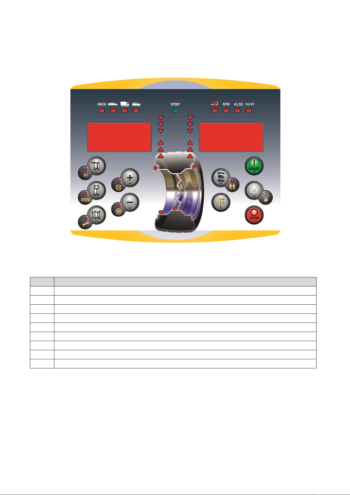
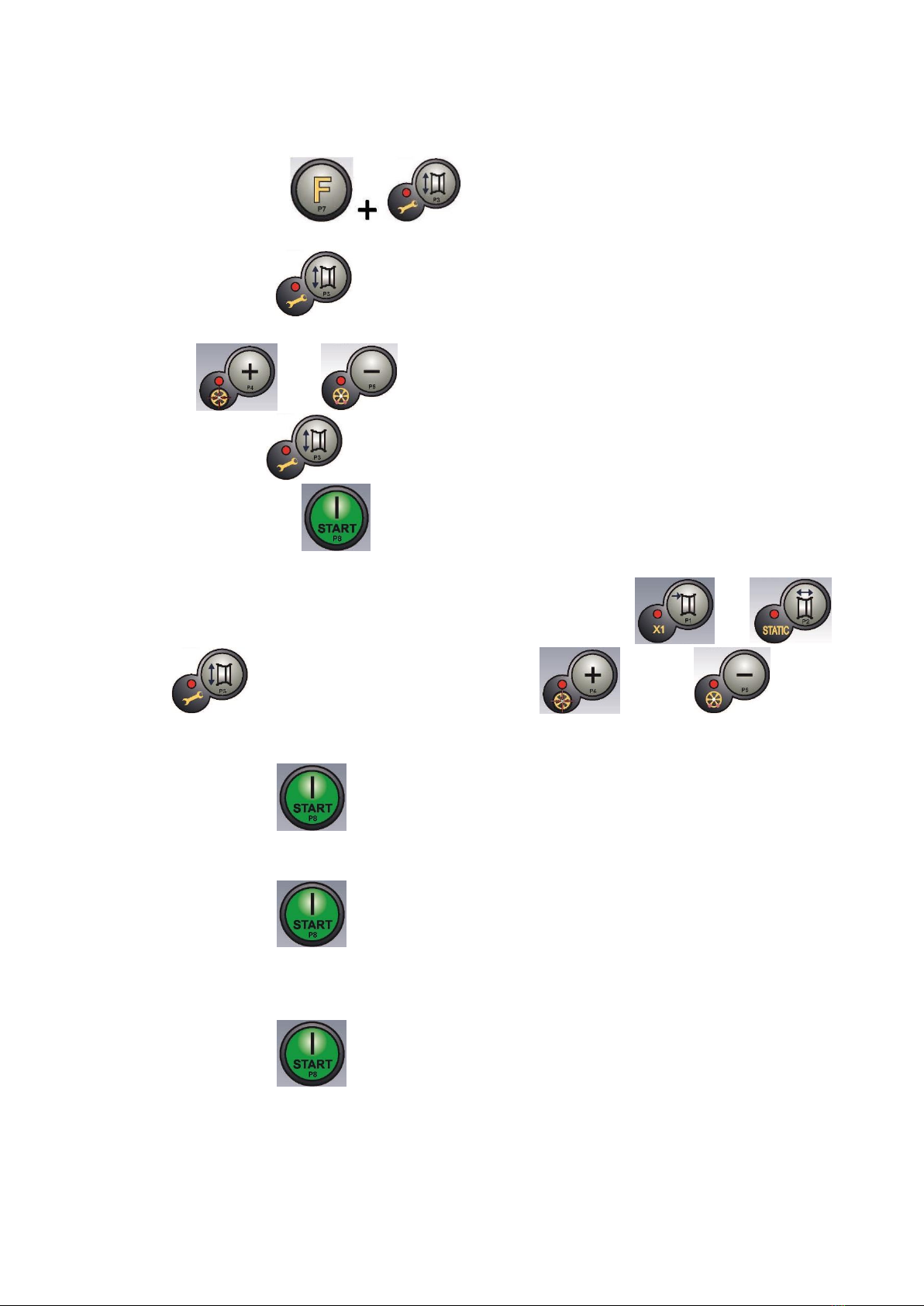
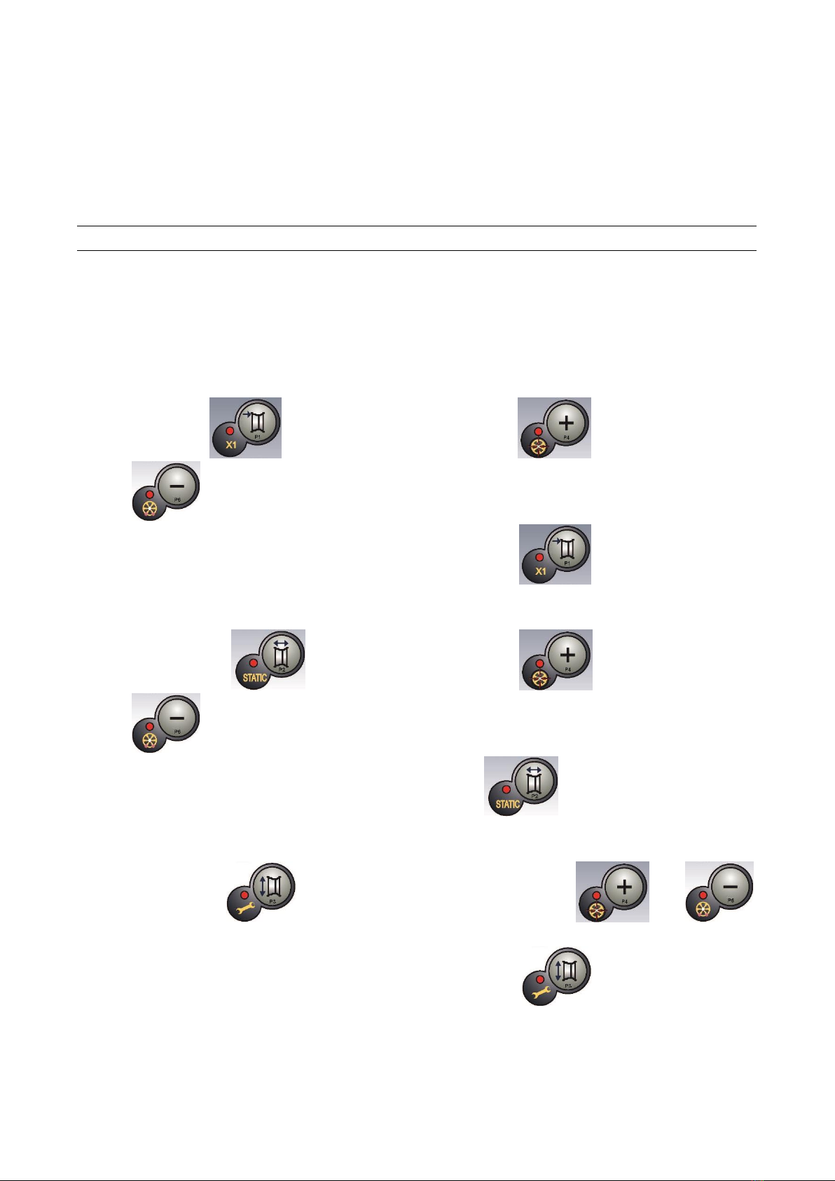
7. Mount the wheel on the shaft and enter the wheel dimensions by pressing the [P1] , [P2] ,
[P3] to select the dimensions for editing, and the [P4] or [P5] keys to edit the
value. If the dimensions of the wheel have been entered before accessing the calibration program, this step can be
skipped. It is not possible to enter the data with the automatic acquisition system;
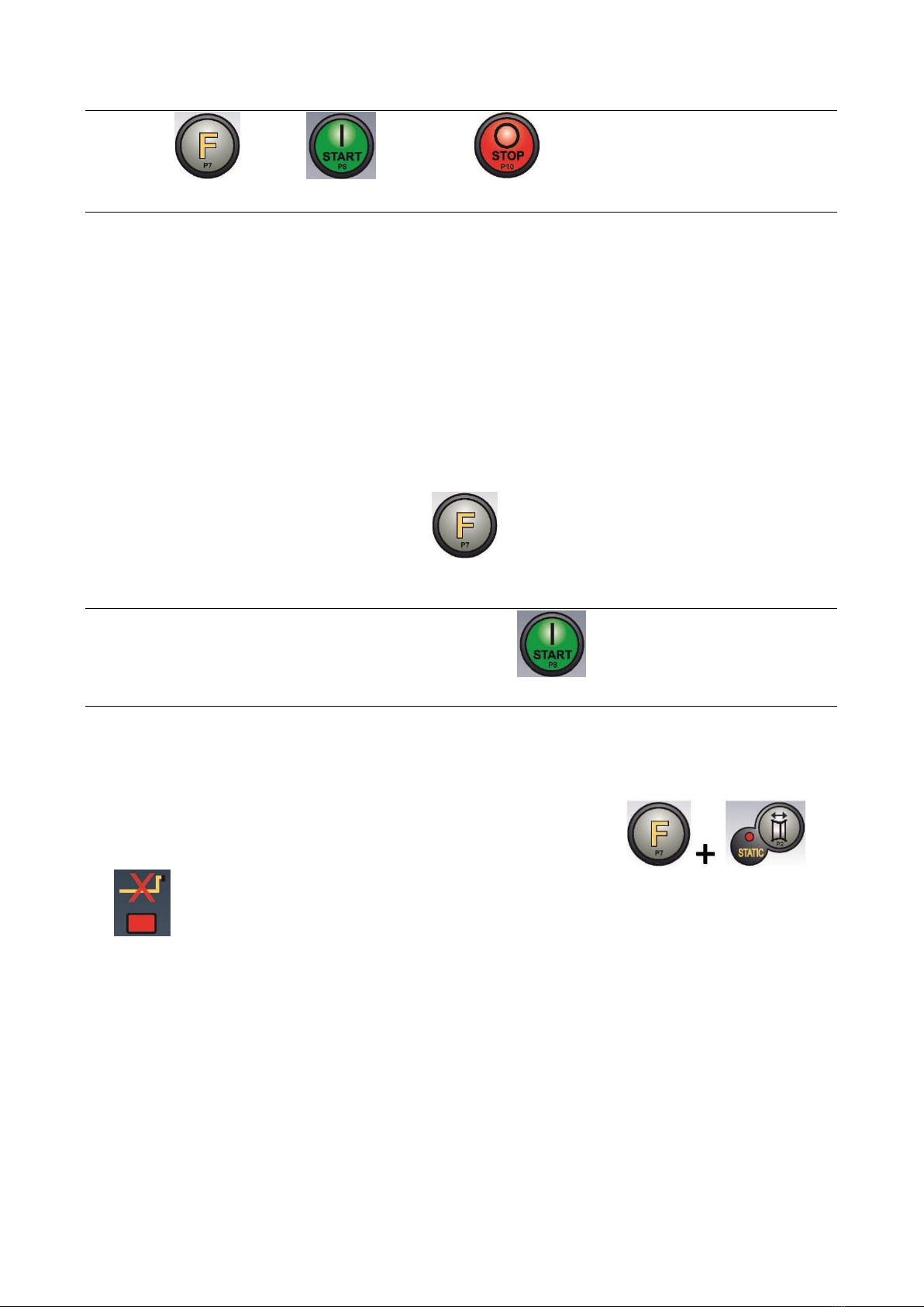
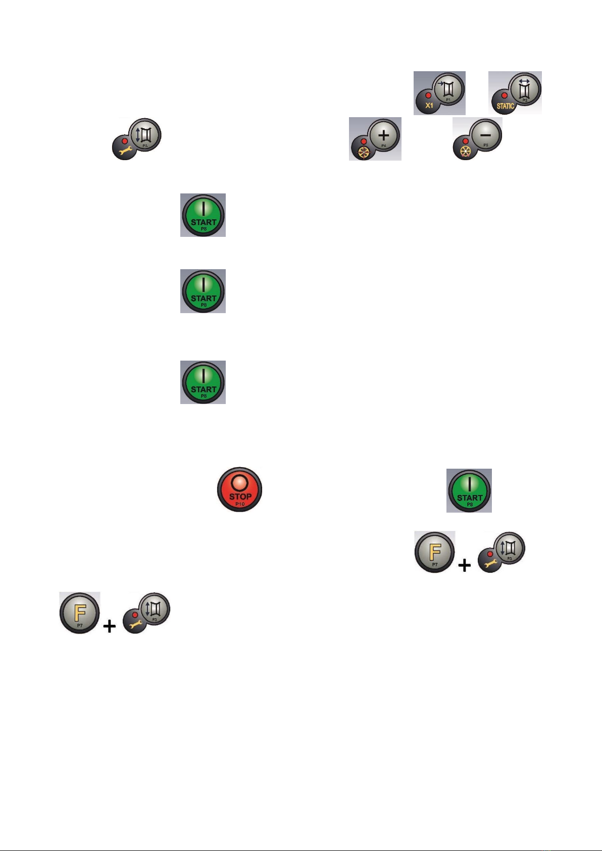
8. Press Start button [P8] : the machine will run a spin cycle;
9. At the end of the spin, manually rotate the wheel until the left display shows the value 300. On the inner side of the
wheel, at 12 o'clock, apply the 300 g weight.
10. Press Start button [P8] : the machine will run a spin cycle;
11. Remove the 300 gr. weight applied on the internal side;
12. At the end of the spin, manually rotate the wheel until the right display shows the value 300. On the outer side of the
wheel, at 12 o'clock, apply the 300 g weight.
13. Press Start button [P8] : the machine will run a spin cycle;
14. Calibration is finished: the machine automatically exits the calibration program and returns to NORMAL mode, ready to
perform balancing.
If you have anomalies during the calibration procedure, the machine will display the error message (for example ERR 025). See
section “21.1 Error codes” and act accordingly to eliminate the problem and continue/repeat/cancel the calibration in progress.
Spins stopped using the [P10] Stop button can be repeated by pressing the [P8] Start button .
How to exit the TRUCK Wheel Type calibration of the machine
At any time it is always possible to exit the calibration procedure in progress by pressing [F+P3] . The
machine will return to SERVICE mode displaying the SER SER writing. To return to NORMAL mode, press [F+P3] again
. The calibration procedure in progress will be cancelled and the machine will use the previous
calibration values.
15.3 Machine calibration for the CAR/SUV Wheel Types
Calibration for the CAR and SUV Wheel Types is the same.
To perform machine calibration, you must first provide for the following material:
A balanced wheel with a steel rim having the following dimensions: Diameter 15” Width 6”. Wheels with dimensions
similar to those specified can also be used provided that the difference is small. It is not possible to use wheels with
aluminium rims.
A 50-gram weight (preferably made of Iron or Zinc).
To perform the machine calibration, proceed as follows:

Use and Maintenance Manual –VER. 2016-02 Page 14
1. Switch on the machine;
2. Remove the wheel and any other accessories from the shaft;
3. Press the [F+P3] button . The words SER SER will appear (this means that we have
entered SERVICE mode (service programs);
4. Press the [P3] button . The words CAL TRC will appear on the screen (machine calibration for truck
wheels);
5. Use [P4] or [P5] to select the type of CAR calibration (auto-vehicle and light off-road wheels).
6. Press the [P3] button . The words CAL 0 will be displayed;
7. Press the [P8] Start button . The machine will perform a set of four short spins followed by a complete spin.
At the end the words CAL 1 will appear on the screen.
8. Mount the wheel on the shaft and enter the wheel dimensions by pressing the [P1] , [P2] ,
[P3] to select the dimensions for editing, and the [P4] or [P5] keys to edit the
value. If the dimensions of the wheel have been entered before accessing the calibration program, this step can be
skipped. It is not possible to enter the data with the automatic acquisition system;
9. Press Start button [P8] : the machine will run a spin cycle;
10. At the end of the spin, manually rotate the wheel until the left display shows the value 50. On the inner side of the wheel,
at 12 o'clock, apply the 50 g weight.
11. Press Start button [P8] : the machine will run a spin cycle;
12. Remove the 50 gr. weight applied on the internal side;
13. At the end of the spin, manually rotate the wheel until the right display shows the value 50. On the outer side of the
wheel, at 12 o'clock, apply the 50 g weight.
14. Press Start button [P8] : the machine will run a spin cycle;
15. Calibration is finished: the machine automatically exits the calibration program and returns to NORMAL mode, ready to
perform balancing.
If you have anomalies during the calibration procedure, the machine will display the error message (for example ERR 025). See
section “21.1 Error codes” and act accordingly to eliminate the problem and continue/repeat/cancel the calibration in progress.

Use and Maintenance Manual –VER. 2016-02 Page 15
Spins stopped using the [P10] Stop button can be repeated by pressing the [P8] Start button .
How to exit machine calibration for the CAR/SUV Wheel Type
At any time it is always possible to exit the calibration procedure in progress by pressing [F+P3] . The
machine will return to SERVICE mode displaying the SER SER writing. To return to NORMAL mode, press [F+P3] again
. The calibration procedure in progress will be cancelled and the machine will use the previous
calibration values.
16. USE OF THE MACHINE IN NORMAL MODE
Display for the machine controls
To use the machine, select or set the following:
Program Type (program for wheels with steel, aluminium or special aluminium rims). Default = program for wheels with
steel rims;
Wheel Type (car, truck, SUV). Default = truck;
Size of the wheel to be balanced. The measurements can be entered manually (always) or in partially automatic mode.
Dynamic or Static Balancing. Default = Dynamic;
Display resolution X1 or X5. Default = X5.
The selections described above can be entered before or after the spin. For any variation of the selections or data settings, the
machine will run a recalculation by displaying the new imbalance value.
When the required selections/settings have been made it is possible to run a spin cycle by pressing [P8] Start . At the
end of the spin, the machine displays the wheel imbalance values.
Apply the weights displayed by the machine in the indicated positions, and then run a second test spin. Normally, weights should
be applied at 12 o’clock, with the exception of special programs for ALS1 and ALS2 aluminium.
16.1 Program Type
The machine allows the choice between eight different Program Type of balancing as listed in table T16.1.
Table T16.1: Program types available

Use and Maintenance Manual –VER. 2016-02 Page 16
Program Type
Wheel
material
Position of weights along the
rim section
Automatic
acquisition
Notes
STD
Steel
Default
1 sensor
Default at power-on
ALS1
Aluminium
Default for inner weight,
provided by user for outer
weight
1 sensor
ALS2
Aluminium
Provided by user
1 sensor
Programs can be selected in NORMAL mode by pressing key [P4] or [P5] . On the first press of one of
these two keys, the Type of Program currently selected is shown on the displays; if, within a lapse of 1.5 seconds, neither of the two
keys is pressed again, the display returns to its previous status without changing the Type of active Program. The following LEDs
will light up on the control panel depending on the Type of active Program:
Program Type LED. See Picture F13.1.
Imbalance Weight Position LED. See Picture F13.1.
Note: Selecting the STD Program Type eliminates the Static Imbalance display selection.
The selected Program Type also affects the automatic acquisition mode of the wheel measurements as stated in the
Automatic Acquisition column of Table T16.1. The position of the balancing weights along the section of the rim in the various
Program Types is shown in figure F16.1.
Picture F16.1: Position of the weights in the various Program Types along the section of the rim
The angular position of the balancing weights in the various Program Types is shown in table T16.2.
Table T16.2: Angular position of balancing weights in various Program Types
Machine data
acquisition
system
Program Type
STD
ALS1
ALS2
Internal
plane
External
plane
Static
Plane
Internal
plane
External
plane
Static
Plane
Internal
plane
External
plane
Static
Plane
Manual
H12
H12
H12
H12
H6
H6
H6
H6
H6
Semi-automatic
H12
H12
H12
H12
Sensor-
rim
contact
point (1)
H6
Sensor-
rim
contact
point (1)
Sensor-
rim
contact
point (1)
H6
Note (1): if the data acquisition system is disabled, the angular position of the weight will be in the 6 o’clock position.
In table T16.2, “H12” indicates that the angular position of the weight is at 12 o’clock while “H6” indicates that the angular position
of the weight is at 6 o’clock.
16.2 Wheel Type
The machine allows choosing between three different Wheel Types as listed in table T16.3.
Table T16.3: Wheel Types to select
Wheel Type
Vehicle
Notes

Use and Maintenance Manual –VER. 2016-02 Page 17
CAR
Cars
TRUCK
Trucks
Default at power-on
SUV
Off-road vehicles
Not suitable for balancing truck wheels
Each of the above programs sets specific values to measure wheel sizes and calculate imbalances. The special features of each
program are listed in the following paragraphs.
To select a specific Wheel Type, press the [P6] key repeatedly until the relative LED lights up, as shown in table T16.3.
16.2.1 CAR wheel type (passenger cars)
Selecting the CAR Wheel Type allows balancing passenger car wheels. For off-road vehicles, it may be appropriate to select the SUV
Wheel Type (see paragraph below).
To select the CAR wheel type, press the [P6] key repeatedly until the CAR LED of the LED Wheel Type group lights up.
See table T16.3.
16.2.2 TRUCK wheel type
Selecting a TRUCK wheel type allows balancing truck wheels.
To select the TRUCK wheel type, press the [P6] key repeatedly until the TRUCK LED of the LED Wheel Type group
lights up. See table T16.3.
16.2.3 SUV wheel type (off-road vehicles)
Selecting the SUV wheel type allows balancing off-road vehicle wheels. These vehicles are generally equipped with wheels that are
larger than normal, and the tyre is relatively large compared to the diameter of the rim (i.e. not the low profile or super low profile
types). The selection for this wheel type does not allow balancing truck wheels, because the latter have rims with considerably
different profiles.
The choice of the CAR or SUV wheel type is at the discretion of the operator who should run balancing tests to determine which
Wheel Type gives the best results for the particular wheel to be balanced.
To select the SUV type wheel, press the [P6] key repeatedly until the SUV LED of the LED Wheel Type group lights up.
See table T16.3. For SUV wheel type all Programs Type listed in table T16.1. are available.

Use and Maintenance Manual –VER. 2016-02 Page 18
The positions of the weights along the section of the rim are the same as those shown in figure F16.1.
16.3 Entering wheel size
The dimensions of the wheel to balance can be entered in two ways:
Manual Mode.
Semi-automatic Mode.
Note: All machines are equipped with a graduated scale for manually measuring distance.
16.3.1 Manual entry of wheel dimensions for the STD and Program Types
To manually enter a wheel size, proceed as follows:
1. Fit the wheel on the shaft and tighten it with the ring nut.
2. Extract the distance sensor and place it on the wheel as shown in Picture F16.2.
3. Read the distance value on the graduated scale as shown in Picture F16.2. The distance value is always expressed in
millimetres.
4. Press [P1] key to change distance and then press the [P4] or [P5] key within 1.5 seconds
to enter the read value. If you do not press the [P4] or [P5] key within this time limit, the machine will
return to the previous display. In this case, you can press the [P1] key again to enter or edit the data.
5. Measure the width of the wheel with the special gauge or read the value of the width indicated on the rim. The value of
the width can be in inches or millimetres according to the selected unit of measurement.
6. Press the [P2] key to change the width and press the [P4] or [P5] key within 1.5 seconds
to enter the read value. If neither of these two buttons is pressed in this time limit, the machine will return
to the previous display. In this case, you can press the [P2] key again to enter or edit the data;
7. Read the value of the diameter indicated on the rim or tyre. The value of the diameter can be in inches or millimetres
according to the selected unit of measurement.
8. Press the [P3] key to change the diameter value and then press the [P4] o [P5]
within 1.5 seconds to enter the read value. If neither of these two buttons is pressed in this time limit, the machine will
return to the previous display. In this case, you can press the [P3] key again to enter or edit the data.
Picture F16.2: Manual acquisition of wheel dimensions: placing the Distance sensor

Use and Maintenance Manual –VER. 2016-02 Page 19
16.3.2 Manual entering of the wheel dimensions for ALS1, ALS2 program types
To manually enter a wheel size, proceed as follows:
1. Fit the wheel on the shaft.
2. If the selected program type is ALS1, extract the distance sensor and place it on the wheel as shown in Picture F16.3,
otherwise proceed with step 4.
3. If the selected program type is ALS2, remove the distance sensor and place it on the wheel as shown in Picture F16.4.
4. Read the internal plane distance value on the graduated scale. The distance value is always expressed in millimetres.
5. Press the [P1] key once to view the parameter di1 (internal plane distance) and, within 1.5 seconds, press
the [P4] or [P5] key to enter the read value. If neither of these two buttons is pressed in this
time limit, the machine will return to the previous display. In this case, you can press the [P1] key again to
enter or edit the data;
6. Remove the distance sensor and place it on the plane selected for the external weight as shown in Picture F16.5.
7. Read the distance value on the graduated scale. The distance value is always expressed in millimetres.
8. Press the [P1] key twice in quick succession until di2 (external plane distance) is viewed and, within about
1.5 seconds, press [P4] or [P5] tp enter the read value. If neither of these two buttons is
pressed in this time limit, the machine will return to the previous display. In this case, you can press [P1]
twice in rapid sequence to enter or edit the data.
9. Press [P3] once to view da1 (internal plane diameter) and within about 1.5 seconds press [P4]
or [P5] to enter the value obtained with one of the two methods specified in the below note.
If neither of these two buttons is pressed in this time limit, the machine will return to the previous display. In this case,
you can press the [P3] key again to enter or edit the data.
Table of contents
Other BRIGHT Wheel Balancer manuals