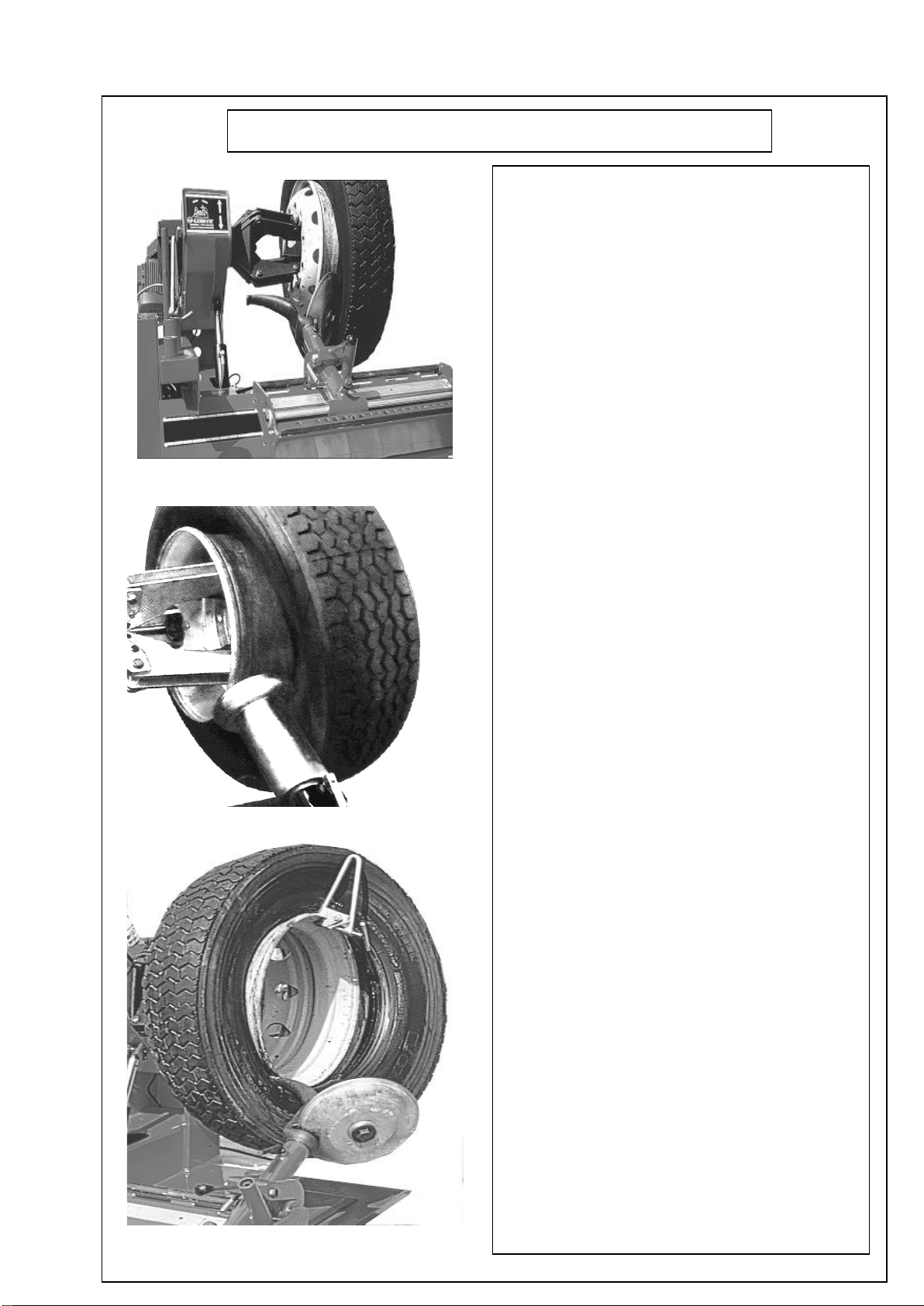
Unitrol AT-26 User manual

INSTRUCTIONS BOOKLET
Automatic Truck Tyre Changer
Machine
AT 14”–26”

2
The machines which are produced by UNI-TROL Co. Ltd. are under warranty against
defects of the material and production for one(1) year from date of it is sold.
Our Company UNI-TROL Co. Ltd. is not responsible for the damages or defects due to
damages occured by faulty used and out of purpose use.
If the defects and damages are occured during the warranty, after making analysis by
technical staff and if the material and production fault is found, the damaged parts will
be replaced with new one.
Warranty covers all parts of the machine during the warranty.
ATTENTION: you have to put thermic switch which is suitable to motor ampere on your
electric wiring to make electric motor under warranty otherwise in case of any defect
the electric motor will not be under warranty.
Make maintanence of the machine periodicly, monthly and yearly. The defects and
damages which are caused by not making maintanence will not be under warranty.
Without notice to the customer reserves the right to make changes in equipment.

3
WARNINGS
-The presents instructions booklet is an integral part of the product. Carefully study the warnings and
instructions contained in it. This information is important for safe use and maintenance.
-Conserve this booklet carefully for further consultation.
AT TYPE 14”-26”
Is a tyre changing machine designed and constructed to be used for mounting and demounting tyres on the
whell rims of trucks and light industrial vehicles.
The machine has been designed to operate within the limits described in this booklet and in accordance
with the maker’s instructions.
The machine must be used only for the functions for which it was expressly designed. Any other use is
considered wrong and therefore unacceptable.
The maker cannot be held responsible for eventual damage casued by improper, erroneous or
unacceptable use.
IMPORTANT
AT may be operated only by suitably trained personnel. Any work on the electrical, hydraulic, pneumatic
systems must be conducted only by profesionally qualified personnel.
10 years in the life of the machine.
CONTENTS
PAGE
1 -General warnings.......................................................................... 2
2 -Technical characteristics............................................................... 2
3 -Parts of the machine...................................................................... 3
4 -Acessory provided, movement, unpacking.................................... 4
5 -Electrical connection..................................................................... 5
6 -Tubeless and supersingle tyres..................................................... 6
7 -Agricultural tyres........................................................................... 7
8 - Problems, causes, remedies........................................................ 8
9 -Demontage plan........................................................................... 10
10 –Spare parts list............................................................................. 11
DIMENSIONS
Height (min./max.)......................................... 700 - 1160 mm
Depth............................................................. 1400 mm
Widht (min./max.).......................................... 1415-1920 mm
WEIGHT
Net weight...................................................... 530 kg
ENGINE DATA
Reduction engine ......................................... 1.5 Kw –1400 rpm
3 phases
Reduction turning speed……..…………........ 5.5 rpm
Hydraulic engine ........................................... 1.5 Kw –1400 rpm
3 phases
Noise level .................................................... 75 dbA
TECHNICAL CHARACTERISTICS
RANGE OF APPLICATIONS
AT can operate on wheels having the following minimum and maximum dimensions:
WHEEL
Work on wheels of............................................. 14” - 26”
Max. Wheel diameter......................................... 1600 mm
Max. Wheel width.............................................. 820 mm
WARNING !
It is absolutely prohibited to carry out tyre inflation procedures while the wheel is still on the machine!
At least two people are required for the movement of particularly heavy wheels!
WHEEL LOCKING SYSTEM
The self-centering chuck operates by means of a high pressure hydraulic circuit adjustable from 20 to
110 bar. The handle is turned and the pressure read on the manometer. Standart working pressure is
110 bar, but for weak or particularly thin rim it is necessary to reduce this pressure.

4
PARTS OF THE MACHINE
Fig.1 –FOUR-JAW UNIVERSAL CHUCK
With two rotation speeds in both directions.
Pressure adjustable hydraulic opening and
closing.
Fig.2 –LOCKING JAWS
The jaws were designed to give different
clamping possibilites.
Fig.3 –CHUCK ARM
CONTROL UNIT
Fig.4 –AT 14” – 26”
Fig.5 –MOBILE CONTROL UNIT
The controls are combined on a remote
mobile control unit with which the
operations are coordinated.
Fig.6 –HYDRAULIC UNIT
By regulating the operating pressure
of the chuck, the unit allows safe
working conditions even on the
various types of alloy rim.
Fig.7 –WORKING ARM
A quick rotation system helps
changes in operation during the
various stages of bead breaking
tool-assisted extration of tyre etc.
56
3
2
1
4

5
Fig. 8
Fig. 9
ACCESSORIES PROVIDED
BEAD LIFTING LEVER ( Fig. 8 )
A toll necessary for lifting the tyre bead onto
the head during demounting.
RIM PINCERS ( Fig. 9 )
These are used when mounting tubeless and
supersingle tyres.
MOVEMENT ( Fig. 10 )
For installation and ulterior movement of the
machine, follow the instructions:
- Herness with cables ( one of 1.5 m. and one
of 2 m. ) at the two points indicated.
- Lift with a hoist of suitable strength.
N.B. : Whenever it is necessary to move the
machine take all precautions to guarentee safe
conditions.
NET WEIGHT : 530 Kg
Fig. 10
UNPACKING ( Fig. 11 )
On receipt of the machine remove the packing
an chack the machine visually for missing or
damaged parts. If in doubt do not use the
machine and refer to professionally qualified
personnel and/or to the seller.
WARNING !
The packing materials must not be left within
reach of children since they are potantially
dangerous.
Deposit the above mentioned materials at the
relevant collection points if they are pollutants
or are non biodegradable.
Fig. 11

6
INSTALLATION
Fix the machine from its connection holes (it is shown figure 12) on the ground by help of steel wall
plug. This function must be done to machine to work safely and longevously. If the connection function
of the machine is not done, it can causes undesirable results such as the tire cutting, rim scratch,
mechanical damages on the machine. Therefore it should not be failed, otherwise because of the
encountered problems it can not be under warranty.
Fig. 12

7
Fig. 13
Fig. 14
ALL WORKS ON THE ELECTRICAL
SYSTEM, INCLUDING MINOR
OPERATIONS,
MUST BE CARRIED OUT BY
PROFESSIONALLY
QUALIFIED PERSONNEL
- Check that the cable mains supply is the same as
that shown on the registration plate.
- Connect the cable to a plug that conforms with
European norms or to the norms of the country in
which the machine is used.
- The plug must have an earth terminal. ( Fig. 13 )
- Check that the earth connection is efective.
- The machine must be connected to the mains
through a multipole isolating switch which
conforms with European norms and with contact
openings of at least 3 mm.
- Check that the multipole connector on the
electrical board is correctly connected.
- When the machine is connected, switch it on and
check the correct direction of rotation. This should
be as shown by the arrow on the motor unit.
( Fig. 14 )
- If the rotation is reversed, reverse the two wires in
the connection plug.
- If the machine behaves abnormally, immediately
switch off the main switch ( Fig. 15 ) and check the
section “Malfunctions causes and possible
remedies“ in the instructions manual.
BEFORE STARTING WORK, LET THE
ENGINE IDLE FOR 10 MINUTES IN THE
AUTUMN AND WINTER MONTHS.
START WORK LATER.
AT THE OIL SYSTEM USE SHELL
TELLUS 46 ONLY OR OTHER
HYDRAULIC OIL VISCOSITY 46.
THE MANUFACTURER DOES NOT
ACCEPT ANY RESPONSIBILITY FOR
THE FAILURE TO OBSERVE THE
ABOVE MENTIONED INSTRUCTIONS.

8
Fig. 15
TUBELESS AND SUPERSINGLE TYRES
Fig. 16
Fig. 17
DEMOUNTING
- Break the bead at the front part of the tyre and
pushing on the bread, lubricate the rim flange and
the bread with suitable grease ( Fig. 16 ). Repeat
the operation on the back.
- If it is a balcony rim ( that is, inclined from 10” to
15” ) continue the bread – breaking operation until
the tyre has come completely out of the rim.
- This operation is easier with the use of the special
tubeless roller ( Fig. 17 ) which is supplied on
reguest.
N.B. The for the demounting of the particularly
hard textile supersingle tyres or tubeless tyres with
a very high rim flange refer to the instructions for
the demounting of agricultural wheels.
N.B. The bead and the rim flange should be well
lubricated.
MOUNTING
- For mounting undemanding tubeless tyres, place
the tyre on the trolley keeping it tilted. Then insert
and lower the rim, pressing on the tyre to allow the
top of the rim to enter the tyre.
- If it is not possible use the special pincers
supplied ( Fig. 18 ) and mount the two beads at the
same time. To mount the second bead proceed as
shown in.
N.B. For mounting particularly hard tubeless and
supersingle tyres, treat them as agricultural
wheels.
Warnings!
It is absolutely forbidden to inflate tyres with
the whell still on the machine.
The movement of particularly heavy whells
requires at least two people.

9
Fig. 18
AGRICULTURAL TYRES
Fig. 19
Fig. 20
DEMOUNTING
- Clamp the whell on the self-centering chuck
and raise it until the rim flange touches the bead
breaking tool. Using the control and selector
deflate the tyre and begin the bead breaking
operation ( Fig. 19 or Fig. 16 ). Use the pedal
and selector to graudally advance the bead
breaking roller turning the spindle continuously.
- Lubricate the bead and the rim flange with the
special lubricant keeping the wheel in movement.
When the operation is finished rotate the tool by
180º, removing the pin. Repeat the bead
breaking on the other side of the tyre in the same
way.
- Tilt the toll arm and move it back of the tyre
pressing the pedal. Using the lever swing the tool
into position 2 then re-attach the tool arm to the
trolley. Use the control to move the tool againts
the tyre with the control until the bead is hooked
on Fig. 20. Put the tyre into tension moving the
rim away from the tool so that the bead enters
the channel.
- Insert the special lever ( Fig.21/Fig. 8 ) between
the rim and bead to the right of the tool to ensure
that the bead remains on the tool. Move the rim
towards the tool again ( Fig. 21 ) until the front
bead has completely come out. Rest the wheel
on the trolley platform to obtain working space for
the easy removal of the inner tube.
- To demount the back bead proceed as shown
in Fig. 12 rotate the tool by 180º, insert it
between the rim and the bead, move it against
the rim flange and insert the lever ( Fig 20 ) and
then rotate the spindle in clockwise direction until
the operation is complete.
MOUNTING
- Place the tyre on the rim, clamp the special
pincers( Fig. 18/Fig. 9 ) on the front rim flange
and position the tool with reference to the edge
of the rim flange.
- Rotate the spindle in a clockwise direction until
the back rear bead is fully mounted.
- İnsert the inner tube and support the wheel on
the trolley platform ( Fig. 18 ) to assist the
operation.
- Re-position the tool near to the valve with the
relevant referance point on the edge of the rim.
Clamp the pincers ( Fig.18/Fig. 9 ) to the left of
the tool and rotate the wheel clockwise making
sure that the bead is inside the rim channel.
Fig. 21

10
PROBLEMS
CAUSES
REMEDIES
- If you have problems while thegear
box head is going up and down.
- If you have problems during the
locking head movements.
- If you have problems during the
movements of tyre changer table.
- The pressure valve may be blocked.
( Figure 1 / Valve 1 )
- The pressure valve may be blocked.
( Figure 1 / Valve2 )
- The pressure valve may be blocked.
( Figure 1 / Valve 3 )
- Open the valve cover and by using pim
of max 5 mm diameter unblock the
valve.( Figure 1 )
- The engine is working but the locking
head is not turning.
- The engine belt may be untightened.
- Check the engine belt.
- There is not enough pressure in the
hydraulic unit
- The direction of the hydraulic unit may be
reverse.
- There may be lack of oil in the hydraulic unit.
- Change the cables vice in the
connection.
- Put oil till the level of the insdicator.
- The locking head is not working.
- The o-rings of the locking valve may be
damaged.
- The enter o-ring may be damaged.
- Change the o-rings.
- Call our technical service.
- The locking head is not turnig to the
right or left
- The gear box body is not moving up
and down.
- Tyre carriying table is not moving.
- There may be a problem with the electrical
connections.
- Call our technical service.
Figure : 1
1 –Gearbox Up Down Valve
2 –The Locking Head Valve
3 –Changer Table Valve
WARNING !!
Do not press on the cable of the remote
control system may fall,
cable ıs protected by spıral and sprıng
ıncase of droppıng and smashıng parts
WARNING!
Do not step on the cable of the remote
control system. Cable ıs protected by
spıral and sprıng ıncase of droppıng
and smashıng parts.
Before operating the machine,
lubricate the area shown in the
figure.

11
When the machıne is workıng or the machıne stopped, anybody except
the operator doesn’t apporoach to the machıne and the each sıdes of
the machıne must be empty at least 1,5 m.
OILING PERIODS
1.5 M
1.5 M
1.5 M
1.5 M
* HEAD LIFT CYLINDERS AND MOTOR MONTHLY LUBRICATED.
CLEANED ON A WEEKLY BASIS
AFTER THE THIN WITH GREASE LUBRICATED.
DETACHABLE CLEANING WEEKLY IN ARM
AFTER THE THIN WITH GREASE LUBRICATED.
WORM GEAR MONTHLY LUBRICATED.
MONTHLY LUBRICATED.
WEEKLY LUBRICATED.

12
ROUTINE MAINTENANCE
DAILY
1) CHECK THE CABLE OF THE MACHINE BEFORE THE RUNNING.
2) CHECK THE MACHINE IF THE MACHINE IS CLEAN AND MAINTENANCE IS COMPLETED.
3) CHECK THE HYDRAULIC CYLINDER AGAINST THE AIR LEAKAGE.
WEEKLY
1) CHECK IF THE DAILY MAINTENANCE IS DONE SYSTEMATICALLY.
2) CHECK IF THERE IS ANY OIL LEAKAGE ON THE CYLINDEROF THE BEAD LIFTING.
3) CHECK IF THERE IS ANY PROBLEM ON THE SWITCHES AND CONNECTION OF THE MACHINE.
MONTHLY
1) CHECK IF THE DAILY AND WEEKLY MAINTENANCES ARE DONE.
2) CHECK THE MACHINE PEDALS.
3) CHECK THE BELT OF THE MOTOR.
4) CHECK THE CONNECTION OF THE GEARBOX.
5) CHECK THE MOTOR CONNECTION BOLTS.
6 MONTHLY
1) CHECK THE DAILY, WEEKLY AND MONTHLY MAINTENANCE ARE DONE.
2) CHECK IF THERE IS ANY CONNECTION PROBLEMS ON THE CABLES AND SOCKET.
3) CHECK THE EARTH CONNECTION OF THE MACHINE ELECTRIC SYSTEM.
4) CHECK THE ADJUSTMENT OF THE DISMANTLING AND FIXING ARM.
YEARLY
1) CHECK THE DAILY, WEEKLY, MONTHLY AND 6 MONTHLY MAINTENANCE ARE DONE.
2) ARE THERE ANY UBNORMAL NOISES COMING FROM THE MACHINE.
3) ARE THERE ANY UBNORMAL NOISES COMING FROM THE ENGINE.
4) ARE THERE ANY UBNORMAL NOISES FROM THE MACHINE WHEN THE MACHINE IS NOT WORKING BUT
PLUGGED.
5) IS THERE ANY HEATING IN THE CABLES.
6) IS THERE ANY UBNORMALITYIN THE ENGINE DURING THE OPERATION.
IF ANY ANSWERS OF THESE GUESTIONS ARE YES CALL THE TECHNICAL SERVICE IMMEDIATELEY DO NOT
TRY TO SOLVE THE PROBLEMS BY YOURSELF.

13
MACHINES HAVE 1 YEARS GUARANTEED.
PLEASE CONTACT WITH YOUR DEALER FOR THE PROBLEMS AND WHEN YOU NEED A SERVICE.
***OUR GUARANTEE DOESN’T CONTAIN ELECTRIC MOTOR
FOR SPARE PARTS ORDER:
PLEASE INFORM THE SERIAL NUMBER OF THE MACHINE AND MANUFACTURING YEAR.
PLEASE INFORM THE PART CODE.
PLEASE INFORM THE QUANTITIES.
GUARANTEE
ATTENTION
PLEASE DON’T TRY TO REPAIR IF THE PERSONAL IS NOT OUR REGISTERED SERVICE MAN.
CONTROL BUTON CIRCUIT PLAN ( 3 PHASES )
Mirror Open
Up
CONTROL ARM
Down
MOVEMENT MOTOR
3A 3A
Left
EMERGENCY STOP
Right
HYDRAULIC MOTOR
MP
MP

14
DEMONTAGE PLAN

15

16

17
SPARE PARTS LIST FOR AT TYPE
ITEM NO
ITEM/CODE NUMBER
DESCRIPTION
1
66 01 000
BOTTOM BODY GROUP
2
01 0134 02
CUFFS OF CABLE 20
3
01 0072 025
IMBUS BOLT SCREW M6X20
4
53 03 000
SLEDGE CYLINDER GROUP
5
53 03 001
SLEDGE PISTON CYLINDER
6
53 03 002
PISTON GROUP
7
53 03 003
TİREHEAD
8
53 03 004
NUT OF PISTON
9
53 03 005
SLEDGE CONNECTION SPINDLE
10
53 03 006
BODY CONNECTION SPINDLE
11
01 0139 025
SPINDLE PISTON RING Ø 25
12
01 0116 22
NUT SCREW M22X1,5
13
01 0022 060-044
COMPACT SET
14
01 0024 017-2,5
O-RING Ø17X2,5
15
01 0024 055-3
O-RİNG Ø5X3
16
01 0021 35-46,3-10
NUT-RING 46,3X35X10
17
01 0024 035-3
O-RING Ø35X3
18
01 0024 059-3
O-RİNG Ø59X3
19
01 0023 35
DUST RUG 35-43-7
20
01 0136 006
GREASE NİPPLE
21
01 0064 025
BOLT SCREW M12X25
22
53 01 013
SPINDLE CONNECTION WASHER
23
53 01 012
TOP BEARING SPINDLE
24
66 02 004
PISTON TOP PLATE
25
01 0072 016
IMBUS BOLT SCREW M6X16
26
01 0112 06
WASHER M6
27
53 02 003
CARRIER SLEDGE HIVE
28
53 02 002
CARRIER EAR HIVE
29
01 0139 045
SPINDLE PISTON RING Ø45
30
53 02 005
BOTTOM BEARING SPINDLE
31
53 02 006
SUPPORT SPINDLE
32
53 05 007
LOCKING SPINDLE
33
01 0031 43
PRESSURE SPRING
34
53 05 005
SLIDING STITCHER
35
01 0139 020
SPINDLE PISTON RING Ø20
36
01 0112 08
WASHER M8
37
01 0073 016
IMBUS BOLT SCREW M8X16
38
53 05 002
PRESSURE PISTON
39
01 0031 01
PRESSURE SPRİNG OF CHANGİNG ARM PART
40
53 05 006
SPRİNG WASHER
41
01 0140 034
HOLE PİSTON RİNG Ø34
42
01 0031 02
PULLING SPRING
43
01 0117 016
FİBER NUT M16
44
53 05 004
HOOK GROUB
45
01 0112 16
WASHER M16
46
01 0065 140
BOLT SCREW M16X140
47
66 05 000
TIRE CARRIAGE GROUP
48
33 21 002
RAMP WHEEL
49
01 0117 008
FİBER NUT M8
50
01 0075 090
IMBUS BOLT SCREW M12x90
51
53 07 000
LIFTIN HEAD PISTON GROUP
52
53 07 001
CYLINDER GROUP
53
53 07 002
PISTON GROUP
54
66 04 000
BODY GROUP OF GEAR-BOX
55
53 15 000
SUPPORTING SPINDLE GROUP
56
01 0072 035
IMBUS BOLT SCREW M10X35
57
01 0149 25
ASPİRATED FİLTER 25 (METAL)
58
53 08 005
PUMP EXIT PIPE
59
01 0014 20
RECOR 3/8-10 NB/R
60
53 08 006
STORAGE RETURN PIPE
61
01 0131 1-2
½ COPPER WASHER
62
01 0034 03
TANK TOP SCREW
63
53 08 001
TOP COVER GROUP
64
01 0155 01
COVER OF TANK WITH SMALL SCREW
65
01 0060 016
BOLT SCREW M5X16
66
01 0147 01
BRAKE DRUM 1K 200
67
01 0034 01
ENGINE SCREW
68
01 0273 09-B-5
ENGINE
69
01 0112 10
WASHER M10
70
01 0074 035
IMBUS BOLT SCREW M10X35
71
01 0135 1-4
BLIND BUNG
72
53 08 002
OIL TANK GROUP
73
01 0137 1-2 AL
LEVEL INDICATOR ½ ALUMINUM
74
53 08 004
FİLTER TRANSİTİON RECORD
75
53 08 003
PUMP FILTER CONNECTION PIPE

18
SPARE PARTS LIST FOR AT TYPE
ITEM NO
ITEM / CODE NUMBER
DESCRIPTION
76
01 0014 21
ROTATING OUTRIGER RECORD 3/8 10NB/R
77
01 0145 09
CAPRONI PUMP 20C 4,5-080
78
53 08 007
KAPLIN GROUP
79
01 810123 10
SET SCREW M8x10
80
53 09 001
BODY GROUP
81
01 0024 014-3
O-RİNG Ø14x3
82
01 0014 112
¼ - ¼ RECORD
83
01 0024 009-2
O-RİNG Ø9x2
84
53 09 005
BOTTOM TRANSITION
85
53 09 006
PRESSURE ADJUSTMENT SPINDLE
86
01 0031 04
PRESSURE ADJUSTMENT SPRING
87
53 09 004
SPRING BOTTOM HAD
88
53 09 003
SPRING TOP HAD
89
53 09 002
PRESSURE ADJUSTMENT SCREW
90
01 0115 010
NUT M10
91
01 0124 030
SET SCREW
92
01 0115 010-KS
NUT
93
01 0133 01
MF INJECTOR WASHER Ø9,8Xø19,9X1,8
94
01 0156 02
SELENOID VALVE WINMAN DFA-02-3C60-DC24-35 AM ¼
95
53 16 000
ACCESSORY AND PANEL CONNECTION
96
01 0038 03
ELECTRICITY PANEL
97
01 0200 06
PAKO CIRCUIT SWITCH T203/01-KG10B/E
98
01 0198 21
PLASTIC CABLE RECORD PG20
99
01 0198 16
PALSTIC CABLE RECORD PG16
100
01 0038 03C
PANO INNER PLATE
101
01 0028 42
CABLE WAY 25x40
102
01 0028 64
CONDUCTOR RAIL
103
01 0202 03
TRANSFORMER 380V.24V.100W
104
01 0196 10
CONDUCTOR CL00A301TD
105
01 0028 29
CONNECTOR UK-5N
106
01 0028 28
EARTHED CONNECTOR USLKG5
107
01 0028 26
CONNECTOR STOPPER EW-35
108
53 11 001
COMMAND SETUP
109
01 0115 005
NUT M5
110
01 0060 016
BOLT SCREW M5x16
111
01 0117 006
FİBERLI NUT M6
112
01 0117 008
FİBERLI NUT M8
113
53 11 002C
PEDAL PLATE
114
53 11 002B
CENTERING HIVE
115
01 0073 040
IMBUS BOLT SCREW M8x40
116
01 0071 016
IMBUS BOLT SCREW M5x16
117
01 0072 040
IMBUS BOLT SCREW M6x40
118
53 11 002A
FRONT COVER
119
01 0031 12
PEDAL SPRING
120
53 11 002D
DISTANCE HIVE
121
01 0110 003
BOLT WITH STAR HEAD M3x20
122
01 0028 106
SWITCH MICRO WITH LONG ARM
123
11 12 010A
PLASTIC PEDAL
124
01 0122 006
SET SCREW M6x6
125
01 0048 01
HAND HANDLE
126
01 0107 040
BOLT WITH STARHEAD M4,2x13
127
53 11 003A
PANEL PLATE
128
01 0030 21
BUTON AEG BFPRN
129
01 0030 41
FOUR-WAY-STICK SWITCH
130
01 0030 24
TLM BUTON XB4 BD53
131
53 06 000
MIRROR GROUP
132
53 06 000-K
MIRROR GROUP FRONT SIDE
133
01 0118 1-14
NUT 1”X14 GRINDER
134
53 06 013
CROSS
135
01 0063 050-10.9
BOLT SCREW M10x50
136
53 06 017
FIXING PIN (BOLT)
137
53 06 003
BODY OF MIRROR
138
01 0023 40
DUST RUG40x48x7/5
139
01 0024 040-3
O-RİNG Ø40x3
140
01 0021 040
NUTRİNG 40x50x10
141
53 06 001
CYLINDER GROUP
142
01 0024 005-2,5
O-RİNG Ø5x2,5
143
53 06 006
MAIN SPINDLE
144
53 06 007
SET SCREW
145
53 06 002
FLANGE SPINDLE CLEAT
146
53 06 005
HANDCUFFS/CLAMP
147
53 06 004
TIRE HEAD
148
01 0022 100-075
COMPACT SET100x75
149
01 0024 090-5
O-RİNG Ø90x5
150
53 06 021
CYLINDER COVER
151
01 0139 028
SPINDLE SEGMENT (RING) Ø28
152
01 0150 315-ALT
MANOMETER WITH WITH GLYCERN 63x315

19
SPARE PARTS LIST FOR AT TYPE
ITEM NO
ITEM / CODE NUMBER
DESCRIPTION
153
01 0159 01
LOCKING VALVE
154
01 0159 02C
BLIND STOPPER(BUNG) 1/4
155
01 0159 02D
LOCKING MIDDLE SLIDING SPINDLE
156
01 0159 02E
BLIND STOPPER (BUNG) 7/8
157
01 0063 070
BOLT SCREW M10x70
158
01 0039 03
CLOCK COVER
159
53 04 004
OPPOSITE GRINDER GROUP
160
53 04 009
CLEAT HOLDER REAR LAMA
161
53 04 007
RAYNEL WASHER Ø131xø157x0,5
162
53 04 006
OPPOSITE GRINDER SUPPORT HIVE
163
53 04 010
CLEAT HOLDER FRONT LAMA
164
01 0073 035
IMBUS BOLT SCREW M8x35
165
53 04 004A
OPPOSITE GRINDER FİRST OPERATION
166
53 04 004B
GEAR BOX GRINDER CENTER
167
01 0135 1-2P
BLIND STOPPER ½ PLASTIC
168
53 04 011
PULLEY PLASTIC CONNECTION PLATE
169
01 0072 010
IMBUS BOLT SCREW M6x10
170
53 04 002
INFINITE SPINDLE WITH SCREW
171
53 04 008
INFINITE GRINDER BEARING CENTERING PIN
172
01 0075 020
IMBUS BOLT SCREW M12x20
173
53 04 003
SOLE CONNECTION LAMA
174
01 0053 30205-FAG
BEARING FAG 30205
175
53 04 005
BEARING COVER
176
01 0073 025
IMBUS BOLT SCREW M8x25
177
01 0039 04
GEAR BOX COVER
178
53 04 012
GREASE FITTING CONNECTION PIPE
179
01 0136 005
GREASE FITTING M6 x 90°
180
01 0112 006
WASHER M6
181
01 0012 1025
V-BELT - 9,5x1025
182
01 0042 190-3
ENGINE PULLEY
183
01 0039 02
PULLEY TOP COVER
184
01 0110 002
BOLT WITH STARHEAD M2,5x12
185
01 0039 01
PULLEY BOTTOM COVER
186
01 0065 080
BOLT SCREW M14x80
187
01 0130 014-020-1
RAYNEL WASHER Ø20xØ14x1
188
53 06 012
PULING LAMA
189
53 06 014
PULLING LAMA CONNECTION PIN
190
01 0117 014
NUT WITH FIBER M14
191
53 06 010
CLAMP COUPLING RIGHT LAMA
192
01 0139 014
SPINDLE SEGMENT Ø14
193
53 06 016
CLAMPING ARM
194
53 06 018
ALUMINIUM RIM CLAMPING SCREWS
195
01 0074 045
IMBUS BOLT SCREW M10x45
196
53 06 019
SHORT RIM CLAMPING SCREWS
197
53 06 020
LONG RIM CLAMPING SCREWS
198
53 06 015
CLAMPING ARM CONNECTION PIM
199
01 0111 010
SERRATED WASHER M10
200
53 06 008
CLAMPING LAMA CONNECTION PIN
201
01 0063 050
BOLT SCREW M10x50
202
53 00 004
LEVER
203
53 18 000
GROUP TO PRESS
204
53 18 003
CLAMPING ARM GROUP
205
53 18 004
CLAMPING ARM SLOT HIVE
206
53 18 001
BODY PRESS
207
53 18 002
PRESS SCREW BODY GROUP
208
01 0141 06-030
PIN WITH BREACH M6x30
209
01 0031 14
MULTI BRAKE LINING SPRING
210
01 0117 010
NUT WITH FIBER M10
211
53 13 000
FLANGE CONNECTION PIN
212
33 17 004
CENTERING SPINDLE
213
33 17 002
BODY FLANGE
214
01 0130 040-050-0,5
RAYNEL WASHER PUL Ø40xØ50x0,5
215
53 14 001
BODY WELD GROUP
216
33 17 006
SPRING CONNECTION PLATE
217
53 14 002
CHANGING SCREW
218
01 0031 52
CHANGING SCREW PULLING SPRING
219
33 17 005
CONNECTION SPINDLE
220
53 05 000
TO PULL ATTACHING GROUP
221
33 17 007
SET DISTANCE SCREW
222
01 0115 014
NUT
223
01 0028 30
EARTHED CONNECTOR
224
01 0112 12
M12 WASHER
225
01 0063 25
BOLT SCREW M10x25
226
01 0117 012
FİBER NUT M12
227
01 0112 08,5
WASHER M8
228
66 02 000
SLİDE GROUP

20
UNI -TROL ®UNI - TROL Co. Ltd.
MANUFACTURING PLANT & STORE ul . Estrady 56 , 01 - 932 Warsaw , Poland
tel.(+4822) 8179422 or 8349013 or 8349014 int.
117
http://www.unitrol.com.pl.fax(+4822) 8179422 or 8349013 or 8349014 int.
115 e-mail: off[email protected].pl ; office@unitrol.pl
WHEEL BALANCING MACHINES RIM STRAIGHTENING MACHINES TYRE CHANGERS EQUIPMENT FOR
TYRESHOPS
Statistic no. : 008132994 EC VAT no. : PL5270205246 Register no. : KRS 0000111731 EORI no. :
PL527020524600000
Account : for EURO : BZ WBK SA no. PL 62 1090 1014 0000 0000 0303 1619 (swift code: WBK PPL
PP XXX)
for USD : BZ WBK SA no. PL 49 1090 1014 0000 0001 1720 1435
CE Conformity Declaration
in accordance with directives : 2006/42/EC, 2006/95/EC, 2004/108/EC
We : Uni-trol Co. Ltd.
Ul. Estrady 56
01-932 Warsaw
Poland
declare, under our exclusive responsibility, that the product
Truck tyre changer
Electromechanical, pneumatic and hydraulic device
model AT-26
Serial number..............................................,
concerned by this declaration, complies with all relevant requirements of the Machinery Directive:
- Directive 2006/42/EC (safety machines),
applicable in the essential requirements and relevant conformity assessment procedures, as well as on
the essential requirements of the following directives:
- Directive 2006/95/EC (the low voltage );
- Directive 2004/108/EC (the electromagnetic compatibility).
In order to verification of compliance with the applicable legal regulations have been consulted
harmonized standards and other normative documents:
PN-EN ISO 12100:2012P
Safety of machinery -- General principles for design –Risk assessment and risk reduction
PN-EN 61000-6-3:2008P
Electromagnetic compatibility (EMC) -- Part 6-3: General standards -- Emission standard for environments: residential,
commercial and light industrial
PN-EN 61000-6-4:2008P
Electromagnetic compatibility (EMC) -- Part 6-4: General standards -- Emission standard for industrial environments
PN-EN ISO 13857:2010P
Safety of machinery - Safety distances to prevent hazard zones being reached by upper and lower limbs
Table of contents
Other Unitrol Wheel Balancer manuals