GB
Page 2 of 52
INSTRUCTION, USE AND
MAINTENANCE MANUAL
SUMMARY
SYMBOLS USED IN THE MANUAL ________ 5
1.0 GENERAL INTRODUCTION __________ 8
1.1 Introduction ____________________________ 8
2.0 INTENDED USE _____________________ 8
2.1 Training of personnel __________________ 8
3.0 SAFETY DEVICES ___________________ 9
3.1 Residual risks __________________________ 9
4.0 GENERAL SAFETY RULES __________ 9
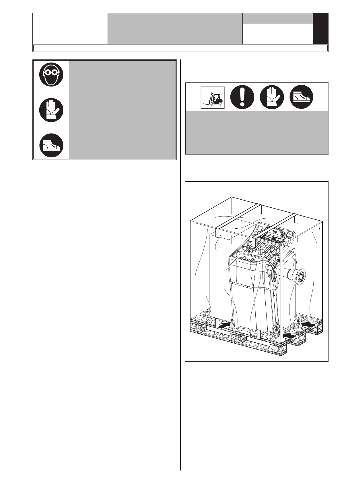
5.0 PACKING AND MOBILIZATION FOR
TRANSPORT _______________________ 10
6.0 UNPACKING ________________________ 11
7.0 MOBILIZATION_____________________ 11
8.0 WORKING ENVIRONMENT CONDI-
TIONS ______________________________ 11
8.1 Working area __________________________12
8.2 Lighting _______________________________12
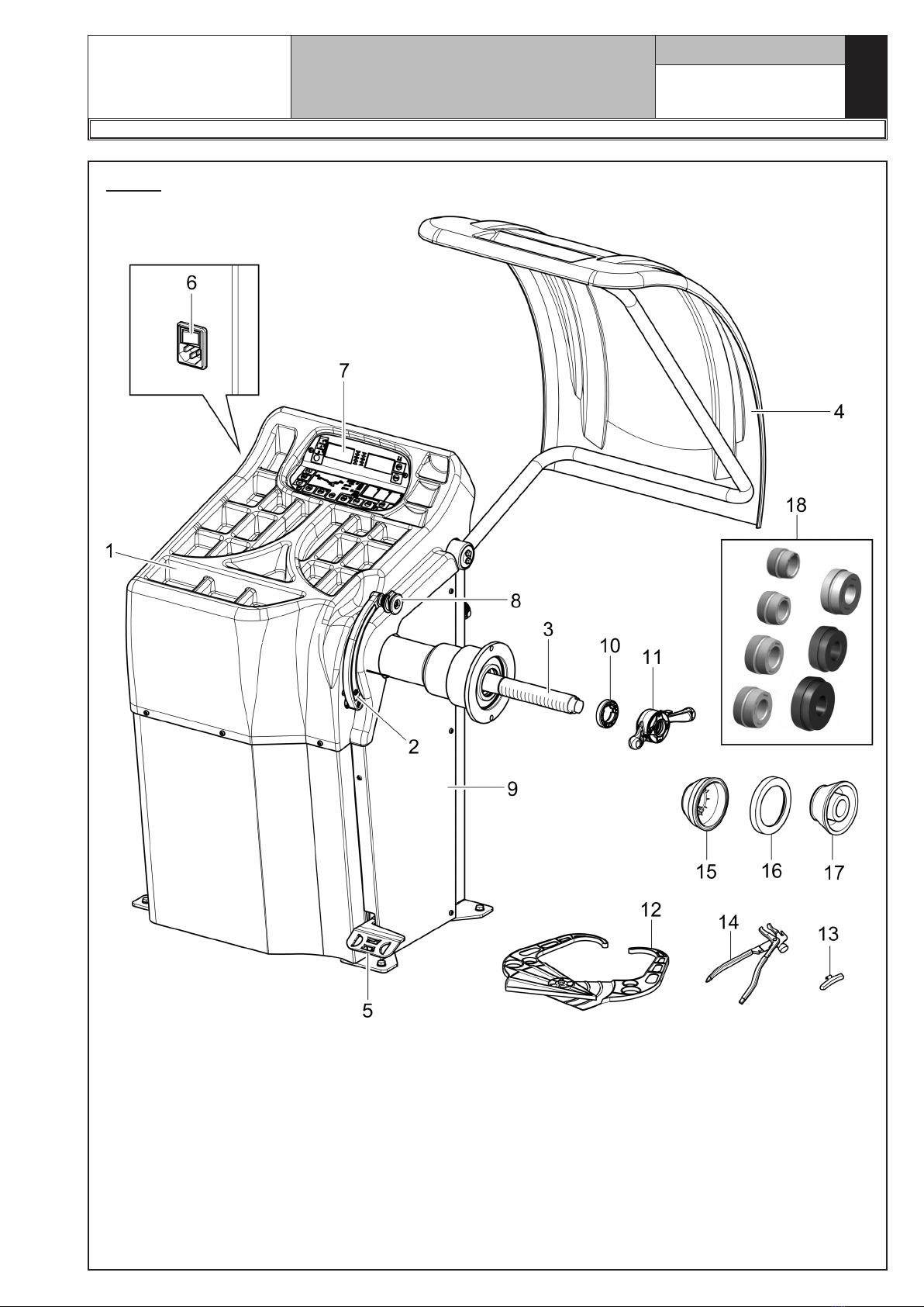
9.0 MACHINE ASSEMBLY ______________ 12
9.1 Anchoring system _____________________12
9.2 Fixtures contained in the packing_____13
9.3 Assembly procedures _________________13
9.3.1 Fitting the mandrel on the flange __13
9.3.2 Fitting the protection guard _______14
10.0 ELECTRICAL CONNECTIONS_______ 14
10.1 Electrical checks ______________________15
11.0 MULTIFUNCTION LED PANEL ______ 15
11.1 DISPLAY and LEDs brightness adjust-
ment___________________________________16
12.0 FITTING THE WHEEL ON THE
MANDREL__________________________ 16
12.1 Wheel assembly _______________________16
13.0 SWITCHING THE MACHINE ON
AND OFF ___________________________ 18
14.0 WHEEL BALANCING _______________ 19
14.1 Determination of wheel dimensions ___19
14.1.1 Automatic wheel dimension set-
ting of distance/diameter __________19
14.1.2 Programs rapid setting and
measurements through distance-
diameter caliper arm ______________21
14.1.3 Entry of measures _________________21
14.1.4 Manual setting of wheel
dimensions ________________________23
14.2 User control function__________________23
14.3 Unbalance measurement ______________24
14.3.1 Indicative display of points where
to fit weight________________________24
14.3.2 Balancing mode____________________24
14.3.3 Dynamic balancing ________________25
14.3.4 ALU-S procedure ___________________26
14.3.5 Static balancing (STAT) ___________26
14.3.6 Positioning the correction
weights on the wheel_______________27
14.4 Measuring the unbalance with auxil-
iary programs ________________________28
14.4.1 ALU1 procedure ____________________29
14.4.2 PAX mode __________________________30
14.5 Recalculation Function ________________30
14.6 ECO-WEIGHT procedure _______________31
15.0 WHEEL BALANCING IN MOTORCY-
CLE MODE _________________________ 32
16.0 SPLIT PROCEDURE ________________ 33
17.0 WEIGHTS HIDDEN BEHIND
SPOKES MODE_____________________ 34
18.0 MATCHING PROCEDURE
(Rim - Tyre Optimization)___________ 36
19.0 CALIBRATION ______________________ 38
19.1 Diameter only gauge calibration ______38
19.2 “Zero mandrel” setting________________40
19.3 Weight measurement sensors
calibration ____________________________40
20.0 USER’S SETTING AND CUSTOMIZA-
TIONS ______________________________ 42
20.1 Selection of unit of measurement for
weights display _______________________43
20.2 Setting measurements units for rim
weight and width/diameter ____________44
20.3 Users’ management - Motorbike mode
- Eco-Weight - Residual static setting__44
20.4 Setting of Repositioning - Comfort -
Guard - Pax____________________________44
20.5 Distance/diameter setting _____________45
20.6 Weights display management _________46
20.7 Setting adhesive weight dimensions __46
21.0 ERROR SIGNALS ___________________ 47
1297-M043-0