Bollhoff RIVNUT B 4090 User manual

R I V N U T ®B4090
The RIVNUT®Battery tool
B4090 05/16 ENG
Visa, Mastercard, Discover & AMEX Accepted Fax: 262.252.5033
ISO 9001 CERTIFIED
800.236.3200 - sales@rivet-nut.com
Call Cardinal Components to Order or for a Quote

2
2
Advantages :
3 kN to 22 kN (M3-M10 steel)
24 R IVNUT®/ min
Up to 800 cycles with 1 battery
Internal qualification done with 1 000 000 cycles
BÖLLHOFF quality
RIVNUT®nut & stud compatible
Li-Ion technology battery
R I V N U T ®B4090 – Battery tool
S tandard B ÖL LHOFF ergonomic
•S ingle press trigger function to complete
the entire cycle
•Comfortable & ergonomic handling
E lectro-hydraulic technology
•Well balanced
•Power & reliability in a reasonable weight
S oft coverings for comfortable handling
and for tool protection
L C D s c reen
•Load adjustment
•S etting parameters menu
•Battery level information
•Unscrewing button
New quick tooling replacement
•No tool needed
•Uses the existing mandrel & anvil
Visa, Mastercard, Discover & AMEX Accepted Fax: 262.252.5033
ISO 9001 CERTIFIED
800.236.3200 - sales@rivet-nut.com
Call Cardinal Components to Order or for a Quote

B4090
Total weight
2,12 0,07 0,30 2,49 kg
4 090
3
B uilt for intens ive us e
Optimized ergonomic des ign
Electro-hydraulic technology: the choice for ultimate
peformance with the best reliability whilst maintaining
a reasonable weight
Produces 600 to 800 cycles per battery
1 000 000 cycles qualification – BÖLLHOFF quality
Well balanced tool
S mart lighting to s ee in dark conditions
Precise force adjustment, easy to do from the
screen (possibility to lock it in the menu)
Full menu to personalize your tool to your wish
R I V N U T ®B4090 – C ordless battery tool for R IVNUT®nut & studs
Tool Tooling B attery
+ +
+ +
Total weight
2,20 0,07 0,33 2,60 kg
Tool Tooling Pneumatic
+ +
+ +
S etting force
range
kN
R IVNUT®capacity
S etting
stroke
max
C adency
R IVNUT®/min
Weight
(Tool + Tooling + B attery)
kg
3 22* S teel: M3 M10*
S tainless s teel: M3 M8* 7 mm 24 2,49
Main c harac teris tic s
* Above 18 kN (M10 steel & M8 S tainless steel) please use fork adaptator & specific tooling
Well balanc ed
Pneumatic
Comparable weight to the 4090 when fitted with hose
Visa, Mastercard, Discover & AMEX Accepted Fax: 262.252.5033
ISO 9001 CERTIFIED
800.236.3200 - sales@rivet-nut.com
Call Cardinal Components to Order or for a Quote

English
4
SAFETY RECOMME DATIO S 5-7
1 - OPERATI G PRI CIPLE A D TECH ICAL FEATURES OF THE DEVICE 8-10
Pooling methods
Pressure setting method: force controlled setting (installation)
Setting force value
Technical features
Device dimensions
Contents of the case
2 - PREPARATIO S FOR USE 11-15
Assembling the tooling
Connection to the battery
Switching on the device
Adjustment of the setting force
Options and accessories
3 - USE 16-19
Procedure for use
Unscrew button
Programming menu
Maintenance submenu
Programming menu
4 - MAI TE A CE 20-22
Daily/weekly maintenance
Occasional maintenance
Oil level check
5 - SPARE PARTS LIST
Spare parts
23-24
25
26
27
6 - TROUBLESHOOTI G
7 - WAR I G LIST
8 - WARRA TY
Table of contents
Call Cardinal Components to Order or for a Quote

5
English
We recommend you to read this User manual carefully before preparing, using or carrying out
device maintenance. Observe the safety rules in force in your Country in order to reduce the risk
of fire, electric shock and personal injury.
Always wear safety goggles when using electrically-operated tools. eep the instructions in a safe place.
The Technical Service is at your disposal for advice or, if necessary, to give you an appropriate training.
General safety rules
Safety within the work area
eep the work area clean and well lit. Cluttered benches and dark areas may cause accidents.
Do not use electrically-operated tools in an explosive atmosphere as, for example, in the presence of
flammable liquids, gases, dusts. Electrically-operated tools produce sparks which may ignite
dusts or gases.
When using an electrically-operated tool, keep all persons present, children and visitors at a distance.
Electrical safety
Battery charger
• Warning: to reduce the risk of injuries, only authorized batteries should be recharged. Other types
of batteries may explode, causing personal injury and damage
• Before using the battery charger, read all the warnings and instructions indicated on the battery,
battery charger and battery-powered products.
• Do not expose the battery to rain, snow or damp environments.
• In order to reduce the risk of damage to the cable and the plug, disconnect the battery charger
unplugging the plug. Never pull the cable.
• The use of non recommended accessories or accessories that are not sold by the manufacturer
can cause fires, electric shock and personal injury.
• Make sure the battery charger cable is in a position where it cannot be stepped on, exposed to
damage or stress, or stumbled over.
• Make proper use of the power supply cable. Do not carry the battery charger holding it by the
cable. eep the cable away from heat sources, oil, water, cutting edges or moving parts.
Replace damaged cables immediately.
• Do not use the battery charger if it is damaged: have it repaired by a qualified assistance centre
• To reduce the risk of electric shocks, unplug the battery charger from the power outlet before carrying
out any maintenance intervention or cleaning. Switching the controls off does not reduce this risk.
• Do not disassemble the battery charger or the batteries: contact a qualified Assistance centre.
Incorrect reassembly can cause electric shocks or fire hazards.
Read all the warnings and instructions.
Failure to comply with the warnings and instructions can cause electric shocks,
fire and/or serious injuries.
Keep all the warnings and instructions for future reference.
Safety recommendations
Call Cardinal Components to Order or for a Quote

English
6
Batteries
• Do not charge the batteries when room temperature is lower than 0°C (32°F) or greater than
40°C (104°F)
• Do not use a step-down transformer, a power-supply unit or a DC supply plug
• Do not short-circuit the batteries: do not touch the terminals with any conductive material.
Avoid keeping the batteries in contact with metal objects such as nails, coins, clips, etc.
• Do not expose batteries to water or rain. A short-circuit of the batteries can cause a strong current
flow, overheating, burns and faults.
• Do not keep the device and the batteries in places where room temperature is equal to or greater
than 50°C (122°F)
• Do not burn the batteries even if they are seriously damaged or completely worn out: they may
explode and cause a fire
• Be careful not to drop, shake or hit the batteries
• Remove the batteries from their boxes or cases before recharging them. eep the batteries in
a well-ventilated area during the charging process
• Do not dispose of batteries with household waste, in fire or water: collect, recycle or dispose of
the batteries in order to protect the environment. Contact an authorized Service Centre to obtain
information on the centers where damaged or unusable batteries can be disposed of.
Personal safety
• Always pay attention to the operation you are performing and use common sense while handling
an electrically-operated tool. Do not use electrically-operated tools if you are tired or under the
influence of drugs, alcohol or medicines. When using electrically-operated tools, even a momentary
lapse of concentration can cause serious personal injuries.
• Wear suitable clothing. Do not wear loose clothes or jewels. Long hair must be tied back.
eep hair, clothes and gloves away from moving parts. Loose clothes, jewels or long hair may get
caught in moving parts.
• Do not lean. eep a correct posture and correct balance at all times. A correct posture and good
balance give you a better control of the tool in unexpected situations.
• Use safety devices. Always wear safety goggles. Always use dust masks, safety anti-slip shoes,
helmets or earmuffs to provide for safe work conditions.
Tool use and maintenance
• Use clamps or other fixing systems to fasten the piece to be processed to a stable platform. A
piece that is held by hand or with the body reduces stability and may lead to a loss of control.
• Do not force the tools. Use a tool suitable for the operation to be performed. The appropriate tool,
used in nominal conditions, allows you to work in the safest way.
• Store unused tools out of the reach of children and unauthorized persons.
• Check that no moving part is unaligned, removed or damaged, and that no other condition may
affect tool operation. In case of damage, check the tool before use. Many accidents are caused by
poor maintenance.
• Use only the accessories recommended by the manufacturer for that specific model.
• This product has been designed exclusively for the tightening of threaded inserts and stud bolts in
pre-holed supports for professional use. Any other use is forbidden. Any alteration, repair and
modification made without the consent of the manufacturer is forbidden.
Call Cardinal Components to Order or for a Quote

7
English
Safety recommendations
• Use only original spare parts: failure to comply with this rule will render the warranty null and void.
• Access inside the tool is reserved to qualified personnel. Do not disconnect any cable before
disconnecting the battery. Pay attention to the voltage remaining in capacitors, which may last for
many hours. Pay attention to possible hot parts.
• In case of faults, do not try to repair the tool if you do not possess the necessary knowledge.
In case of malfunction, entrust the device to a repairer authorized by the manufacturer.
• The tool must be operated and used by personnel trained and authorized by the manufacturer.
Repair, maintenance, assistance
• Tool maintenance must be carried out only by qualified personnel. Maintenance or repair carried
out by non qualified personnel may cause injuries.
• Use only original spare parts when performing tool maintenance. The use of non authorized
components or the failure to comply with the maintenance instructions involves the risk of electric
shock or injury.
• Have the electrically-operated tool repaired only by qualified technicians and use only original spare
parts. This ensures the constant safety of the electrically-operated tool.
Additional general safety rules
• The device has been designed to be used with the material recommended and supplied by the
manufacturer.
• The customer must train operators on the use and precautions for use concerning this device.
• The customer is the only person responsible for possible modifications to the device, of maintenance
which does not comply with the instructions contained in this manual or performed using other
materials.
• The device must undergo regular maintenance, following the recommendations made in this
regard by a person who has received appropriate training, in particular with regard to disassembly
and repair.
• When the device is moved, be careful not to place your hand on the trigger to avoid operating the
device unintentionally.
• If the rivet is placed on the rod by hand, your fingers must be on the rivet stem and must not touch
the ends of the rivet to avoid being crushed. It is recommended to place the rivet into the piece to
be processed and to fit the device rod afterwards, thus eliminating any risk of injury to the fingers.
• The use of gloves is recommended.
• Do not operate the device while pointing it at a person and make sure that no objects get caught
in the device mechanism.
• The operator must not use the device if a piece is missing or if it is not tightened properly.
• The device must be used in compliance with the current legislation.
Call Cardinal Components to Order or for a Quote
Pressure setting method: force controlled setting
In the stroke setting method, the tool delivers a constant stroke. When
there is a variation in thickness of the workpiece there is a definite risk
that a blind rivet nut may not be set properly, or become damaged
due to the setting mandrel damaging the Rivet Nut® thread. In this
situation there will be premature wear of the mandrel.
This phenomenon is eliminated with the pressure setting method as the
setting force is controlled irrespective of the thickness of the workpiece.
This setting principle is particularly well suited to workpieces with variable thickness (plastic parts,
various layers…) and provides consistent setting quality.
Advantages:
IOptimised setting into panels with thickness variations
IPossibility to set the same Rivet Nut® more than once
IPermits quality control (force indicator…)
IExtended mandrel life
ICan also sett different types of Rivet Nut® with one tool and one single
setup
English
8
1 - Operating principle and technical features of the device
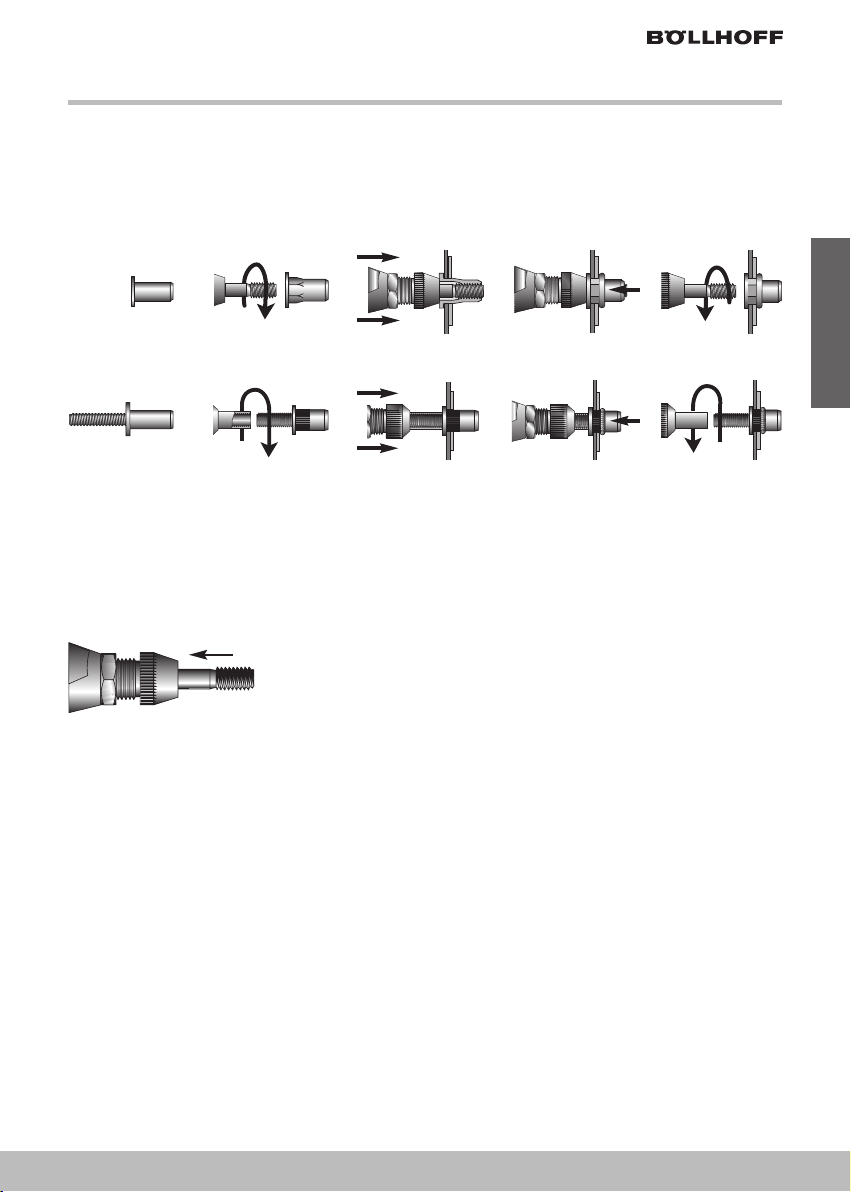
Crimp Spin off
Push pull Insert
Pulling methods
The “pulling method” comprises Push pull, Insert, Pull and Spin off cycles.
F
Call Cardinal Components to Order or for a Quote
9
English
1 - Operating principle and technical features of the device
Setting force (min - max) (kN) 3.00 –> 22.00*
( * > 18kN with appropriate accessory)
Setting capacity
Rivet Nut® M3 to M8*
Rivet Nut® Stud M4 to M8
(*M10 with appropriate accessory set)
Maximum stroke 7.0 mm
Weight of the tool 2.1 kg
Weight of the battery (2,6Ah) 0.3 kg
Battery Li-Ion / 14.4 V / 2.6 Ah
Environmental limitations of use 5°C - 40°C
IP egree of protection Vibration amplitude: 0.672 m/s²
Vibration 20
Noise emission Sound pressure level, LpA : 71.1 dB(A)
Sound power level, LwA : 82.1 dB(A)
Technical features
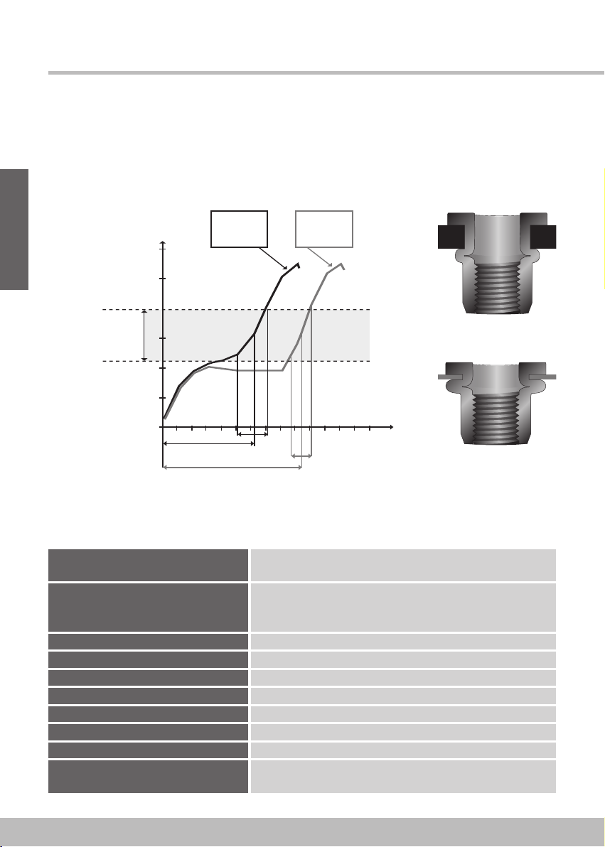
Setting force value
The recommended setting force is dependent on the combination of information coming from
Rivet Nut® parameters.
Rivet Nut® parameters
Maximum thickness (C1)
Minimum thickness (C2)
Setting effort range
= Force to obtain
a good setting
Force
Stroke
Tolerance
Stroke in
maximum thickness
Stroke in
minimum thickness
Tolerance
C1: setting
in maximum
thickness
C2: setting
in minimum
thickness
Minimum
Maximum
C1
C2
Call Cardinal Components to Order or for a Quote

English
10
Tool dimensions
Tool configurations and item number
Connection made
for Europe
Package with 1 battery 236 166 01 000
Connection made
for US
236 168 01 000
Package with 2 batteries 236 167 01 000 B4090-BOF
M3 M4 M5 M6 M8 M10
ez standard
ez spécifique
A
L
A
L
Contents of the case:
• 1 device without tooling
• 1 user manual
• 1 tool kit for tooling change
• 1 or 2 battery(ies)
• 1 battery charger
• 1 oil container
320 mm
Ø 28.5 mm
220 mm
L
330 mm
140 mm
A
62 mm
90 mm
Call Cardinal Components to Order or for a Quote
Assembling the device
11
English
2 - Preparation for use
SAFETY: BEFORE CARRYI G OUT A Y I TERVE TIO O THE DEVICE, DISCO ECT
THE BATTERY
03 04 05 06 08
–04 05 06 08
03 04 05 06 08
–04 05 06 08
236 113 XX 020 236 913 08 110
376 113 XX 020
M3 M4
236 913 10 019
–
08 10
–
X
MandrelAnvil
236 113 XX 030
376 113 XX 030
B4090-4076-0303
B4090-4076-0304
Fork and nose for studs &
force >18 kN (M8 & M10)
Fitting with special Rivet Nut® mandrels
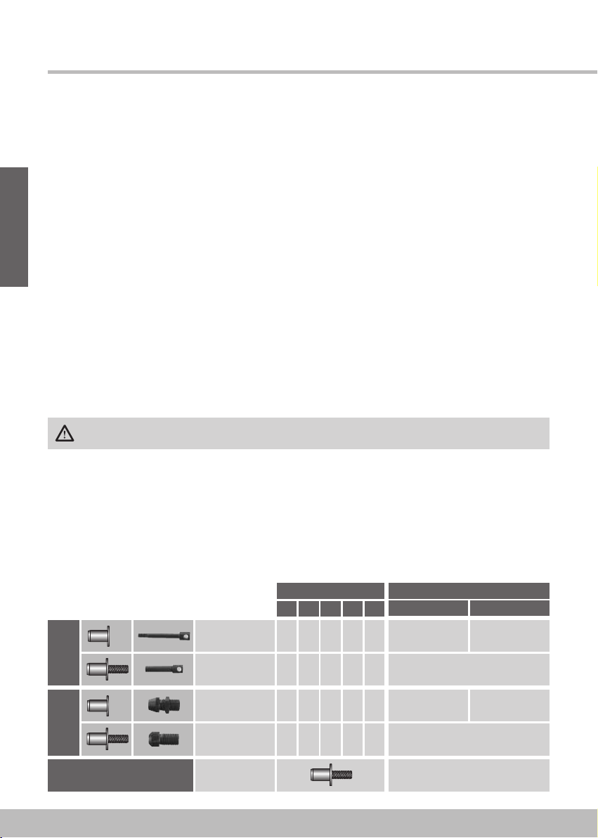
You have two assembly options:
• Fitting with special Rivet Nut® mandrels (recommended by BÖLLHOFF for extended
tool life)
• Fitting with standard capscrews
318 k
M5 M6 M8 M8 M10
18 22 k
Connection to the battery
The device is delivered with a 14.4 V / 2.6 Ah battery power supply.
To connect the battery to the tool:
• Grab the tool
• With your other hand, grab the battery so that the quick-release lever is facing downwards
• Insert the battery into place by sliding it upwards until the quick-release lever on the battery clicks.
It is required to use only the original battery to ensure proper operation of the device.
Charging the battery
• Store the battery charger in a cool and ventilated area.
• Plug the battery charger in the power outlet. SAFETY WAR I G: make sure the power supply
source is compatible with the requirements indicated on the product plate.
• Insert the battery it in the battery charger keeping it parallel. Do not force the battery since it should slide
easily in place. Any possible difficulty may indicate an incorrect alignment.
Call Cardinal Components to Order or for a Quote

12
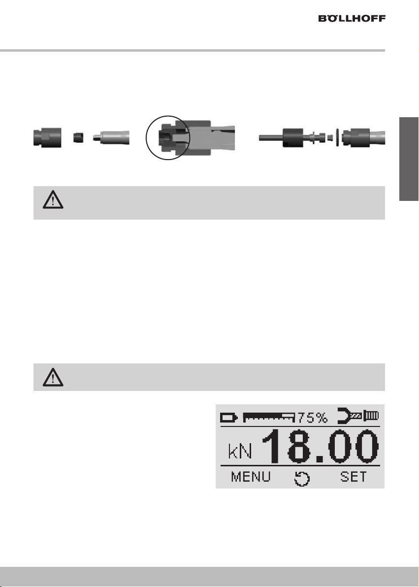
OK
OK
Based on the dimensions of the rivet, check that the following parts are present: mandrel ,
anvil , see diagram above.
• Remove the mandrel
• Refit the new mandrel by taking care to align the back side groove with the screwing driver
(see in figure 4). CAREFULL: grease (Multipurpose grease) has to be applyed between fork
and mandrel .
• Reposition the nose
• Retighten the nose to 15 Nm.
• Screw the new anvil inside the nose and lock it after adjusting the correct position thanks
to the nut.
THE BATTERY HAS TO BE DISCO ECTED WHE REPLACI G THE TOOLI G.
MA DREL (1) MOVES DURI G USE. AVOID CO TACT A D PAY THE UTMOST ATTE TIO .
OK
Mandrel Nose
Fork
Anvil
Figure 4 - Mandrel alignement
A
C D
E
B
Figure 3 - Fork and nose for studs & force >18 kN (M8 & M10)
21,5 mm
Force: 10 Nm
<>
12
ef. 23616600213
Call Cardinal Components to Order or for a Quote
13
English
2 - Preparation for use
Fitting with standard capscrew DI 912:
5 6 7
236 803 03 010 236 803 03040 M3 x 45 12.9
236 803 04040
236 803 05040
236 803 06040
NA
M4 x 55 12.9
M5 x 60 12.9
M6 x 65 12.9
M8 x 65 12.9
236 803 04 010
236 803 05 010
236 803 06 010
236 803 08 010
M3
M4
M5
M6
1+2+3+4
M8
COMMON
ADAPTATOR
8
46 7 52 1 3
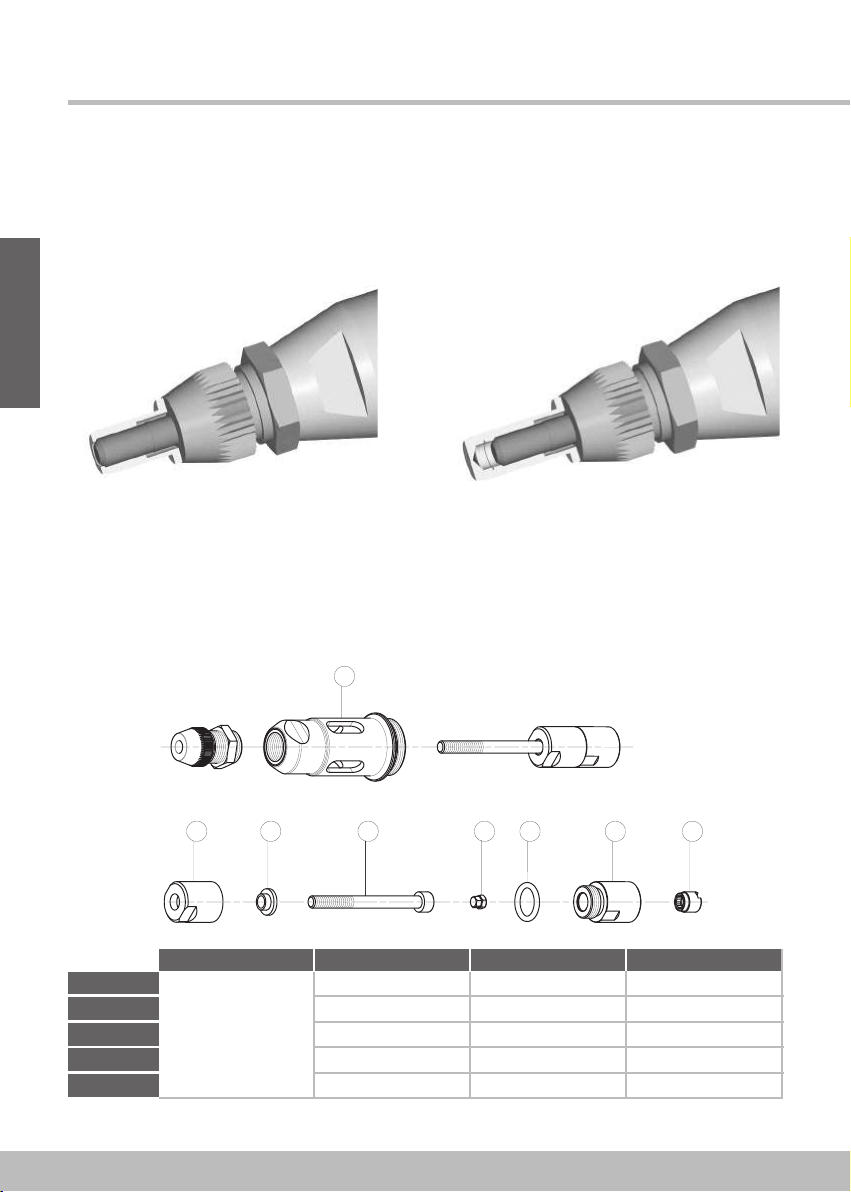
Adjusting the position of the anvil in relative to the mandrel
• The position of the anvil depends on the length of the Rivet Nut® before
setting.
• The position of the anvil should be adjusted as shown in figure 5.
• After adjustment, tighten the anvil locknut (2) to 10 Nm.
OPE Rivet Nut®SEALED Rivet Nut®
Flush rod on the end of the Rivet Nut®Thread root single-turn rod
Figure 5 - Adjustment of the anvil position
Call Cardinal Components to Order or for a Quote
14
English
Switching on the device
After inserting the battery, activate and release the trigger once, which is located on the front part
of the handle.
In this condition, the tool is able to operate immediately, i.e. approached to a rivet, it will carry out the
screwing on the nose. After this operation, the tool is ready to pull the rivet and the selected pull.
• Connect the battery
• Switch on the device
• To adjust the setting force value, press the
RIGHT button (SET) at any time and keep it
pressed for 2 seconds. The digits indicating
the setting value start to blink.
• Press the LEFT (-) and RIGHT (+) keys,
decreasing or increasing the value in 100N
steps, until the desired value is reached.
• Press the CENTER (O ) confirmation button
or wait 5 seconds without pressing any button.
Please note that when changing the force, the battery life also varies depending on the required pull:
a pull with less force will need less current, so the battery life will be longer and vice versa.
Adjustment of the setting force
For allowing the use of the commercial screw kit, this is required:
• To take off the fork which is installed on the standard tool
• Install the pieces pos 1 and 3.
Adjust the anvil (refer to page 20 for instruction).
THE BATTERY HAS TO BE DISCO ECTED WHE REPLACI G THE TOOLI G.
MA DREL (1) MOVES DURI G USE. AVOID CO TACT A D PAY THE UTMOST
ATTE TIO
AT THE TIME OF DELIVERY, THE DEVICE IS SET TO THE MI IMUM FORCE. THE
DEVICE EEDS TO BE SET FOR THE FIRST USE.
12 3
Call Cardinal Components to Order or for a Quote
15
English
2 - Preparation for use
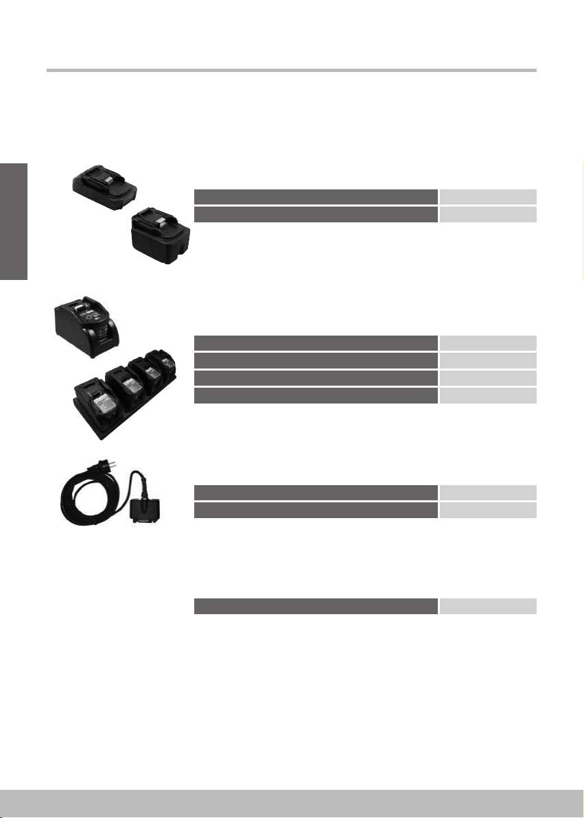
Options and accessories
The shart below lists the different accessories and options which are available for this tool.
B4090-4076-0350
B4090-4076-0351
Battery 14,4V 2,6AH
Battery 14,4V 4,0AH
Different capacities of battery
282 590 30353
282 590 30354
Battery loa er Solo EU
Battery loa er Solo US
Battery loa er Multi x4 EU
282 590 30355
Battery loa er Multi X4 US
Different loader
282 590 30356
282 590 30357
Continuous power supply 5m EU
Continuous power supply 5m US
Continuous power supply
236 166 00305
RK B4090 Support
Support for the tool
282 590 30352
Call Cardinal Components to Order or for a Quote

16
English
3 - Use
The device can be used in all positions, carried by hand or suspended.
Procedure for use
• Install the battery
• Switch the device on, by pulsing on the main trigger
• Position the Rivet Nut® on the mandrel. A light pressure starts the motor and causes the
automatic screwing of the Rivet Nut®, then the shutdown (Push-Pull system). Then insert
the Rivet Nut® into the hole.
• Alternatively, insert the Rivet Nut® into the hole, then push the mandrel against it in order
to activate the push-pull.
• Press the trigger and hold it until the mandrel has gone outside from the Rivet Nut® thread.
KEEP THE TRIGGER PRESSED FOR THE E TIRE DURATIO OF THE CYCLE.
IF THE TRIGGER IS RELEASED, THE I SERTIO IS OT CORRECT
Push pull (automatic) Insert Crimp Spin off (automatic)
Unscrew button
• If unscrewing is difficult, use the CENTER (UNSCREW / RESET) button.
To unscrew, hold the button down until the mandrel has fully gone outside from the Rivet
Nut® thread.
Call Cardinal Components to Order or for a Quote

17
English
3 - Use
Press the LEFT (MENU) button for 2 seconds to enter the programming menu. The LEFT button
moves the selection UP, the RIGHT button moves it DOWN, the CENTER button CONFIRMS.
The screen shows the main menu. Selectable options are:
I1. Language
Select the display language. Available options: French, English,
German, Italian, Spanish, Portuguese.
I2. Partial counter
Displays and allows resetting the partial cycle counter. Reset is
done by pushing LEFT and RIGHT buttons at the same time.
I3. Switch OFF time
Select the time after which the tool switches off, if no operation is
performed or no button is pressed (available options: 1, 5 or 10
minutes). In order to switch it on again, press the trigger briefly.
This time affects battery life.
Programming menu
The display screen appears after start up with the definition below:
Battery loa level (%)
Access to the menu pages
Information
of screwing state
Setting force level (in kN)
Access to the setting
force a justment screen
Manual comman for the
unscrewing / Acquitment button in case of fault
Call Cardinal Components to Order or for a Quote

Service sub-menu
Access by selecting option 6 of the main menu. Selectable options are:
18
English
I4. Start condition
Select the status of the tool at start.
Available options: Screwing done – Without condition.
I5. Force setting lock
By pushing on both + and - button at the same time, the setting is
getting lock, which means, that it will not be possible to modify the
setting force “SET” accessibility button, from production page.
Operation is reversible by proceeding the same way
I6. Service
Service sub-menu, see below.
IEXIT
For coming back to the production main page.
IOption 1: Identification
Displays Serial number, Firmware version, Total number of cycles.
These data are important in case you require assistance.
All our battery tool have been tested before delivery. Counter level
might be includes between 1500 cycles and 5000 cycles.
IOption 2: Buttons
Allows checking the functionality of the three display buttons and
the trigger. Differently from the other screens, to exit all three display
buttons shall be pushed at the same time.
Call Cardinal Components to Order or for a Quote

19
English
3 - Use
IOption 3: Sensors
Displays the status of the “Rest” sensor and the pressure sensor.
Rest sensor is the sensor checking the position of the main motor.
“ACT” means that the main motor is in the position ready to perform a
cycle. Pressure sensor: the value read by tis sensor is then translated
in the reading of the setting force. At rest, it might be possible that
residual pressure is present < 10 bars
IOption 4: Push-Pull view
The Push-Pull is calibrated at the factory, this page is giving access
to the sensor status.
IOption 5: Temperature View
Displays the temperature measured by three internal sensors.
For safety reasons, the machine stops working and displays an
error if an overheating occurs.
IOption 6: Battery
Displays the type and charge status of the battery. The tool will
stop, in case one of these temperature reach 75°C as a safety rule.
IOption 7: ext Service
Displays the number of cycles left before the next scheduled service.
A warning will be displayed when approaching and surpassing the
service threshold. The counter is defined for 250 000 cycles, refer
to the shart given on page 27. Reset of this counter can only be
done by Böllhoff staff. Maintenance service frequency is defined for
250 000 cycles.
IOption 8: Force set. Verify
The menu allows to adjust the convenient conditions for measuring
the real setting force applied on the mandrel using a force indicator
measurement devide (282 522 14000/00).
An offset < 400 N between measured value and consign appearing
on the display screen is considered as acceptable.
IOption 9: Restore defaults
This page will allow you to restore the setting as they were at the
initial preparation.)
IEXIT
For coming back to the “Option” main page.
Call Cardinal Components to Order or for a Quote

20
English
4 - Maintenance
Daily maintenance
The display screen appears after start up with the definition below:
Operation Frequency
Check the mandrel thread
Control the battery load level
Everyday
Everyday
Add grease inside the traction fork Each mandrel replacement
eplacement or cleaning of the mandrel
The Rivet Nut® should be screwed freely by hand Between 5,000 and 10,000 cycles
Oil draining and filling up Between 5,000 and 15,000 cycles
eplacement of the anvil
(If the internal diameter is > D + 0.5mm) Between 25,000 and 50,000 cycles
INSPECTION 1
Controling the main fonctions and performances
Every 250,000 cycles
eplacement of the oil and draining
Calibration of setting load
INSPECTION 2
Full maintenance of the setting head (seal parts, spring, …)
eplacement of the traction fork
Every 500,000 cycles
Call Cardinal Components to Order or for a Quote
Table of contents
Other Bollhoff Power Tools manuals


