Bolton Technical Victory Home Yagi User manual

User Manual
Bolton Victory Home (Yagi / Panel)
Bolton Victory Home (Omni / Panel)
www.boltontechnical.com
1-888-987-2658
BT459600-YP
BT459600-OP

Page 2Version 1 | May 9. 2023 | www.boltontechnical.com | 1.888.987.2658
HEY THERE!
Thanks for purchasing the Bolton Victory. You’ve taken the largest
step in ridding your life of poor cell signal. Each version of the Victory
kit has been carefully designed to provide the absolute best, most
user-friendly signal booster experience out there.
If you have any questions, feel free to give us a call! We’re US-based and eager to help.
Toll-free: 1-888-987-2658
International: 1-281-310-5929
Email: sales@boltontechnical.com
Operating Hours: Monday to Friday: 8am - 6pm CST

Page 3
TABLE OF CONTENTS
ABOUT US 2
HOW IT WORKS 4
WHAT’S IN THE BOX? 5
Bolton Victory Home (Yagi / Panel) 5
Bolton Victory Home (Omni / Panel) 5
INSTALLATION OVERVIEW 6
Antenna Types 6
Isolation and Necessary Separation 7
Antenna and Amplier Placement 8
INSTALLATION 10
IMPROVING PERFORMANCE 14
LED INDICATORS 15
TROUBLESHOOTING 16
SPECIFICATIONS 17
CONSUMER GUIDELINES 19
WARRANTY 20

Page 4Version 1 | May 9. 2023 | www.boltontechnical.com | 1.888.987.2658
1. How It Works
Every signal booster kit is made up of three key components:
• Outside antenna(s) - Captures cell signal from nearby cell tower
• Signal booster, or amplier – Boosts the captured signal
• Inside antenna(s) - Broadcasts the boosted signal indoors
These components are connected by coaxial cable.
There are two main issues people have when installing the Bolton Victory:
proper placement of their antennas, and nding usable signal to boost.
We might as well get the biggest problem out of the way now: if you go all
over your property and cannot make a call or get reception of any kind, the
Bolton Victory will not work for you. The booster requires existing signal to
function. Without that, it’s little more than a paperweight. Please call us at
1-888-987-2658 for a return.
Antenna locations and signal quality matter more than anything.
COMPATIBILITY
The Bolton Victory works with:
AT&T
Verizon
T-Mobile
US Cellular
All other US carriers and MVNOs

Page 5
2. What’s in the Box?
The core of each Bolton Victory kit is – you guessed it – a Bolton Victory cell
phone signal booster. However, the rest of the contents in your box will vary
depending on the specic kit purchased.
We recommend getting started by unpacking all contents of the box. For
missing or damaged items, contact your reseller.
2.1 Bolton Victory Home (Yagi / Panel) - BT459600-YP
1x Bolton Victory Signal Booster BT459600
1x Quicksilver 5G 50 Ohm Yagi Antenna BT151038
1x Indoor Board 50 Ohm Panel Antenna BT512501
50 ft RG-6 Cable – White Jacket – F-Male to F-Male SC-RG6-50
20 ft BT240 Cable – White Jacket – N-Male to N-Male SC-004-20-NN
1x Connector F-Female to N-Male BT512020
1x Power Supply BT459792
2.2 Bolton Victory Home (Omni / Panel) - BT459600-OP
1x Bolton Victory Signal Booster BT459600
1x All-Rounder 50 Ohm Omni Antenna BT512372
1x Indoor Board 50 Ohm Panel Antenna BT512501
50 ft RG-6 Cable – White Jacket – F-Male to F-Male SC-RG6-50
20 ft BT240 Cable – White Jacket – N-Male to N-Male SC-004-20-NN
1x Connector F-Female to N-Male BT512020
1x Power Supply BT459792

Page 6Version 1 | May 9. 2023 | www.boltontechnical.com | 1.888.987.2658
3. Installation Overview
3.1 Antenna Types
These are the antenna types which are kitted with the Bolton Victory.
OUTDOOR
All-Rounder (Omnidirectional) – Gathers signal in a 360 degree radius. Easy to
install, but provides less power than a Yagi antenna. Works best in areas with
strong outdoor signal.
Quicksilver (Directional Yagi) - Gathers signal from the direction you point.
Requires aiming, but provides more power to a system.
Outdoor Board (Directional Panel) - Captures signal in a 45 degree radius.
Provides more boost than an omni antenna, but less than a yagi. Easier to
mount and install indoors or in small areas, such as apartments.
INDOOR
Indoor Board (Directional Panel) – Projects boosted signal in a 45 degree
radius. Provides more power than a dome antenna, but can be trickier to
implement effectively. Best for hallways and places where projecting signal.

Page 7
3.2 Isolation and Necessary Separation
Isolation is a measure of separation between the Indoor and Outdoor
antennas.
Placing your indoor and outdoor antennas too close together can cause
“oscillation.” Oscillation is a type of feedback that occurs if the gain of the
system is higher than the isolation.
The more isolation between the outside and indoor antenna you have, the
more the VICTORY will be able to amplify your signal, and the better your
signal will be inside the building. As a general rule, you should strive to have
either 50 feet of horizontal distance or 20 feet of vertical distance between
the outdoor and inside antennas.
One of the two major consideration of where to place your antennas should be
to avoid as much isolation as possible.

Page 8Version 1 | May 9. 2023 | www.boltontechnical.com | 1.888.987.2658
3.3 Antenna and Amplier Placement
OUTDOOR ANTENNA PLACEMENT
Finding the best location possible for the Outdoor Antenna is critical. There are
two things you need to consider:
1. Isolation from the Indoor Antenna(s)
2. Signal quality
If you end up with a situation where you have to prioritize avoiding oscillation
over somewhat higher quality signal, prioritize avoiding oscillation. However,
remember – if you’ve only got good quality signal in one area, that’s where the
outdoor antenna should be placed, no matter what.
HOW TO MEASURE SIGNAL QUALITY
For some buildings, the location with the best signal may be on top of the roof.
In others, the best location is the side of the building. The best way to nd out
is to test.
There are two ways you can measure signal quality:
1. Look at the number of bars (easiest, but least reliable method)
2. Download the OpenSignal app for iPhone or the Network Cell Info Lite
app for Android (best method)
To nd the best Outdoor Antenna location: walk around the perimeter of your
building with your phone, and if you can, get up on the roof. You’re looking
for a location with good SINR (ideally above 5 dB) and good isolation from the
indoor antenna locations.
Page 9
INDOOR ANTENNA PLACEMENT
The signal from your booster is strongest where it is broadcast. For best
results, place the indoor antenna(s) near where you’re most likely to use your
cellular devices.
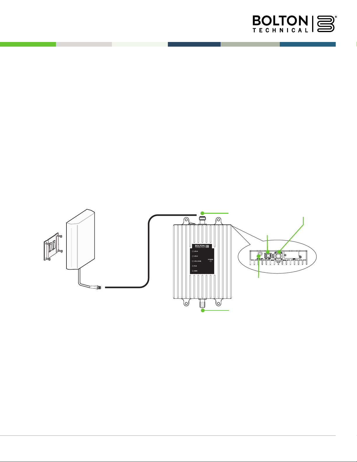
AMPLIFIER PLACEMENT
Your Bolton Victory should be placed in a cool, dry area with access to a
power source. For best results, use an uninterruptible power supply and surge
protector to allow for its continued function during blackouts.
Connector to Inside Antenna
Connector to Outside Antenna
Power Jack
Power Switch

Page 10 Version 1 | May 9. 2023 | www.boltontechnical.com | 1.888.987.2658
4. Installation
Step 1: Find the Area with the Strongest Outside Signal
Using your phone, identify the outside location with the strongest signal for
placement of your outside antenna. Generally, this is found above the rooine
on the side facing your nearest cell tower and as high as possible – where the
antenna can ‘see’ your cell tower. To nd the location of your carrier’s closest
cell tower, go to www.cellmapper.net.
The coverage area provided by the booster is directly related to the strength of
incoming signal. Mounting the outside antenna where the signal is strongest
will provide the best results.
See your included “Quick Start” guide for a complete guide on how to read
signal effectively.
Step 2: Install the Outside Antenna
After identifying the area with the strongest signal, choose the surface where
you will mount your outside antenna.
The location should allow for sufcient separation between the outside
antenna and inside antenna. Vertical separation is preferred as it is more
effective than horizontal separation. The minimum separating distance
recommended is 25 vertical ft or 50 ft horizontal.

Page 11
FOR ALL-ROUNDER
The All-Rounder is omni-directional antenna, able to receive and send signal
in a 360-degree radius. This makes it easier to install than a yagi or panel. The
provided hardware allow for either a surface or pole-mount.
1. Using vertical plate of bracket, mark position of desired placement.
The omni antenna should be mounted in an upright position.
2. Unscrew nut from end of stucco screw and remove it along with lock
washer and regular washer.
3. Place vertical L-bracket plate into desired location and tap the
screws, head rst, along with sleeve, into stucco ½ to 5/8 inches
deep into place.
4. In this order, place washer, lock washer and nut on each screw and
tighten until secure. When tightening screw, sleeve will expand to
secure plate.
5. Use provided screws to secure antenna base onto horizontal plate
6. Connect antenna to one end of the provided RG6 cable and
tighten the connection. Run the cable along route to planned
location of booster.
Screws
L-Bracket
Bracket Hardware
Page 12 Version 1 | May 9. 2023 | www.boltontechnical.com | 1.888.987.2658
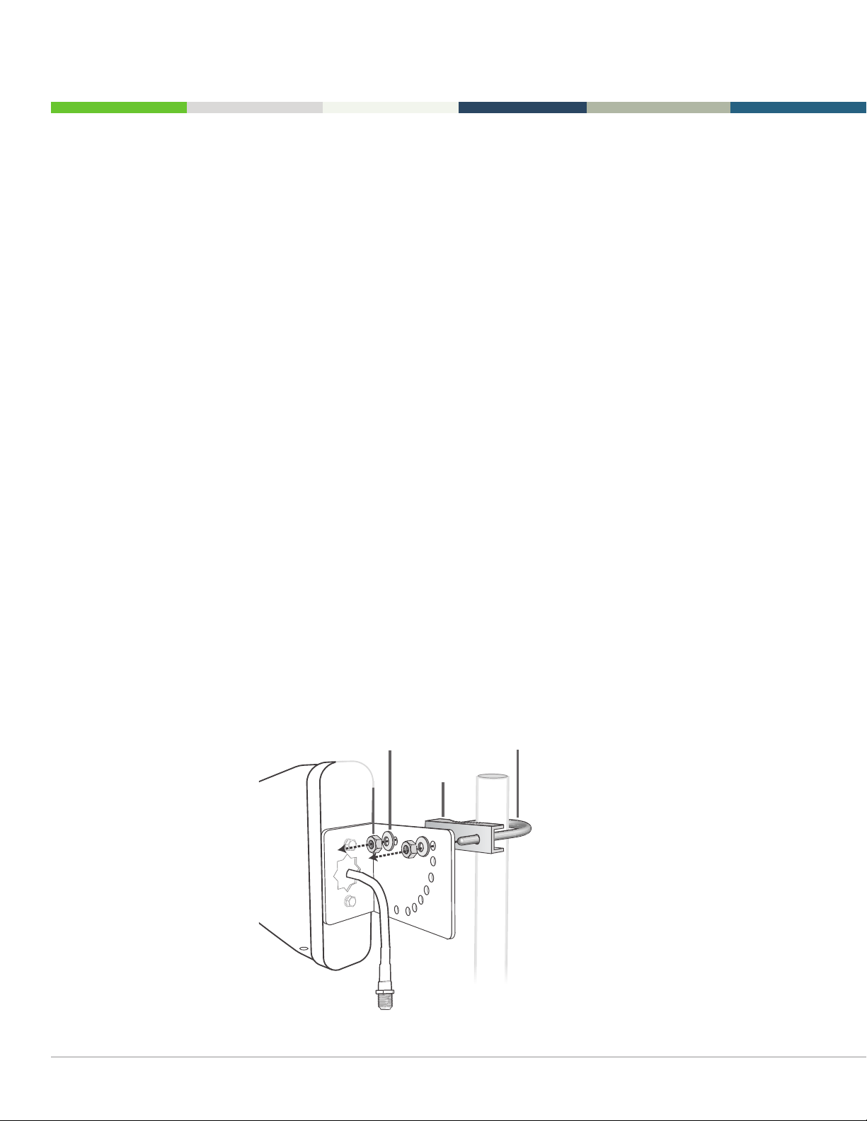
FOR QUICKSILVER:
Before installing, note that the Quicksilver antenna should be mounted on a
pole or pipe (not included) at the highest possible location above the
rooine – at least 25 ft above the indoor antenna – aimed in the direction of
your nearest cell tower. To nd the location of your carrier’s closest cell tower,
go to www.cellmapper.net.
Ensure the mounting area has at least a 3 ft radius clear of obstructions, other
radiating elements and metal objects such as pipes or metal siding and orient
the antenna with the drip hole at the bottom.
Once you have identied your install location, assemble the u-bolt, bracket,
nuts and washers onto a pole (sold separately) as shown in the illustration.
Keep the connections loose enough to allow the antenna to rotate until the
optimum direction is found.
Once the outside antenna is secured to a pipe or pole, connect antenna to
one end of the provided RG6 cable and tighten the connection. Run the cable
along route to planned location of your booster.
Nut
Washer U-bolt
Bracket

Page 13
FOR INDOOR BOARD
Bolton’s Indoor Board antennas are directional with a 120-degree reach. They
should be mounted facing the area signal is needed and away from the
outdoor antenna.
Mount on a vertical surface that is the approximate height of normal cell
phone use. Besides the antenna itself, parts include mounting equipment for a
at vertical surface.
1. Using plate, mark position of desired screw placement.
2. Screw mounting plate into place with the slide panel protruding
toward you.
3. Slide antenna securely onto mounting plate.
4. Connect antenna to one end of the BT240 cable and run to planned
location of your booster.
5. Place the booster on a at surface or mounted to a wall and connect
the remaining end of the BT-240 cable to booster port marked
INSIDE. Included connectors may be required to fully connect all
cables to booster.

Page 14 Version 1 | May 9. 2023 | www.boltontechnical.com | 1.888.987.2658
5. If You Want to Improve
Performance or Coverage
To improve performance, focus on the two key areas: nding an area with
higher quality outdoor signal, and increasing antenna separation.
If using an omni outside antenna, upgrade to a directional yagi antenna that
can be aimed toward your closest tower.
To increase interior coverage, consider purchasing more inside antennas
(you’ll need more cable and a splitter as well). Only recommended if the signal
strength at your outdoor antenna is strong.
Coax Cable (50 ft.)
Power Supply
Signal Booster
Inside Antenna
Outside Antenna
Coax Cable (20 ft)

Page 15
6. LED Indicators
LED COLOR LED CONDITION RESOLUTION
OFF Part of normal operation. Light is off while band is active.
Yellow Solid Part of normal operation. Indicates the frequency band
is not being used. After a period of time, if there’s no
activity, that band will go into sleep mode.
Yellow Flashing Part of normal operation. Indicates that the Automatic
Gain Control (AGC) is self-adjusting.
Red Flashing Indicates that the booster is receiving too much signal
which could cause the affected band to automatically
turn off. When this happens:
1. For kits using an OMNI outside antenna, relocate
the outside antenna to a location where the siganl is
weaker.
2. For kits using a YAGI outside antenna, turn the antenna
in short increments away from the signal source.
3. Increase the separation between antennas (additional
vertical separation works best).
4. Add an inline attenuator to the cable coming inot the
outside port of the booster.
5. Though not desirable as amplication will not
be optimum, lower the dB gain setting in small
increments until the light turns off or ashes yellow.
Red Solid The frequency band is off.
If a red light has been ashing for an extended time
due to too much signal, that frequency band will
display a solid red light indicating that the circuitry for
that frequency band has been turned off. This can also
happen when the gain dial for a frequency band has
been turned all the way down.
Yellow / Red Alternately Flashing Self-oscillation has been detected and to prevent it, one
or more of the frequency bands have shut down.
If this happens: First, try increasing the separation
between the inside and outside antennas. If your booster
kit uses directional antennas (example: outside Yagi
antenna and inside panel antenna), ensure that they are
facing away from each other.

Page 16 Version 1 | May 9. 2023 | www.boltontechnical.com | 1.888.987.2658
7. Troubleshooting
If you have any questions, feel free to give us a call! We’re US-based and
eager to help.
Toll-free: 1-888-987-2658
International: 1-281-310-5929
Email: support@boltontechnical.com
Operating Hours:
Monday to Friday: 8am - 6pm CST
PROBLEM RESOLUTION
Signal booster has no power Connect the power supply to an alternate power source.
Verify the power source is not controlled by a switch that
has removed power from the outlet.
If it remains OFF, contact tech support at: 1-888-987-2658
or support@boltontechnical.com
After completing installation, Verify that cable connections are tightly
indoor signal coverage has tted to the booster and antenna.
not improved Try further separating the booster and antenna.
Verify that there is usable signal where the antenna
is placed.
Note: Bars are not always a reliable measure of signal. The
best way to conrm signal coverage is the ability to place
and hold a call.

Page 17
8. Specications
SIGNAL BOOSTER
Model Victory
Uplink Frequency Range (MHz) 698-716 / 776-787 / 824-849 / 1850-1915 / 1710-1755
Downlink Frequency Range (MHz) 728-746 / 746-757 / 869-894 / 1930-1995 / 2110-2155
Maximum Gain 72 dB
Supported Standards CDMA, WCDMA, GSM, EDGE, HSPA+, EVDO, LTE and
all cellular standards
Max Uplink Power 26.0 dBm
Input Impedance 75Ω donor port / 50Ω server port
Noise Figure 8 dB
AC Input Input AC110V, 60 Hz; Output DC 5-15V
Maximum Output Power 1 Watt EIRP
Cable RG6 / BT-240
RF Connectors F-Female (outdoor) / N-Female (indoor)
Power Consumption <15W
Operation Temperature -4° to +158°F / -20° to +70°C
Dimensions 7.875 x 5 x 1.188 inches
Weight 2 LB 3 oz. / 1 kg
Certications FCC ID: RSNF4HOME

Page 18 Version 1 | May 9. 2023 | www.boltontechnical.com | 1.888.987.2658
KITTING
Component Product Gain / Loss Note
Number
LTE-A LTE-V Cellular PCS AWS
707MHz 731MHz 1900MHz 1700 /
2100 MHz
Outdoor BT151038 7.5±1 dBi 7.5±1 dBi 9±1 dBi 9±1 dBi 9±1 dBi
Antenna BT512372 3.5 dBi 3.5 dBi 3 dBi 4 dBi 4 dBi
BT512365 6.5 dBi 6.5 dBi 6.5 dBi 8 dBi 8 dBi
Outdoor SC-RG6-50 3.32 dB 3.32 dB 3.75 dB 6.42 dB 6.22 / 50 ft or
Cable 6.68 dB longer
Inside SC-004-20-NN 2.06 dB 2.06 dB 2.29 dB 3.56 dB 3.36 dB / 20 ft or
Cable 3.76 dB longer
Inside BT512501
Antenna SC-123W 1.2 dBi 1.2 dBi 3 dBi 5 dBi 4 dBi /
5 dBi
* Warning: Unauthorized antennas, cables, and/or coupling devices are prohibited by FCC regulations.
Changes or modications not expressly approved by Bolton Technical could void the user’s authority to
operate the equipment.
* FCC 27.50(d)(4) Statement: Fixed, mobile and portable (hand-held) stations operating in the 1720-1755
MHz band are limited 1 Watt EIRP. Fixed stations operating in this band are limited to a maximum antenna
height of 10 meters above ground. Mobile and portable stations operating in this band must employ a
means for limiting power to the minimum necessary for successful communications.

Page 19
9. Consumer Guidelines
This is a CONSUMER device.
BEFORE USE, you MUST REGISTER THIS DEVICE with your wireless provider
and have your provider’s consent. Most wireless providers consent to the use
of signal boosters. Some providers may not consent to the use of this device
on their network. If you are unsure, contact your provider.
You MUST operate this device with approved antennas and cables as specied
by the manufacturer. Antennas MUST be installed at least 20 cm (8 inches)
from (i.e., MUST NOT be installed within 20 cm of) any person.
You MUST cease operating this device immediately if requested by the FCC or
licensed wireless service provider.
WARNING: E911 location information may not be provided or may be
inaccurate for calls served by using this device.
This device may operate in a xed location only, for in-building use.
This device complies with Part 15 of the FCC Rules. Operation is subject to the
following two conditions: (1) this device may not cause harmful interference,
and (2) this device must accept any interference received, including
interference that may cause undesired operation.

Page 20 Version 1 | May 9. 2023 | www.boltontechnical.com | 1.888.987.2658
10. Warranty
In the event of a manufacturing error, Bolton Technical offers a 2-year
warranty. Should you choose to take advantage of this, please call us toll-free
at (1-888-987-2658) between the hours of 8AM – 6PM CST. We will provide an
RMA (return merchandise authorization) number. You will be responsible for
return shipping. A replacement product will be shipped to you as soon
as possible.
This warranty does not apply to any product determined by Bolton Technical
to have been subjected to misuse, abuse, neglect, or mishandling that alters
or damages the product’s physical or electronic properties.
This manual suits for next models
3
Table of contents
Other Bolton Technical Extender manuals


