Bona Power Scrubber User manual

REV 3/11

English 2
To reduce the risk of fire, electric
shock, or injury:
–Do not leave appliance when
plugged in. Unplug from outlet when
not in use and before servicing.
–TO REDUCE THE RISK OF ELEC-
TRIC SHOCK-USE INDOORS
ONLY
–Do not allow to be used as a toy.
Close attention is necessary when
used by or near children.
–Use only as discribed in this manu-
al. Use only manufacturer`s recom-
mended attachments.
–Do not use with damaged cord or
plug. If appliance is not working as it
should, has been dropped, dam-
aged, left outdoors, or dropprd into
water, return it to a service center.
–Do not pull or carry by cord, use
cord as a handle, close a door on
cord, or pull cord around sharp edg-
es or corners. Do not run appliance
over cord. Keep cord away from
heated surfaces.
–Do not unplug by pulling on cord. To
unplug, grasp the plug, not the cord.
–Do not handle plug or appliance
with wet hands.
–Do not put any object into openings.
Do not use with any opening
blocked; keep free of dust, lint, hair,
and anything that may reduce air
flow.
–Keep hair, loose clothing, fingers,
and all parts of body away from
openings and moving parts.
–Turn off all controls before unplug-
ging.
–Use extra care when cleaning on
stairs.
–Do not use to pick up flammable or
combustible liquids, such as gaso-
line, or use in areas where they may
be present.
–Connect to a properly grounded
outlet only. See Grounding Instruc-
tion.
This appliance must be grounded. If it
should malfunction or breakdown,
grounding provides a path of least re-
sistance for electric current to reduce
the risk of electric shock. This appli-
ance is equipped with a cord having an
equipment-grounding conductor and a
grounding plug. The plug must be in-
serted into an appropriate outlet that is
properly installed and grounded in ac-
cordance with all local codes and ordi-
nances.
Improper connection of the equipment
grounding conductor can result in a risk
of electric shock. Check with a qualified
electrician or service person if you are
in doubt as to whether the outlet is
properly grounded. Do not modify the
plug provided with the appliance-if it
will not fit the outlet, have a proper out-
let installed by a qualified electrician.
This appliance is for use on a nominal
120-volt circuit and has a grounding at-
tachment plug that looks like the plug il-
lustrated in illustration A. Make sure
that the appliance is connected to an
outlet having the same configuration as
the plug. No adaptor should be used
with this appliance.
1 Grounded outlet
2 Grounded outlet Box
3 Grounded Pin
Safe operation is in the responsibility of
the operator.
The operator shall be familiar with the
operation and function of all controls
and instruments before operating the
unit.
Before operating the unit, operators
shall have read and be familiar with the
operator’s manual for the particular unit
being operated and they shall also
abide by the safety rules and practices
in the following paragraphs.
Before operating any unit, the operator
shall be familiar with unusual operating
conditions which may require addition-
al safety precautions or special operat-
ing instructions.
Before starting to operate the unit be in
operating position.
Do not start or operate the unit, any of
its functions or attachments, from any
place other than from the designated
operators position.
Before leaving the operator’s position:
A bring the unit to a complete stop;
B if the unit must be on an incline,
block the wheels.
Maintain a safe distance from the edge
of ramps, platforms, and other similar
working surfaces.
Do not add to, or modify the unit.
Do not block access to fire aisles, stair-
ways or fire equipment.
IMPORTANT SAFETY IN-
STRUCTIONS
READ ALL INSTRUCTIONS
BEFORE USING.
WARNING
WARNING
SAVE THESE INSTRUCTIONS
GROUNDING INSTRUCTIONS
WARNING
CONNECT TO A PROPERLY
GROUNDED OUTLET ONLY
OPERATINGSAFETYRULES
AND PRACTICES
Operator Responsibility
General

3English
If the unit is found to be in need of re-
pair or in any way unsafe, or contrib-
utes to an unsafe condition, the matter
shall be reported immediately to the us-
er’s designated authority, and the unit
shall not be operated until it has been
restored to safe operating condition.
If during operation the unit becomes
unsafe in any way, the matter shall be
reported immediately to the user’s des-
ignated authority, and the unit shall not
be operated until it has been restored
to safe operating condition.
Do not make repairs or adjustments
unless specifically authorized to do so.
Operation of the unit may be hazard-
ous if maintenance is neglected or re-
pairs, rebuilds, or adjustments are not
performed in accordance with the man-
ufacturer’s design criteria. Therefore,
maintenance facilities (on or off pre-
mises), trained personnel, and detailed
procedures shall be provided.
Maintenance and inspection of the unit
shall be performed in conformance with
the following practices:
A a schedules planned maintenance,
lubrication, and inspection system
shall be followed; consult the manu-
facturer’s recommendations.
B only trained and authorized person-
nel shall be permitted to maintain,
repair, adjust, and inspect the unit,
and in accordance with manufactur-
er’s specifications.
Avoid fire hazards and have fire protec-
tion equipment present in the work ar-
ea. Do not use open pans of fuel or
flammable cleaning fluids for cleaning
parts.
Any unit not in safe operating condition
shall be removed from service.
Fire Prevention: The unit shall be kept
in a clean condition and reasonably
free of lint, excess oil, and grease.
Noncombustible agents are preferred
for cleaning the unit. Flammable liquids
[those having flash points at or above
100°F (37,8°C)] are not allowed. Pre-
cautions regarding toxicity, ventilation,
and fire hazard shall be appropriate for
the agent or solvent used.
Nameplate Visibility: The unit type des-
ignations as shown on the nameplate
and the type markers shall not be cov-
ered over with paint so that their identi-
fication information is obscured.
Please read and comply
with these instructions prior
to the initial operation of your appli-
ance. Retain these operating instruc-
tions for future reference or for
subsequent possessors.
Safety instructions 4
Function 4
Proper use 4
Environmental protection 4
Operating elements 5
Before Commissioning 5
Operation 6
Maintenance and care 7
Troubleshooting 7
Specifications 9
Accessories 10
Warranty 10
Spare parts 10
Before using the appliance for the first
time, read and observe these operating
instructions and the accompanying
brochure: Safety information for brush
cleaning units and spray-extraction
units, 5.956-251.
The following symbols are used in this
operating manual:
Danger
Indicates an immediate threat of dan-
ger. Failure to observe the instruction
may result in death or serious injuries.
몇Warning
Indicates a possibly dangerous situa-
tion. Failure to observe the instruction
mayresult in lightinjuriesordamage to
property.
Note
Indicates useful tips and important in-
formation about the product.
The appliance is used for the wet
cleaning or polishing of level floors.
Two brush rollers located opposite of
each other clean the floor by means of
the added detergent liquid. A working
width of 16 in. (400 mm) and a capacity
of 10.5 qts (10 l) each of the fresh and
dirt water reservoirs allow for effective
cleaning.
The power supply operation allows a
high capacity without a restriction of the
working time.
Note
The appliance can be equipped with
various accessories depending on the
cleaning task. Please request our cata-
logue or visit us on the Internet.
Use this appliance only as directed in
these operating instructions.
–The appliance may only be used for
the cleaning of hard surfaces that
are not sensitive to moisture and
polishing operations.
The application temperature ranges
from 41°F1 to 104°F (+5°C to
+40°C).
–The appliance is not suited for the
cleaning of frozen grounds (e.g. in
cold stores).
–The appliance may only be
equipped with original accessories
and spare parts.
–The appliance has been designed
for the cleaning of floors inside or or
covered surfaces. With respect to
other applications the usage of al-
ternative brushes must be checked.
–The appliance is not intended for
the cleaning of public traffic routes.
Operator care of the unit
MAINTENANCE AND RE-
BUILD PRACTICES
FIRE SAFETY STANDARD
Contents
Safety instructions
Symbols
Function
Proper use
Environmental protection
The packaging materials
are recyclable. Please do
not throw packaging in the
domestic waste but pass it
on for recycling.
Old units contain valuable
recyclable materials. Batter-
ies, oil and similar substanc-
es may not be released into
the environment. Therefore
please dispose of old units
through suitable collection
systems.

English 4
1 Lock for solution tank
2 Switch for brush drive
3 Solution switch
4 Solution hose
5 Dust filter (suction)
6 Lock of pushing handle
7 Release button for the transport
wheel
8 Bearing wheel
9 Push handle
10 Strain relief clamp
11 Support of the transport wheel
12 Clip
13 Solution tank
14 Recovery tank
15 Push-button for squeege change
16 Shut off float
17 Button for brush change
18 Chassis
19 Squeegee
20 Brushes
21 Rotating handle for brush contact
pressure
22 Pedal to lower squeegee
23 Electrical plug
24 Carrying handle for recovery tank
25 Solution tank cover
ÎSlide the upper slider half onto the
lower slider half.
몇Warning
Riskofdamage.Donot pinchthecable
during the installation.
ÎAlign the borings (2 possible height
adjustments).
ÎConnect the slider halves to the lock
screws, discs and star grips.
ÎFasten the cable to the slider using
clips.
ÎInsert the transport wheel axles into
the borings on the appliance and
lock them.
The brushes must be installed before
the initial operation (see "Maintenance
works").
Operating elements
24
25
Before Commissioning
Installing the pushing handle
Installing the transport wheels
Installing the Brushes
5English
Note
To take the brush drive out of opera-
tion, immediately release brush drive
switch.
몇Warning
Risk of damage. Only use the recom-
mended detergents. With respect to
different detergents the operator bears
the increased risk regarding the opera-
tional safety and danger of accident.
Only use detergents that are free from
solvents, hydrochloric acid and hydrof-
luoric acid.
Note
Do not use highly foaming detergents.
Observe the meter mixing notes.
Recommended detergents:
ÎOpen the cover of the solution tank.
ÎPour in water/detergent mixture.
Maximum temperature of the liquid
120°F (50°C)
Note
The solution tank cover can be used to
meter the detergent. The capacity of
thecoveruptothemark represents1%
of the fresh water reservoir capacity.
ÎClose the cover of the solution tank.
ÎPlace the slider vertically.
ÎPosition the rotary handle for the
brush contact pressure in the drive
position.
ÎUse the pushing handle to push the
appliance to the place of use.
ÎPlace the slider vertically and tilt the
lock up.
ÎInstall the transport wheels.
ÎTilt the appliance to the side and
drive it to the place of use on its
transport wheels.
If the transport wheels hinder the use of
the appliance:
ÎPress the transport wheel release
button and pull the transport wheel
out.
ÎInsert the transport wheels into their
holder until they stop.
ÎPlace the slider vertically.
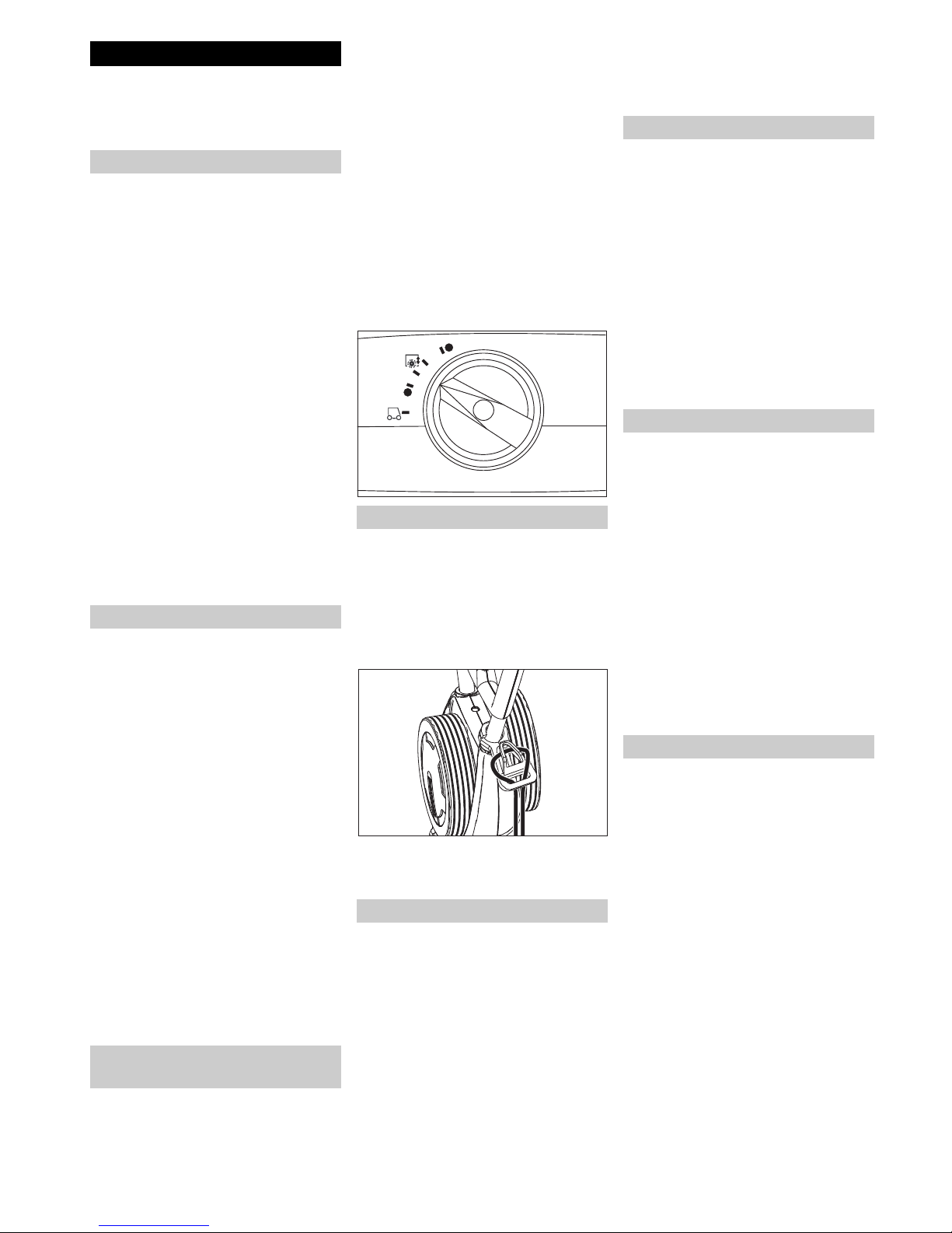
ÎAdjust the rotary handle of the
brush contact pressure to the de-
sired value.
Note
Carry out the initial cleaning attempts
with less contact pressure. Increase
contact pressure step-by-step until the
desired cleaning result is achieved. A
correct setting of the contact pressure
reduces the wear and tear of the brush-
es.
The brush drive is switched off when
there is overload.
When cleaning with microfibre rollers,
the contact pressure must not be ad-
justed higher than the position men-
tioned below. With a higher contact
pressure, there is a danger of destroy-
ing the microfibre rollers.
Danger
Checkthemainscablesofthemachine
each time before using the machine to
see that it is not damaged. Never op-
erateamachinewithdamagedcables.
Get the damaged cables replaced by
an electrician.
ÎInsert the looped end of the exten-
sion cable in the strain relief hook.
ÎPlug in the mains plug.
ÎIf the detergent solution is to be vac-
uumed off after the cleaning pro-
cess, use squeegee lowering pedal.
ÎSwivel the slider toward the opera-
tor - the chassis is retracted and the
brushes touch the floor.
ÎTurn on the brushes by using the
switch for the brush drive.
ÎTurn on the brush irrigation by using
the switch for the detergent solu-
tion.
ÎMove the appliance over the sur-
face to be processed by the slider.
몇Warning!
Risk of damage to the floor covering.
Do not operate the appliance on the
spot.
ÎSwivel the slider toward the opera-
tor - the chassis is retracted and the
brushes touch the floor.
ÎTurn on the brushes by using the
switch for the brush drive.
ÎMove the appliance over the sur-
face to be processed by the slider.
몇Warning!
Risk of damage to the floor covering.
Do not operate the appliance on the
spot.
Note
To polish under furniture, remove the
solution tank and recovery tank.
ÎRelease the switch for detergent so-
lution.
ÎPush the appliance forward for an-
other 3-6 ft (1-2 m) to draw off resid-
ual water.
ÎRelease the brush drive button.
ÎPress the pedal to lower the vac4u-
um bar.
ÎPlace the slider vertically - the
brushes are elevated.
ÎDisconnect the mains plug.
몇Warning
Danger of deforming the brushes.
When switching off the appliance, take
the load off the appliance by placing
the slider vertically.
ÎOpen the locks for the Solution
tank.
ÎTilt the carrying handle for the re-
covery tank towards the side.
ÎLift up the solution tank and carry it
to the disposal site.
몇Warning
Please observe the local provisions re-
garding the wastewater treatment.
ÎRemove the cover of the solution
tank and pour out the liquid via the
notch.
Operation
Chemical filling
Driving to the Place of Use
Short distances on even surfaces
Longer distances on uneven surfac-
es
Adjust the brush contact pres-
sure
Establish mains contact
Cleaning
+
-
Polishing
Shutting Down the Appliance
Emptying the Solution tank

English 6
Note
If the recovery tank is full the float clos-
es the suction channel. The suction op-
eration is interrupted. Empty the
recovery tank.
ÎRemove the solution tank, as de-
scribed above.
ÎLift up the recovery tank and carry it
to the disposal site.
몇Warning
Please observe the local provisions re-
garding the wastewater treatment.
ÎPour out dirty water.
ÎRinse the recovery tank with clear
water.
ÎIf you want to transport the appli-
ance on a vehicle secure it from
slipping.
To reduce the required space, the
pushing handle can be folded or disas-
sembled:
ÎRelease the star grips of the push-
ing handle fastening.
ÎUnscrew the star grips, remove the
screws and take off the upper push
handle half.
Danger
Risk of injury!
Pull the plug from the mains before car-
rying out any tasks on the appliance.
몇Warning
Risk of damage to the appliance on ac-
count of water leakage. Drain out dirty
water and the remaining free water be-
fore wokring at the machine.
몇Warning
Riskof damage. Donotwashdownthe
appliance with water and do not use
aggressive detergents.
ÎPour out dirty water.
ÎRinse the recovery tank with clear
water.
ÎEmpty the solution tank.
ÎFill the solution tank with clear water
and rinse the appliance to avoid
residue buildup.
ÎRemove the remaining water from
the solution tank.
ÎCheck the seal in the ball valve in
the solution tank.
ÎCheck the lint filter, clean if required
ÎLet the tanks dry prior to closing
them to prevent odor.
ÎClean the outside of the appliance
with a damp cloth which has been
soaked in mild detergent.
ÎClean the squeegee, check for wear
and replace the squeegee if re-
quired.
ÎCheck the brushes for wear, re-
place if required.
ÎClean the water distribution bars
above the brushes.
ÎCheck the condition of the seals be-
tween the appliance and the recov-
ery tank; replace if required.
ÎClean the brush tunnel.
ÎHave the prescribed inspection car-
ried out by the customer service.
ÎLift the squeegee by activating the
pedal for the squeegee lowering.
ÎPress the push-button for the
squeegee change toward the inside
- the squeegee will release.
ÎPull off the squeegee downwards.
ÎRemove the screw springs and in-
stall the new squeegee.
ÎAlign the new squeegee so that the
locking nose points toward the cen-
tre of the appliance.
ÎInsert the screw springs into the re-
ceptacle on the appliance.
ÎInsert the squeegee into the appli-
ance and lock it in.
ÎRepeat process on the second
squeegee.
Note
Regular exchanges of the two squee-
gee will improve the scraping effect
and will prolong their life.
ÎLay the device on its side.
ÎPress the brush change key and si-
multaneously tilt the brush roller
downwards.
ÎPull out the brushes roller.
ÎPlace the new brush roller on the
driver and lock into place.
To ensure a reliable operation of the
appliance maintenance contracts can
be concluded with the competent
Windsor sales office.
In case of danger of frost:
ÎEmpty the solution and recovery
tank .
ÎPush the button for detergent solu-
tion until no more water is expelled.
ÎStore the appliance in a frost-pro-
tected room.
Danger
Risk of injury!
Pull the plug from the mains before car-
rying out any tasks on the appliance.
몇Warning
Risk of damage to the appliance on ac-
count of water leakage. Drain out dirty
water and the remaining free water be-
fore wokring at the machine.
In case of faults that cannot be reme-
died using the table below please con-
tact the customer service.
Draining the Recovery tank
Transport
Maintenance and care
Maintenance schedule
After the work
Monthly
Yearly
Maintenance Works
Replacing the squeegee
Replacing the brushes
Maintenance contract
Frost protection
Troubleshooting

7English
Faults
Error Remedy
Appliance cannot be started Check if the mains plug is connected.
Socket fuse rating too low, look for proper socket.
Insufficient water quantity Check fresh water level, refill tank if necessary.
Clean the ball valve in the solution tank.
Check and ensure that the solution tank is seated properly on the appliance.
Filter in the solution tank is plugged, clean filter.
Check hoses for blockages; clean if required.
Insufficient vacuum perfor-
mance
Empty the recovery tank.
Check and ensure that the solution tank is seated properly on the wastewater reservoir.
Check seals on the solution tank, clean if necessary.
Clean the seals between the appliance and the recovery tank and check for tightness,
replace if required.
Clean the lint trap.
Clean the squeegee blades on the squeegee tool, replace if required
Suction channel plugged, clean.
Check if the vacuum bar is plugged, remove plug if required
Insufficient cleaning result Increase brush contact pressure.
Check the brushes for wear, replace if required.
Use brush rollers suited for the type of dirt and floor covering.
Brushes do not turn Check if foreign matters block the brushes; remove foreign matter if required.
Reduce contact pressure.
Overcurrent protective switch was triggered. The overcurrent protective switch will al-
low the operation after max. one minute.
Appliance vibrates. Brush rollers are deformed because they were not unloaded by tilting the slider verti-
cally when parking the appliance; replace brush rollers.

English 8
Specifications
Power
Nominal voltage V/Hz 120 / 60
Average power consumption W 1100
Suction engine output W500
Brush engine output W1700
Vacuuming
Cleaning power, air quantity Cfm
l/s
42,2
20
Cleaning power, negative pressure psi
kPa
1,45
10
Cleaning brushes
Working width in
mm
15.15
400
Brush diameter in
mm
3.77
96
Brush speed 1/min 650
Dimensions and weights
Theoretical surface cleaning performance yd²
m²/h
478
400
Fresh/dirty water tank volume GAL
l
2.64
10
Length (without pushing handle) in
mm
20.5
520
Width (without squeegee tool) in
mm
18.5
470
Height (without pushing handle) in
mm
15
380
Weight (without tank contents) lbs
kg
46.1
30
Noise emission
Sound pressure level (EN 60704-1) dB(A
)
71
Machine vibrations
Vibration total value (ISO 5349) m/s² 1,0

9English
–Only use accessories and spare
parts which have been approved by
the manufacturer. The exclusive
use of original accessories and orig-
inal spare parts ensures that the ap-
pliance can be operated safely and
troublefree.
–At the end of the operating instruc-
tions you will find a selected list of
spare parts that are often required.
Accessories
Order No.
Piece
Machine requires
piece
Brush roller, red (medium, stan-
dard)
For cleaning slightly dirtied or sensitive floors. 4.762-249.0 1 2
Brush roller, green (grit) For cleaning heavily dirtied floors. 4.762-252.0 1 2
Brush roller, orange (high/ low) For scrubbing structured floors (safety tiles, etc.). 4.762-251.0 1 2
Brush roller, white (soft) For polishing floors. 4.762-250.0 1 2
Pad roller shaft For intake of roller pads. 4.762-228.0 1 2
Pad, very soft, white For cleaning and polishing sensitive floorings. 6.369-727.0 1 2
Pad, soft, yellow For polishing floors. 6.369-724.0 1 2
Pad, medium soft, red For cleaning slightly dirtied floors. 6.369-726.0 1 2
Pad, hard, green For cleaning normal to heavily dirtied floors. 6.369-725.0 1 2
Microfibre roller To remove grey tint 4.114-003.0 1 2
Vacuum bar, standard 4.777-323.0 1 2
Vacuum bar, oil-resistant 4.777-322.0 1 2
Extension cable 20 m 6.647-022.0 1 1
Spare parts
Table of contents
Other Bona Scrubber manuals

Popular Scrubber manuals by other brands


Renown
Renown REN08027-VP owner's manual

Space Television
Space Television HD/MH-HD+A manual

Nilfisk-ALTO
Nilfisk-ALTO SCRUBTEC R 466 user manual

Abicor Binzel
Abicor Binzel xFume Advanced operating instructions

Tomcat
Tomcat CARBON 26'' Disk operating instructions

Advance acoustic
Advance acoustic SC900 Operating guidelines


