Dionex ASE 150 User manual

ASE®150
Accelerated Solvent Extractor
Operator's Manual
Document No. 065207
Revision 02
September 2008

©2008 by Dionex Corporation
All rights reserved worldwide.
Printed in the United States of America.
This publication is protected by federal copyright law. No part of this publication
may be copied or distributed, transmitted, transcribed, stored in a retrieval system, or
transmitted into any human or computer language, in any form or by any means,
electronic, mechanical, magnetic, manual, or otherwise, or disclosed to third parties
without the express written permission of Dionex Corporation, 1228 Titan Way,
Sunnyvale, California 94088-3603 U.S.A.
DISCLAIMER OF WARRANTY AND LIMITED WARRANTY
THIS PUBLICATION IS PROVIDED “AS IS” WITHOUT WARRANTY OF
ANY KIND. DIONEX CORPORATION DOES NOT WARRANT,
GUARANTEE, OR MAKE ANY EXPRESS OR IMPLIED
REPRESENTATIONS REGARDING THE USE, OR THE RESULTS OF THE
USE, OF THIS PUBLICATION IN TERMS OF CORRECTNESS, ACCURACY,
RELIABILITY, CURRENTNESS, OR OTHERWISE. FURTHER, DIONEX
CORPORATION RESERVES THE RIGHT TO REVISE THIS PUBLICATION
AND TO MAKE CHANGES FROM TIME TO TIME IN THE CONTENT
HEREINOF WITHOUT OBLIGATION OF DIONEX CORPORATION TO
NOTIFY ANY PERSON OR ORGANIZATION OF SUCH REVISION OR
CHANGES.
TRADEMARKS
AutoSeal is a trademark of Dionex Corporation. ASE 150 is a registered trademark
of Dionex Corporation.
Acrobat, Adobe, and Adobe Reader are registered trademarks of Adobe Systems,
Incorporated.
C-2000 and Hastelloy are registered trademarks of Haynes International, Inc.
PEEK is a trademark of Victrex PLC.
Perlast is a registered trademark of Precision Polymer Engineering, Ltd.
Teflon and Viton are registered trademarks of E. I. duPont de Nemours & Company.
PRINTING HISTORY
Revision 01, April 2008
Revision 02, September 2008

Doc. 065207-02 9/08 i
1 • Introduction
1.1 Overview . . . . . . . . . . . . . . . . . . . . . . . . . . . . . . . . . . . . . . . . . . . . . . . . . 1
1.2 About This Manual . . . . . . . . . . . . . . . . . . . . . . . . . . . . . . . . . . . . . . . . . 2
1.2.1 Overview . . . . . . . . . . . . . . . . . . . . . . . . . . . . . . . . . . . . . . . . . . 2
1.2.2 Safety Messages and Notes . . . . . . . . . . . . . . . . . . . . . . . . . . . . 3
1.3 Safety and Regulatory Information . . . . . . . . . . . . . . . . . . . . . . . . . . . . . 5
1.4 Safety Labels . . . . . . . . . . . . . . . . . . . . . . . . . . . . . . . . . . . . . . . . . . . . . . 5
2•Description
2.1 Operating Features . . . . . . . . . . . . . . . . . . . . . . . . . . . . . . . . . . . . . . . . . . 7
2.1.1 Control Panel . . . . . . . . . . . . . . . . . . . . . . . . . . . . . . . . . . . . . . . 9
2.1.2 Sample Cells and Rinse Cells . . . . . . . . . . . . . . . . . . . . . . . . . . 11
2.1.3 Collection Vessels . . . . . . . . . . . . . . . . . . . . . . . . . . . . . . . . . . 13
2.1.4 Solvent Reservoir . . . . . . . . . . . . . . . . . . . . . . . . . . . . . . . . . . . 14
2.1.5 Waste Bottle . . . . . . . . . . . . . . . . . . . . . . . . . . . . . . . . . . . . . . . 14
2.2 Rear Panel . . . . . . . . . . . . . . . . . . . . . . . . . . . . . . . . . . . . . . . . . . . . . . . 15
2.3 ASE 150 Extraction Process . . . . . . . . . . . . . . . . . . . . . . . . . . . . . . . . . 16
2.4 Method Control . . . . . . . . . . . . . . . . . . . . . . . . . . . . . . . . . . . . . . . . . . . 19
2.5 Preprogrammed Methods . . . . . . . . . . . . . . . . . . . . . . . . . . . . . . . . . . . 20
Contents

ASE 150 Operator’s Manual
ii Doc. 065207-02 9/08
3 • Operation and Maintenance
3.1 Preparing to Run . . . . . . . . . . . . . . . . . . . . . . . . . . . . . . . . . . . . . . . . . . .25
3.1.1 Selecting and Preparing Solvent . . . . . . . . . . . . . . . . . . . . . . . .25
3.1.2 Filling the Solvent Reservoir . . . . . . . . . . . . . . . . . . . . . . . . . . .29
3.1.3 Preparing the Sample . . . . . . . . . . . . . . . . . . . . . . . . . . . . . . . . .31
3.1.4 Installing the Cell Filter . . . . . . . . . . . . . . . . . . . . . . . . . . . . . . .34
3.1.5 Filling the Cell . . . . . . . . . . . . . . . . . . . . . . . . . . . . . . . . . . . . . .37
3.1.6 Installing the Collection Vessel . . . . . . . . . . . . . . . . . . . . . . . . .39
3.1.7 Installing the Waste Bottle . . . . . . . . . . . . . . . . . . . . . . . . . . . .41
3.2 Running . . . . . . . . . . . . . . . . . . . . . . . . . . . . . . . . . . . . . . . . . . . . . . . . .42
3.2.1 Selecting the Method . . . . . . . . . . . . . . . . . . . . . . . . . . . . . . . . .42
3.2.2 Selecting the Cell Size . . . . . . . . . . . . . . . . . . . . . . . . . . . . . . . .42
3.2.3 Verifying the Cell Type . . . . . . . . . . . . . . . . . . . . . . . . . . . . . . .43
3.2.4 Starting the Run and Checking the Oven Status . . . . . . . . . . . .43
3.2.5 Installing the Sample Cell in the Cell Holder . . . . . . . . . . . . . .44
3.2.6 Completing the Run . . . . . . . . . . . . . . . . . . . . . . . . . . . . . . . . . .45
3.3 Performing Post-Run Procedures . . . . . . . . . . . . . . . . . . . . . . . . . . . . . .46
3.3.1 Cleaning the Sample Cells . . . . . . . . . . . . . . . . . . . . . . . . . . . . .46
3.3.2 Processing Extracts . . . . . . . . . . . . . . . . . . . . . . . . . . . . . . . . . .46
3.4 Stopping a Run . . . . . . . . . . . . . . . . . . . . . . . . . . . . . . . . . . . . . . . . . . . .47
3.5 Rinsing/Priming the System . . . . . . . . . . . . . . . . . . . . . . . . . . . . . . . . . .48
3.6 Editing a Custom Method (Methods 1 through 24) . . . . . . . . . . . . . . . .49
3.7 Developing a New Method . . . . . . . . . . . . . . . . . . . . . . . . . . . . . . . . . . .52

Contents
Doc. 065207-02 9/08 iii
3.8 Performing Routine Maintenance . . . . . . . . . . . . . . . . . . . . . . . . . . . . . 54
3.8.1 Daily Maintenance . . . . . . . . . . . . . . . . . . . . . . . . . . . . . . . . . . 54
3.8.2 Periodic Maintenance . . . . . . . . . . . . . . . . . . . . . . . . . . . . . . . . 54
3.8.3 Annual Maintenance . . . . . . . . . . . . . . . . . . . . . . . . . . . . . . . . . 55
3.9 Shutting Down . . . . . . . . . . . . . . . . . . . . . . . . . . . . . . . . . . . . . . . . . . . . 55
4 • Troubleshooting
4.1 Error Messages . . . . . . . . . . . . . . . . . . . . . . . . . . . . . . . . . . . . . . . . . . . 57
4.2 Liquid Leaks . . . . . . . . . . . . . . . . . . . . . . . . . . . . . . . . . . . . . . . . . . . . . 65
4.3 Gas Leaks . . . . . . . . . . . . . . . . . . . . . . . . . . . . . . . . . . . . . . . . . . . . . . . 67
4.4 Stopped System . . . . . . . . . . . . . . . . . . . . . . . . . . . . . . . . . . . . . . . . . . . 67
5•Service
5.1 Replacing Tubing and Fittings . . . . . . . . . . . . . . . . . . . . . . . . . . . . . . . 69
5.2 Replacing the Cell End Cap Seal . . . . . . . . . . . . . . . . . . . . . . . . . . . . . . 69
5.3 Replacing the Cell End Cap O-Ring . . . . . . . . . . . . . . . . . . . . . . . . . . . 72
5.4 Removing the Right-Side Panel . . . . . . . . . . . . . . . . . . . . . . . . . . . . . . 73
5.5 Replacing Pump Check Valve Cartridges . . . . . . . . . . . . . . . . . . . . . . . 75
5.5.1 Before Beginning . . . . . . . . . . . . . . . . . . . . . . . . . . . . . . . . . . . 75
5.5.2 Removing the Pump . . . . . . . . . . . . . . . . . . . . . . . . . . . . . . . . . 75
5.5.3 Removing the Check Valves and Cartridges . . . . . . . . . . . . . . 76
5.5.4 Installing New Check Valve Cartridges . . . . . . . . . . . . . . . . . . 77
5.5.5 Reinstalling the Check Valves . . . . . . . . . . . . . . . . . . . . . . . . . 77
5.5.6 Cleaning the Check Valves . . . . . . . . . . . . . . . . . . . . . . . . . . . 77

ASE 150 Operator’s Manual
iv Doc. 065207-02 9/08
5.5.7 Reinstalling the Pump . . . . . . . . . . . . . . . . . . . . . . . . . . . . . . . .78
5.5.8 Completing the Procedure . . . . . . . . . . . . . . . . . . . . . . . . . . . . .78
5.6 Replacing Pump Seals . . . . . . . . . . . . . . . . . . . . . . . . . . . . . . . . . . . . . .79
5.6.1 Before Beginning . . . . . . . . . . . . . . . . . . . . . . . . . . . . . . . . . . . .79
5.6.2 Removing the Pump . . . . . . . . . . . . . . . . . . . . . . . . . . . . . . . . .79
5.6.3 Replacing the Piston High-Pressure Seal . . . . . . . . . . . . . . . . .79
5.6.4 Replacing the Piston Air Seal . . . . . . . . . . . . . . . . . . . . . . . . . .81
5.6.5 Reinstalling the Pump and Completing the Procedure . . . . . . .83
5.7 Replacing the Pressure Relief Valve . . . . . . . . . . . . . . . . . . . . . . . . . . .84
5.8 Rebuilding the Static Valve . . . . . . . . . . . . . . . . . . . . . . . . . . . . . . . . . .86
5.8.1 Removing the Static Valve from the System . . . . . . . . . . . . . .88
5.8.2 Disassembling the Static Valve Body . . . . . . . . . . . . . . . . . . . .90
5.8.3 Installing the New Seals . . . . . . . . . . . . . . . . . . . . . . . . . . . . . .92
5.8.4 Reassembling the Static Valve . . . . . . . . . . . . . . . . . . . . . . . . .93
5.8.5 Reinstalling the Static Valve . . . . . . . . . . . . . . . . . . . . . . . . . . .97
5.9 Replacing the Source Needle . . . . . . . . . . . . . . . . . . . . . . . . . . . . . . . . .99
5.10 Replacing the Main Power Fuses . . . . . . . . . . . . . . . . . . . . . . . . . . . . .102
A • Specifications . . . . . . . . . . . . . . . . . . . . . . . . . . . . . . . . . . . . . . . . .103
A.1 Electrical . . . . . . . . . . . . . . . . . . . . . . . . . . . . . . . . . . . . . . . . . . . . . . . .103
A.2 Environmental . . . . . . . . . . . . . . . . . . . . . . . . . . . . . . . . . . . . . . . . . . .103
A.3 Physical . . . . . . . . . . . . . . . . . . . . . . . . . . . . . . . . . . . . . . . . . . . . . . . . .104
A.4 Pneumatic . . . . . . . . . . . . . . . . . . . . . . . . . . . . . . . . . . . . . . . . . . . . . . .104
A.5 Front Panel Display and Keypad . . . . . . . . . . . . . . . . . . . . . . . . . . . . .104

Contents
Doc. 065207-02 9/08 v
A.6 Sample Cells . . . . . . . . . . . . . . . . . . . . . . . . . . . . . . . . . . . . . . . . . . . . 104
A.7 Collection Vessels . . . . . . . . . . . . . . . . . . . . . . . . . . . . . . . . . . . . . . . . 104
A.8 Interior Components . . . . . . . . . . . . . . . . . . . . . . . . . . . . . . . . . . . . . . 105
B • Installation . . . . . . . . . . . . . . . . . . . . . . . . . . . . . . . . . . . . . . . . . . . . . 107
B.1 Facility Requirements . . . . . . . . . . . . . . . . . . . . . . . . . . . . . . . . . . . . . 107
B.2 Installation Instructions . . . . . . . . . . . . . . . . . . . . . . . . . . . . . . . . . . . . 108
B.2.1 Connecting the Nitrogen Gas Source . . . . . . . . . . . . . . . . . . . 108
B.2.2 Connecting the Drain Hose . . . . . . . . . . . . . . . . . . . . . . . . . . . 110
B.2.3 Checking the Oven Voltage Switches. . . . . . . . . . . . . . . . . . . 110
B.2.4 Connecting the Power Cord . . . . . . . . . . . . . . . . . . . . . . . . . . 111
B.2.5 Checking Pressure Readings . . . . . . . . . . . . . . . . . . . . . . . . . . 112
B.2.6 Connecting the Solvent Reservoir. . . . . . . . . . . . . . . . . . . . . . 113
B.2.7 Installing the Waste Bottle . . . . . . . . . . . . . . . . . . . . . . . . . . . 115
B.2.8 Adjusting the Cell Holder . . . . . . . . . . . . . . . . . . . . . . . . . . . . 116
B.2.9 Selecting Setup Options . . . . . . . . . . . . . . . . . . . . . . . . . . . . . 118
B.2.10 Rinsing the System . . . . . . . . . . . . . . . . . . . . . . . . . . . . . . . . . 120
C • User Interface . . . . . . . . . . . . . . . . . . . . . . . . . . . . . . . . . . . . . . . . . 125
C.1 Operational Screens . . . . . . . . . . . . . . . . . . . . . . . . . . . . . . . . . . . . . . . 126
C.1.1 Menu Screen . . . . . . . . . . . . . . . . . . . . . . . . . . . . . . . . . . . . . . 126
C.1.2 Status Screen . . . . . . . . . . . . . . . . . . . . . . . . . . . . . . . . . . . . . . 127
C.1.3 Setup Screen . . . . . . . . . . . . . . . . . . . . . . . . . . . . . . . . . . . . . . 128
C.1.4 Method Editor Screen . . . . . . . . . . . . . . . . . . . . . . . . . . . . . . . 129

ASE 150 Operator’s Manual
vi Doc. 065207-02 9/08
C.2 Diagnostic Screens . . . . . . . . . . . . . . . . . . . . . . . . . . . . . . . . . . . . . . . .131
C.2.1 Diagnostics Menu. . . . . . . . . . . . . . . . . . . . . . . . . . . . . . . . . . .131
C.2.2 Sensors Screen . . . . . . . . . . . . . . . . . . . . . . . . . . . . . . . . . . . . .132
C.2.3 Regulators Screen. . . . . . . . . . . . . . . . . . . . . . . . . . . . . . . . . . .133
C.2.4 Hydrocarbon Sensor Screen . . . . . . . . . . . . . . . . . . . . . . . . . . .134
C.2.5 Extraction Counters Screen . . . . . . . . . . . . . . . . . . . . . . . . . . .135
C.2.6 Moduleware Screen . . . . . . . . . . . . . . . . . . . . . . . . . . . . . . . . .136
D • Reordering Information. . . . . . . . . . . . . . . . . . . . . . . . . . . . .137
E • Theory of ASE . . . . . . . . . . . . . . . . . . . . . . . . . . . . . . . . . . . . . . . . .141
E.1 Introduction . . . . . . . . . . . . . . . . . . . . . . . . . . . . . . . . . . . . . . . . . . . . .141
E.2 Operation . . . . . . . . . . . . . . . . . . . . . . . . . . . . . . . . . . . . . . . . . . . . . . .143
E.3 Method Optimization . . . . . . . . . . . . . . . . . . . . . . . . . . . . . . . . . . . . . .145
E.3.1 Sample Preparation . . . . . . . . . . . . . . . . . . . . . . . . . . . . . . . . .145
E.3.2 Extraction Parameters . . . . . . . . . . . . . . . . . . . . . . . . . . . . . . .148
E.4 Method Development . . . . . . . . . . . . . . . . . . . . . . . . . . . . . . . . . . . . . .151
E.5 Selectivity in ASE . . . . . . . . . . . . . . . . . . . . . . . . . . . . . . . . . . . . . . . .152
E.6 References . . . . . . . . . . . . . . . . . . . . . . . . . . . . . . . . . . . . . . . . . . . . . .157
Doc. 065207-02 9/08 1
1 • Introduction
1.1 Overview
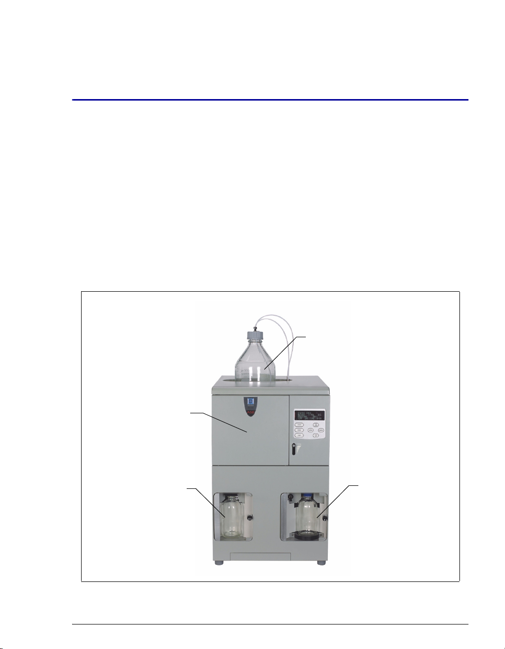
The ASE®150 Accelerated Solvent Extractor is a system for extracting either
organic or inorganic compounds from a variety of solid or semisolid samples at a
variety of pH values. The ASE 150 can be used with organic solvent, aqueous
buffer, water, and small amounts of mineral acids. The ASE 150 accelerates the
traditional extraction process by using solvent at elevated temperatures and
pressures. Pressure is maintained in the sample cell to maintain the heated solvent
in a liquid state during the extraction. After heating, the extract is rinsed from the
sample cell into a collection vessel and is ready for analysis.
Figure 1-1. ASE 150 Accelerated Solvent Extractor
Waste Collection Vessel
Solvent
Reservoir
Sample Cell
and Oven
Location

ASE 150 Operator’s Manual
2Doc. 065207-02 9/08
The ASE 150 is designed to minimize the amount of solvent used without
sacrificing the speed of extraction or ease of operation. Samples are extracted one
at a time, and the extraction process is typically completed in 15 to 25 minutes.
All functions are controlled from the ASE 150 front panel.
Built-in safety diagnostics monitor the system during operation. If a problem
occurs, the front panel displays an error message that identifies the problem. In
addition, the method currently running is aborted and basic system functions are
shut down until the situation is corrected.
1.2 About This Manual
1.2.1 Overview
The electronic version (i.e., PDF file) of the ASE 150 operator’s manual
contains numerous hypertext links that can take you to other locations
within the file. These links include:
•Table of contents entries
•Index entries
•Cross-references (underlined in blue) to sections, figures, tables, etc.
If you are not familiar with how to navigate PDF files, refer to the Help
system for Adobe® Acrobat® or Adobe Reader®for assistance.
Chapter 1
Introduction Introduces the ASE 150; explains the conventions used in
this manual, including safety-related information.
Chapter 2
Description Describes ASE 150 operating features and the extraction
process.
Chapter 3
Operation and
Maintenance
Provides operating instructions and routine preventive
maintenance procedures.
Chapter 4
Troubleshooting Lists error messages and how to troubleshoot them; lists
operating problems and how to resolve them.
Chapter 5
Service Provides step-by-step instructions for routine service and
parts replacement procedures that the user can perform.
Appendix A
Specifications Provides specifications and installation site requirements.

1 • Introduction
Doc. 065207-02 9/08 3
1.2.2 Safety Messages and Notes
This manual contains warnings and precautionary statements that can
prevent personal injury and/or damage to the ASE 150 when properly
followed. Safety messages appear in bold type and are accompanied by
icons, as shown below.
Messages d’avertissement en français
Appendix B
Installation Describes how to install the ASE 150.
Appendix C
User Interface Illustrates and describes the display screens on the ASE
150 front panel.
Appendix D
Reordering
Information
Lists spare parts for the ASE 150.
Appendix E
Theory of ASE Describes the theory behind performing extractions with
ASE.
Indicates an imminently hazardous situation which, if not avoided, will
result in death or serious injury.
Indicates a potentially hazardous situation which, if not avoided, may
result in death or serious injury.
Indicates a potentially hazardous situation which, if not avoided, may
result in minor or moderate injury. Also used to identify a situation or
practice that may seriously damage the instrument, but will not cause
injury.
Indicates that the function or process of the instrument may be
impaired. Operation does not constitute a hazard.
Signale une situation de danger immédiat qui, si elle n'est pas évitée,
entraînera des blessures graves à mortelles.

ASE 150 Operator’s Manual
4Doc. 065207-02 9/08
Warnhinweise in Deutsch
Notes
Informational messages also appear throughout this manual. These are
labeled NOTE and are in bold type.
NOTE NOTES call attention to certain information. They alert
the user to an unexpected result of an action, suggest
how to optimize instrument performance, etc.
Signale une situation de danger potentiel qui, si elle n'est pas évitée,
pourrait entraîner des blessures graves à mortelles.
Signale une situation de danger potentiel qui, si elle n'est pas évitée,
pourrait entraîner des blessures mineures à modérées. Également
utilisé pour signaler une situation ou une pratique qui pourrait
gravement endommager l'instrument mais qui n'entraînera pas de
blessures.
Bedeutet unmittelbare Gefahr. Mißachtung kann zum Tod oder
schwerwiegenden Verletzungen führen.
Bedeutet eine mögliche Gefährdung. Mißachtung kann zum Tod oder
schwerwiegenden Verletzungen führen.
Bedeutet eine mögliche Gefährdung. Mißachtung kann zu kleineren
oder mittelschweren Verletzungen führen. Wird auch verwendet, wenn
eine Situation zu schweren Schäden am Gerät führen kann, jedoch
keine Verletzungsgefahr besteht.

1 • Introduction
Doc. 065207-02 9/08 5
1.3 Safety and Regulatory Information
The ASE 150 was manufactured by Dionex Corporation at the following location:
527 Lakeside Drive, Sunnyvale, CA 94088-3603 U.S.A. The ASE 150 is designed
for solvent extraction applications and should not be used for any other purpose.
Operation of an ASE 150 in a manner not specified by Dionex may result in
personal injury.
If you have a question regarding appropriate usage, contact Dionex before
proceeding. In the U.S., call 1-800-346-6390 and select the Technical Support
option. Outside the U.S., call the nearest Dionex office.
1.4 Safety Labels
The cTUVus Mark safety label and the CE Mark label on the ASE 150 indicate
that the ASE 150 is in compliance with the following standards.
EMC Susceptibility and Emissions
•EN 61326-1:2006
Safety
•CAN/CSA-C22.2 No. 61010-1:2004
•EN 61010-1:2001
•UL 3101-1/10.93
•UL 61010-1:2004
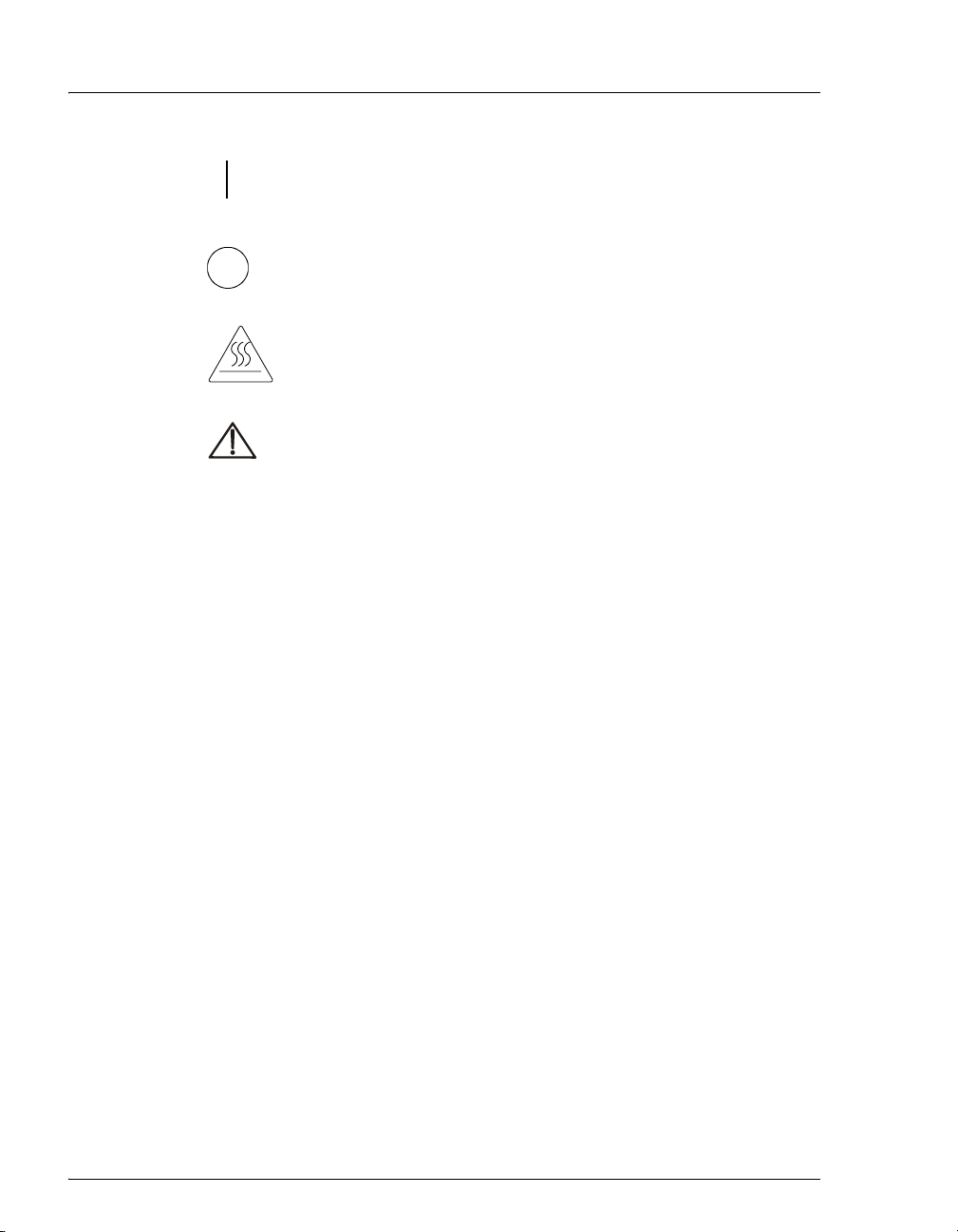
The symbols below appear on the ASE 150 or on ASE 150 labels.
Alternating current
Primary protective conductor terminal
Secondary protective conductor terminal
ASE 150 Operator’s Manual
6Doc. 065207-02 9/08
Power supply is on
Power supply is off
Hot surface
Indicates a potential hazard. Refer to the operator’s manual for
an explanation of the hazard and how to proceed.

Doc. 065207-02 9/08 7
2 • Description
2.1 Operating Features
Figure 2-1 illustrates the main operating features of the ASE 150 Accelerated
Solvent Extractor.
Figure 2-1. ASE 150 Operating Features
1Solvent Reservoir
Control Panel
2
Door OPEN Lever
4
5
6
3
1
2Oven
Sample Cell
Waste Bottle
Collection Vessel
(250-mL bottle shown)
Drip Tray
Needle UP/DOWN Switch
3
4
5
6
7
8
9
7
8
9

ASE 150 Operator’s Manual
8Doc. 065207-02 9/08
Solvent Reservoir
A 2-liter solvent reservoir is installed in a recess on top of the ASE 150. The
recess contains a plastic liner that collects any solvent leaks or spills that may
occur and directs them through a drain tube to the rear panel. A drain hose
connects to the drain tube and is routed to a waste container.
Sample Cell
Before a sample is run or a rinse cycle is performed, a sample cell or rinse cell
must be installed in the cell holder on the inside of the cell door. To access the cell
holder, push down on the OPEN lever and then pull open the door.
Oven
The oven is located behind the cell door. This area also houses the AutoSeal™
tips, which seal the cell during a run.
Control Panel
The ASE 150 control panel includes a display screen and a membrane keypad,
which are used to control ASE 150 operation.
Waste Bottle
The waste bottle is a 250-mL collection bottle that is sealed with a special built-in
cap assembly.
Needle Up/Down Switch
The UP/DOWN toggle switch controls the position of the source and vent needles.
When the needles are in the “down” position, they pierce the collection vessel
septum. The source needle allows the extract to flow from the sample cell into the
collection vessel. The vent needles allow displaced gases to escape to the waste
bottle and the system vent.
Drip Tray
A pull-out drip tray is installed below the oven to collect any liquid leaks that may
occur during a run or rinse cycle.
Collection Vessel
After each extraction, the collection vessel (either a 250-mL collection bottle or a
60-mL collection vial) contains solvent and the analytes extracted from the
sample.
2 • Description
Doc. 065207-02 9/08 9
Safety Shields
The doors on the waste and collection vessel compartments are safety shields that
protect operators in the rare case of a bottle or vial breakage. The doors must be
closed for safe operation.
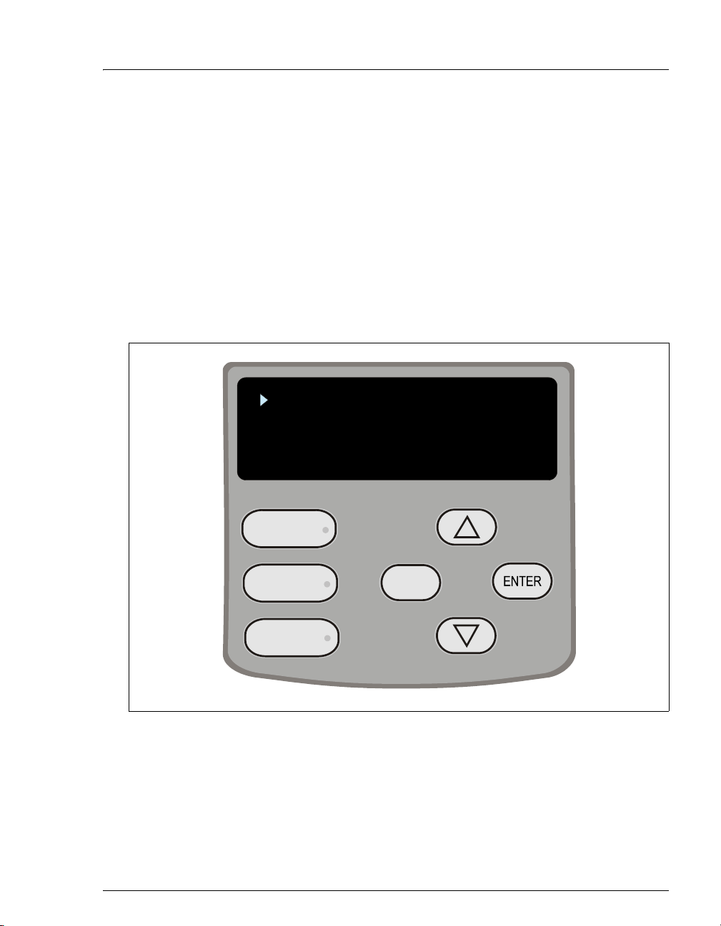
2.1.1 Control Panel
Use the control panel screen and buttons to control ASE 150 operation.
The screen displays status and operating information. You can edit any
field on the screen that contains a blinking cursor. A field without a
blinking cursor is for display only.
Figure 2-2. ASE 150 Control Panel
STATUS
SETUP
METHOD EDITOR
DIAGNOSTICS
START
RINSE
STOP
MENU

ASE 150 Operator’s Manual
10 Doc. 065207-02 9/08
Button Function
Starts the currently selected method. The LED starts flashing
when the oven is within 1 °C of the set point, indicating it is
okay to load the sample cell into the oven. During the method
run, the LED is lighted, but does not flash. When the method
finishes running (or is aborted), three beeps are emitted and
the LED turns off. See Section 2.4 for details about methods.
Starts a rinse cycle in which about 5 mL of solvent is pumped
through the system. During the rinse cycle, the LED is
lighted. When the rinse cycle is complete (or is aborted),
three beeps are emitted and the LED turns off.
Note: Always install a rinse cell and a collection vessel
before starting a rinse cycle. See Section 3.5 for instructions.
Interrupts the currently running method or rinse cycle and
displays the ABORT screen. Pressing the button lights the
LED. The LED turns off when you select an option on the
ABORT screen. See Section 3.4 for details.
Exits the screen currently displayed and returns to the screen
one level up in the hierarchy. For example, if the METHOD
EDITOR screen is displayed, pressing MENU returns you to
the MENU screen. See Figure C-1 for an overview of the
screens.
When the cursor is in an editable field, pressing MENU
discards any change and reverts to the previously selected
parameter.
Selects the field the cursor is currently pointing to. On the
MENU or DIAGNOSTICS screen, this selects and displays a
different screen. On other screens, pressing ENTER moves
the cursor from the left margin to the first field in that line
that can be edited; it also changes the normal cursor into the
blinking editing cursor.
When the cursor is in an editable field, pressing ENTER saves
the parameter currently displayed in the field.
Table 2-1. ASE 150 Control Panel Button Functions
START
RINSE
STOP
MENU
2 • Description
Doc. 065207-02 9/08 11
2.1.2 Sample Cells and Rinse Cells
NOTE Appendix D contains part numbers for cells, bottles,
vials, and other accessories.
Sample Cells
Sample cells consist of a cell body and two interchangeable caps, which
are screwed onto each end of the cell body. The cell body and end caps
are made of the same material. Inside each end cap is a frit in the same
material as the cell, as well as a PEEK™ seal. During a run, the cell end
caps are compressed by the oven to form a tight seal between the caps and
the cell body.
Each cell end cap contains an external O-ring. Teflon® O-rings
(P/N 049457, pkg. of 50) are standard. Use Viton® O-rings (P/N 056325,
pkg. of 50) for dioxins and other high temperature applications.
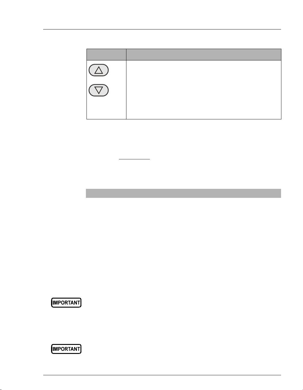
Moves the cursor, in the direction of the arrow, to the next
selectable line on the display (if any).
When the cursor is in an editable field, pressing an arrow
button displays the next or previous parameter or numeric
value allowed for the field.
Note: Pressing and holding down an arrow button moves the
cursor continuously through the allowed settings.
Cell Material Sizes Available (mL) Used For
Stainless steel 1, 5, 10, 22, 34, 66, and
100
Extractions with solvents
Zirconium 66 and 100 Extraction of basic or acidic
matrices, and extractions with
solvents
Always tighten the cell end caps by hand. Use of a wrench or other
tool can damage the cell, as well as the seals inside the cell end caps.
If Viton external O-rings are installed on the cell end caps, do not use
acetone or other ketones.
Button Function
Table 2-1. ASE 150 Control Panel Button Functions (Continued)

ASE 150 Operator’s Manual
12 Doc. 065207-02 9/08
Rinse Cells
Rinse cells are similar in appearance to sample cells, but are blue in color.
During a rinse cycle, solvent passes directly through the rinse cell and
into the collection vessel. For more information about rinse cycles, see
Section 3.5.
The rinse cell size must be matched to the size of the sample cell, as
indicated in the table below.
Ordering Sample Cells in Other Sizes
To perform a run with a cell in a different size than the size originally
ordered, order the cells from Dionex. You will also need to order the
Startup Kit appropriate for the new cell size. For cell and Startup Kit part
numbers, see Appendix D.
Note that installation of a different sample cell size will require a few
additional changes:
•Reposition the cell holder to accommodate the new sample cell size,
if required. For instructions, refer to Section B.2.8.
•Before beginning a run, specify the new cell size on the SETUP screen
(see Section C.1.3).
Use this rinse cell: With this sample cell:
Short (P/N 060174) 1 mL, 5 mL, 10 mL, 22 mL, 34 mL
Medium (P/N 060175) 66 mL
Long (P/N 060176) 100 mL
Table of contents
Popular Scrubber manuals by other brands

Sana
Sana EUJ-702 user manual

HAKO
HAKO Scrubmaster B400 R operating manual

Black & Decker
Black & Decker S500 instruction manual

Lincoln Electric
Lincoln Electric LFA 3.0 Installation and user manual

SapphireScientific
SapphireScientific Dri-Eaz HVE3000 owner's manual

Nilfisk-Advance
Nilfisk-Advance Adfinity 20D Instructions for use


