1. General information
The chapter Operation is intended for the user and the heating
contractor.
The chapter Installation is intended for the heating contractor.
Please read carefully.
Read these instructions carefully before using this
appliance and retain for future reference. If the
appliance is passed on to a third party please hand
these instructions to the new user.
1.1 Key
1.1.1 Symbols in these installation instructions:
In this documentation you will come across symbols and highlights
that are defined as follows:
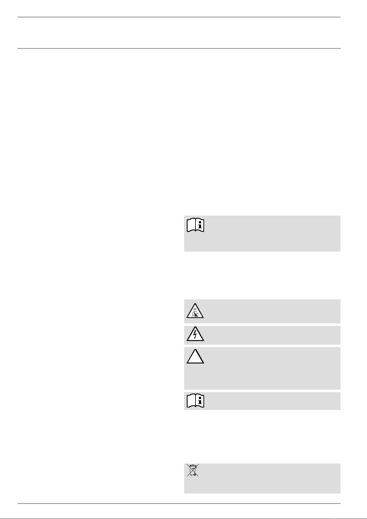
Risk of injury!
Information regarding possible risks of injury for
installer or users and potential equipment damage.
Danger to life through electrocution!
! Risk of damage!
Information regarding potential situations that
bring a risk with them that might occur during
the appliance installation or opearation, the
consequences of which may be equipment damage,
environmental pollution or material loss.
Please read carefully.
Read this section carefully.
»Passages with this symbol "»" indicate step-by-step procedures
you must carry out.
—Passages with this symbol "–" indicate lists.
1.1.2 Symbols on the appliance
This symbol is defined as follows:
Appliance disposal
Appliances with this marking are not suitable for
general waste disposal, and should therefore be
disposed of separately.
OPERATION ____________________________________________ 16
1. General information ������������������������������������������ 16
1.1 Key ��������������������������������������������������������������������16
2. Safety ���������������������������������������������������������� 17
2.1 Correct use ���������������������������������������������������������� 17
2.2 Safety instructions ������������������������������������������������ 17
2.3 CE designation ����������������������������������������������������� 17
3. Device description �������������������������������������������� 17
3.1 Properties ____________________________________________________ 17
3.2 Functions and properties ���������������������������������������� 17
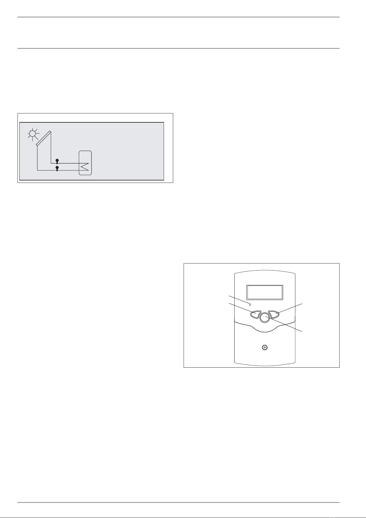
4. Operation ������������������������������������������������������ 18
4.1 Graphic display ���������������������������������������������������� 18
4.2 Control levels �������������������������������������������������������18
4.3 Operation with keys ����������������������������������������������� 18
5. Settings and prompts ��������������������������������������� 19
6. Display and adjustable parameters ������������������������ 19
6.1 Display parameters ����������������������������������������������� 19
6.2 Adjustable parameters ������������������������������������������� 19
6.3 Heat volume �������������������������������������������������������� 19
6.4 Flow and return temperatures ���������������������������������� 19
6.5 Flow rate ������������������������������������������������������������ 19
6.6 Output ��������������������������������������������������������������� 20
6.7 Frost protection ���������������������������������������������������� 20
6.8 Pulse value ����������������������������������������������������������20
6.9 Subaddress ��������������������������������������������������������� 21
6.10 BUS mode ����������������������������������������������������������� 21
6.11 BUS master ��������������������������������������������������������� 21
6.12 Sensor balancing �������������������������������������������������� 21
6.13 Reset �����������������������������������������������������������������22
6.14 Language ������������������������������������������������������������ 22
7. What to do if... ������������������������������������������������ 22
7.1 LED flashing codes at the heat meter �������������������������� 22
7.2 Fuses ����������������������������������������������������������������� 22
INSTALLATION _________________________________________ 23
8. Safety ���������������������������������������������������������� 23
8.1 Country-specific safety information ��������������������������� 23
8.2 Instructions, standards and regulations ���������������������� 23
9. Device description �������������������������������������������� 23
9.1 Properties ����������������������������������������������������������� 23
9.2 Standard delivery: ������������������������������������������������� 23
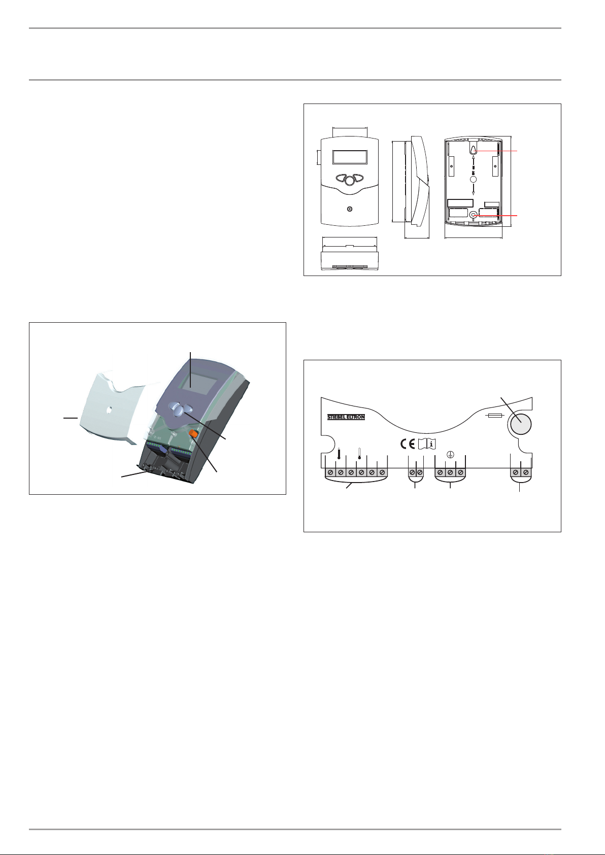
10. Installation location ������������������������������������������ 24
10.1 Assembly ������������������������������������������������������������ 24
10.2 Fixing ����������������������������������������������������������������24
10.3 Electrical connection ���������������������������������������������� 24
10.4 Hydraulic connection of the meter ����������������������������� 25
11. Operation with a controller ��������������������������������� 25
11.1 Conversion from master to slave ������������������������������� 25
11.2 PCB relacement ���������������������������������������������������� 26
12. Connection examples ���������������������������������������� 26
12.1 Standalone operation ��������������������������������������������� 26
12.2 Operation with control unit�������������������������������������� 26
12.3 Cascade without control unit ������������������������������������ 27
12.4 Cascade with control unit ���������������������������������������� 27
13. Specification ��������������������������������������������������� 27
13.1 Dimensioned drawing �������������������������������������������� 27
13.2 Specification �������������������������������������������������������� 27
CUSTOMER SERVICE AND WARRANTY _______________ 28
ENVIRONMENT AND RECYCLING ______________________ 29
285309-36390-8670_SOM-WMZ-SOL_de_en_fr_nl_sv.indb 16 08.11.2011 09:27:58