PAT America DS 350 User manual

ww.patamerica.com PAT America, Inc.
LOAD MOMENT INDICATOR
DS 350 MODULAR/GRAPHIC
for Lattice Boom Cranes
SERVICE MANUAL
P/N 031-300-190-118 REV. -, 12/18/2000


Service Manual DS 350 Modular
© PAT Rev. – 12/18/00 // CSH. 190118_-.DOC
NOTICE
The information in this document is subject to change without notice.
PAT makes no warranty of any kind with regard to this material, including, but not limited to the implied warranties
of merchantability and fitness for a particular purpose.
PAT shall not be liable for errors contained in this manual or for incidental or consequential damages in
connection with the furnishing, performance, or use of this manual. This document contains proprietary
information, which is protected by copyright. All rights are reserved.
No part of this document may be photocopied, reproduced, or translated to another language without the prior
written consent of PAT.
MANUAL REVISIONS
REV DATE NAME DESCRIPTION
- 12/18/00 CSH Troubleshooting Manual created.
© 2000 PAT America, Chambersburg, PA 17201, USA


Service Manual DS 350 Modular
© PAT Rev. - 12/18/00 // CSH. 190118_-.DOC
TABLE OF CONTENTS
1GENERAL INFORMATION................................................................................................1
2WARNINGS .......................................................................................................................1
3SYSTEM DESCRIPTION...................................................................................................2
4GENERAL FLOW CHARTS...............................................................................................3
5ERROR CODES.................................................................................................................4
5.1 OPERATING ERRORS E01 THROUGH E06......................................................................................4
5.2 LOCKOUT FUNCTION ERRORS 07 AND 08......................................................................................5
5.3 ANALOG INPUT CHANNEL ERRORS................................................................................................5
5.4 ERRORS 31 AND UP.....................................................................................................................6
6FUNCTION LOCKOUT ....................................................................................................10
7NO DISPLAY....................................................................................................................11
8ANTI-TWO BLOCK PROBLEM........................................................................................13
9ANGLE SENSORS...........................................................................................................16
10LOAD READING..............................................................................................................18
11AREA DEFINITION INDICATION PROBLEM..................................................................20
12DATA TRANSFER CENTRAL UNIT <--> CONSOLE ......................................................21
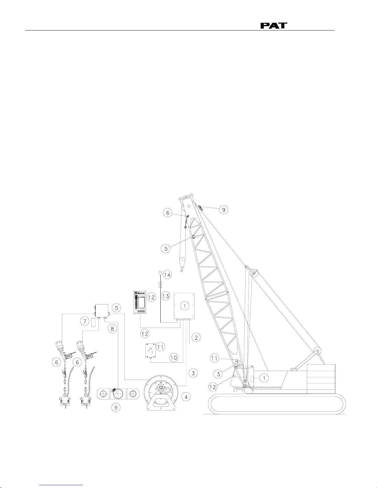
13DRAWINGS .....................................................................................................................23
13.1 ELECTRICAL WIRING (DRAWING 1) PART 1................................................................................23
13.2 CENTRAL UNIT BREAKDOWN / PARTS LIST (DRAWING 2)............................................................25
13.3 CONSOLE DS350/1334 / PARTS LIST (DRAWING 3)...................................................................27
13.4 CENTRAL UNIT MAIN BOARD LAYOUT (DRAWING 4) ...................................................................28
13.5 CENTRAL UNIT ANALOG INPUT MODULE (DRAWING 5)................................................................29
13.6 CONSOLE CONNECTION BOARD (DRAWING 6) ...........................................................................30
13.7 FORCE TRANSDUCER (DRAWING 7)..........................................................................................31
13.8 AREA DEFINITION SWITCH (DRAWING 8) ...................................................................................31
13.9 BOOM JUNCTION BOX (DRAWING 9)..........................................................................................32
13.10 CABLE REEL (DRAWING 10)...................................................................................................33
14PROCEDURES................................................................................................................34
14.1 PROCEDURE 1: EPROM LOCATION AND INSTALLATION..............................................................34
14.2 PROCEDURE 2: MAIN BOARD REPLACEMENT.............................................................................35
14.3 PROCEDURE 3: ANGLE SENSOR ADJUSTMENT/REPLACEMENT....................................................36
14.4 TROUBLESHOOTING MOISTURE.................................................................................................37
14.5 THEORY 1: OPERATION OF ANGLE SENSOR...............................................................................39


General Information
© PAT Rev. - 12/18/00 // CSH. 190118_-.DOC
1
1 GENERAL INFORMATION
The PAT Load Moment Indicator (LMI) DS 350 has been designed to provide the crane operator with the
essential information required to operate the machine within its design parameters.
Using different sensing devices, the Load Moment Indicator monitors various crane functions and provides the
operator with a continuous reading of the crane’s capacity. The readings continuously change as the crane
moves through the motions needed to make the lift.
The LMI provides the operator with information regarding the angle of the boom, working radius, rated load and
the total calculated weight being lifted by the crane.
If non permitted conditions are approached, the DS 350 Load Moment Indicator will warn the operator by
sounding an audible alarm, lighting a warning light and locking out those functions that may aggravate the crane’s
condition.
Refer to operator’s manual 031-300-190-089 for console operating instructions.
2 WARNINGS
The LMI is an operational aid that warns a crane operator of approaching overload conditions and of over hoist
conditions that could cause damage to equipment and personnel.
The device is not, and shall not, be a substitute for good operator judgment, experience and use of accepted safe
crane operating procedures.
The responsibility for the safe crane operation shall remain with the crane operator who shall ensure that all
warnings and instructions supplied are fully understood and observed.
Prior to operating the crane, the operator must carefully and thoroughly read and understand the information in
this manual to ensure that he knows the operation and limitations of indicator and crane.
Proper functioning depends upon proper daily inspection and observance of the operating instructions set forth in
this manual. Refer to Section Pre-Operation Inspection and Calibration Verification of the operator’s manual.
The LMI can only work correctly, if all adjustments have been properly set. For correct adjustment, the
operator has to answer thoroughly and correctly all questions asked during the setup procedure in
accordance with the real rigging state of the crane. To prevent material damage and serious or even
fatal accidents, the correct adjustment of the LMI has to be ensured before starting the crane
operation.

Service Manual DS 350 Modular
© PAT Rev. - 12/18/00 // CSH. 190118_-.DOC
2
3 SYSTEM DESCRIPTION
The PAT Load Moment Indicator DS 350 consists of a central microprocessor unit, operating console, angle
sensor, force transducer, and anti-two block switches.
The system operates on the principle of reference/real comparison. The real value, resulting from the load
measurement is compared with the reference data, stored in the central processor memory and evaluated in the
microprocessor. When limits are reached, an overload warning signal is generated at the operator’s console. At
the same time, the aggravating crane movements, such as hoist up and boom down, will be stopped.
The fixed data regarding the crane, such as capacity charts, boom weights, centers of gravity and dimensions are
stored in memory chips in the central processor unit. This data is the reference information used to calculate the
operating conditions.
The boom angle is measured by the angle sensor, mounted in the boom base. The cable reel cable serves as an
electrical conductor for the anti two-block switches and force transducer signals.
The load on the boom is measured by force transducer mounted on top of the boom, close to the tip.
The interactive user guidance considerably simplifies the input of operating modes as well as the setting of
geometry limit values. Please refer to the PAT DS350 operator’s manual for the operation of the system.
The System consists of the following main components:
1. Central Unit
2. Cable for crane power
3. Cable to cable reel
4. Cable Reel
5. Junction box
6. A2B switch with weight
7. A2B bypass plug
8. Cable to force transducer
9. Force transducer
10. Cable to main boom angle sensor
11. Main boom angle sensor
12. Operator’s console with cable assembly
13. Cable for area definition sensor
14. Area definition sensor
Fig. 1: Components of the LMI system PAT DS 350/Modular

General Flow Charts
© PAT Rev. - 12/18/00 // CSH. 190118_-.DOC
3
4 GENERAL FLOW CHARTS
This section explains how to handle a problem that may arise with the PAT DS 350 Modular System.
The procedures are given in flowchart format for the following sections. Start with the general
flowchart below that will guide you to one of the detailed flowcharts shown in Sections 5 through 12.
The drawings and procedures that are referenced in these sections can be found in Section 13 and
14.
What’s Wrong?
Lever Lockout Activated Go to Section 6
No display
Anti-Two Block Problem
Load Reading Problem
Bad Data Transfer/Interference
Between Central Unit and Console
Area Definition Indication Problem
Go to Section 7
Go to Section 8
Go to Section 9
Go to Section 10
Go to Section 12
Angle Reading Problem
Go to Section 11
Error Code Displayed Go to Section 5

Service Manual DS 350 Modular
© PAT Rev. - 12/18/00 // CSH. 190118_-.DOC
4
5 ERROR CODES
5.1 Operating Errors E01 through E06
These errors are usually caused by operating in a way that is not allowed per the load charts.
Error Code Error Cause Elimination
E01 Fallen below
radius range or
angle range
exceeded
• Fallen below the minimum
radius or gone past the
maximum angle specified in the
respective load chart due to
hoisting up the boom too far
• Hoist the boom down to a
radius or angle specified
in the load chart.
E02 Radius range
exceeded or
fallen below
angle range
• Gone past the maximum radius
or fallen below the minimum
angle specified in the respective
load chart due to hoisting down
the boom too far
• Hoist the boom up to a
radius or angle specified
in the load chart.
E04
Operating
mode not
existing or non
permitted
slewing zone
• A non existing operating mode
has been selected
• Set the correct operating
mode for the crane
configuration in question
• The selected operating mode is
not available in the data
EPROM or blocked.
• Check programming of the
data EPROM
• The boom is in a non-permitted
slewing zone • Slew the crane into a
permitted area.
E05
Boom length
not existing
• A non existing boom length has
been selected
• Correctly enter the boom
length according to the
attribution of the
operating state
• The selected boom length is not
available in the data EPROM. • Check programming of
the data EPROM
E06 Radius range
exceeded or
fallen below
angle range
with luffing jib
operation
• Maximum radius as specified in
the load chart exceeded or
fallen below minimum angle due
to luffing down the luffing jib too
far
• Luff the jib to a radius or
angle specified in the load
chart.

Error Codes
© PAT Rev. - 12/18/00 // CSH. 190118_-.DOC
5
5.2 Lockout Function Errors 07 and 08
These errors are caused by defects around the function lockouts.
Error
Code Error Cause Elimination
E07 Faulty acknowledgment
of the overload relay on
the connection board.
The relay should be
energized, the 2nd
contact however is
indicated to be off, or the
2nd contact is indicated to
be on while the relay
should be de-energized.
• Overload relay or main
board are defective
• Processor board
defective
• Replace main board
• Replace processor board.
E08 No acknowledgment from
the anti-two-block relay • refer to E07 • refer to E07
5.3 Analog Input Channel Errors
These errors occur if the input signal of an analog input channel falls below (E1x) the minimum (4 mA)
or exceeds (E2x) the maximum (20 mA).
The analog channels are used as follows:
Sensor Pins Terminal X1 Lower Limit Upper Limit
Main Force Transducer 36 E14 E24
Angle Sensor (Main Boom) 29 E15 E25
Each channel is constantly being monitored to be within 4 mA (1.1V resp.) and 20 mA (5.5V resp.). If
it exceeds these limits, the following errors are triggered:
Error Code Error Cause Elimination
E14
Fallen below the
lower limit value in
the main force
channel
• Cable between the central
unit and force transducer
defective or water inside the
plugs
• Check cable as well as
plugs, replace, if need be.
• Force transducer is
defective. • Replace force transducer
• Electronic component in the
measuring channel is
defective.
• Replace LMI module(s).
E24 Upper limit value in
main force
transducer
measuring channel
has been exceeded
• refer to E14
• refer to E14
E15 Fallen below lower
limit value in
measuring channel
"angle main boom"
• Cable between central unit
and the angle sensor
defective or loose. Water
inside the plugs.
• Check cable as well as
plugs, replace, if need be.
• Angle sensor defective • Replace angle sensor

Service Manual DS 350 Modular
© PAT Rev. - 12/18/00 // CSH. 190118_-.DOC
6
Error Code Error Cause Elimination
• Electronic component in the
measuring channel
defective.
• Replace LMI module(s).
E25
Upper limit value in
measuring channel
"main boom angle"
has been exceeded.
• refer to E15 • refer to E15
E19
Reference and/or
supply voltage
defective
• The supply voltage is being
dragged down by one of the
sensors
• Check the voltages on the
LMI main board (AGND =
MP0). Check sensors,
plugs and cable, replace, if
need be.
• Electronic component is
defective • Replace LMI main board
• A/D converter defective. • Replace analog board
E29 Reference and/or
supply voltage
defective.
• refer to E19
• refer to E19
5.4 Errors 31 and up
Miscellaneous Errors, most of them caused by electronics.
Error Code Error Cause Elimination
E31
Error in the system
program • The system program PROM is
defective. • Replace system program
PROM (PROM No. 0)
E38
System program
and data EPROM
do not match.
• The system program in the LMI
does not match to the
programming in the data
EPROM
• Replace the system
program PROM or the
data EPROM (PROM No.
1)
E41
Error in the internal
write/read memory
(RAM) of the
computer
component 80C537
• Computer component 80C537
defective
• CPU module defective
• Processor board defective.
• Replace computer
component 80C537.
• Replace CPU module.
• Replace processor board
with CPU module.
E42
Error in the external
write/read memory,
1st part (RAM)
• Write/read memory (CMOS
RAM) or processor board
defective.
• Replace processor board
with CPU module.
E43 Error in the external
write/read memory,
2nd part (RAM)
• refer to E42 • refer to E42
E45
Redundancy error
in the A/D
conversion
• The A/D converter on the
processing board and the
redundant A/D converter in the
CPU 80C537 provide different
results.
• Replace processor board.
E46
Error in the A/D
converter uPD 7004
of the processor
board.
• No acknowledgment of the A/D
converter uPD 7004 • Replace processor board.

Error Codes
© PAT Rev. - 12/18/00 // CSH. 190118_-.DOC
7
Error Code Error Cause Elimination
E47 Error in the
monitored write/
read memory.
The CRC
verification of the
monitored
write/read memory
provides an
incoherent result
• The CRC sign of the monitored
write/read memory is wrong
• The buffer battery is discharged
(< 2V at 1kOhm).
• Processor board defective.
• Restart the LMI
• Replace buffer battery on
the LMI main board
• Replace processor board.
E48
Cyclic RAM test:
error in the internal
write/read memory
(RAM) of the
computer
component 80C537
• Computer component 80C537
defective
• CPU module defective
• Processor board defective.
• Replace computer
component 80C537.
• Replace CPU module
• Replace processor board
with CPU module.
E51
Error in the data
EPROM or
EEPROM.
• No valid data in the data
EEPROM.
• Memory module wrongly
bridged.
• Crane data EPROM defective
• Load data EEPROM
containing valid data.
• Bridge memory module
acc. to memory type
• Replace crane data
EPROM
E56
Error in the data
EEPROM.
• Memory module wrongly
bridged.
• Crane data EEPROM defective
• Bridge memory module
acc. to memory type
• Replace crane data
EEPROM
E57
Error in serial crane
data EEPROM. • Serial crane data EEPROM
does not contain valid data.
• Memory module defective
• Write data on the serial
crane data EEPROM (by
means of test program or
on-line function), then
restart the LMI
• Replace memory module.
E58
Error in the serial
analog data
EEPROM.
• No valid data in the serial
analog data EEPROM.
• LMI module(s) defective.
• Write data on the serial
analog data EEPROM by
means of the test
program, then, restart the
LMI
• Replace LMI module(s).
E60 The number of the
selected EPROM • Load chart EPROM defective • Replace load chart
EPROM
base and the
programmed value
are not identical
• Base number not programmed • Program the correct base
number (1 for base 1, 2
for base 2)
• Load chart EPROM wrongly
programmed • Check base programming
in the load chart EPROM.
E71 Faulty
acknowledgment of
relay K1 on the
connection board
• Relay K1 or main board
defective. • Replace main board.

Service Manual DS 350 Modular
© PAT Rev. - 12/18/00 // CSH. 190118_-.DOC
8
Error Code Error Cause Elimination
Relay should be
energized but the
2nd contact is
signaled to be off or
the 2nd contact is
signaled to be on
whereas the relay
should be de-
energized.
• Main board is defective
• Replace main board.
E72
...
E77
Faulty
acknowledgment of
relays K2...K7 on
the connection
board.
• refer to E71
• refer to E71
E91 No data trans-
mission form the
console to the
• 24 V supply of the console is
interrupted • Check 24 V at terminal
X1 of the console
electronics
central unit • Interruption or accidental
ground in the line between
console electronics and central
unit
• Check the connection
console electronics -
central unit. In case of an
accidental ground, the
transmitter module of the
console electronics might
be damaged. Therefore,
replaces the console
electronics.
• Transmitter/receiver module is
defective • Exchange console
electronics or LMI main
board resp.
E92 Error in the data
transmission from
console to central
unit
• Loose connection in the line
between console electronics
and central unit
• Transmitter/receiver module is
defective
• Check the connection
between console
electronics and central
unit
• Exchange console
electronics or LMI main
board resp.
E93 Error in the data
transmission from
the central unit to
the console
• refer to E92 • refer to E92
E94
No data trans-
mission from the
central unit to the
console
• Interruption or accidental
ground in the cable between
central unit and console
• Check wiring to the
console (in case of
accidental ground,
replace console
electronics, too).
• 5 V supply of the computer in
the central unit is missing • Check connection to the
power unit
• 5 V supply is too low • Exchange the LMI main
board

Error Codes
© PAT Rev. - 12/18/00 // CSH. 190118_-.DOC
9
Error Code Error Cause Elimination
• Transmitter/receiver module is
defective • Replace console
electronics or LMI main
board
• Computer module is defective • Replace processor board.
• Electro-magnetic interferences
(e.g. when switching contactors
or valves)
• Eliminate the source of
interferences by inverse
diodes or varistors.
E95
Error in the console
EPROM • The console EPROM is
defective. • Replace the console
EPROM
E96
Error in the internal
RAM of the console.
• The CPU of the console is
defective.
• The console main board is
defective.
• Replace the CPU of the
console
• Replace the console main
board.
E97
Error in the external
RAM of the console • The external RAM of the
console is defective.
• The console main board is
defective.
• Replace the external
RAM of the console.
• Replace the console main
board.
EAB Short circuit in the
A2B switch circuit • Short circuit in the A2B switch
• Short circuit in the cable to the
A2B switch
• Replace A2B switch
• Replace cable to the A2B
switch
Note:
If an error message is displayed which is not contained in above list, please contact the PAT
service department.

Service Manual DS 350 Modular
© PAT Rev. - 12/18/00 // CSH. 190118_-.DOC
10
6 FUNCTION LOCKOUT
Fault in crane electric, hydraulic system, or
electronic board.
PROBLEM: The lever lockout system of the crane is activated. Crane movements “hoist up” and (optional)
“boom down” are stopped. Only if the crane is not in overload or two-block condition continue with flow chart.
WARNING: If overload or A2B condition exists, use extreme caution and move the crane out of the
condition.
If Error Code is displayed goto Section 5.
Corrected
Check lever lockout
system in crane
service manual.
Relay defective on the main
board. Replace main board.
Refer to Sect. 14, Procedure 2.
Main board replacement.
The LMI by-pass warning light and/or anti-two-block
warning light is lit on the console.
LED's H8, H9, and H10 are lit on the main/terminal board.
Refer to Drawing 4 in Section 13.
The fault is located in LMI, cables,
wiring, fuses, or console.
Read error code displayed on
console and go to Section 5.
Start
Use the console key switch and the LMI by-pass button or the central unit key switch to override the overload.
When by-passing the system, the following instructions must be obeyed:
!The by-pass function shall be used with discretion, as unwarranted use of it to override the control lever
lockout system can result in harm to the crane and danger to property and persons.
!Never use the by-pass function to either overload or operate the crane in a non-permissible range.
YES
NO

Anti-Two Block
© PAT Rev. - 12/18/00 // CSH. 190118_-.DOC
11
7 NO DISPLAY
PROBLEM: Blank console display with no warning light shown. All crane moments have
been stopped.
Measure voltage on the main board terminal strip between X1:1 (+12/24V) and X1:2
(ground). This is an input voltage from the crane.
Refer to Drawing 1.
Check fuses in central unit.
Replace fuses.
Measure voltage on the main board between X1:3 (+12/24V) and X1:4 (ground).
This is an output voltage to the console.
Refer to Drawing 1.
NEXT PAGE
START
NO
Check crane power supply for faulty
wiring in crane electric.
NO
YES
YES
NO
Replace the main board in central unit.
Refer to Drawing 2 and Replacement
Procedure 2.
YES
Corrected
Corrected
Corrected

Service Manual DS 350 Modular
© PAT Rev. - 12/18/00 // CSH. 190118_-.DOC
12
Console/Display is defective. Replace the console.
Refer to Drawing 1 and 3.
Check connections of the cable between
console and central unit. Replace cable if
necessary. Refer to Drawing 1 in Section 13.
END
Correct?
PREVIOUS PAGE
NO
Measure voltage in the console between X1:1 (+12/24V) and X1:2 (ground).
Refer to Drawing 1, 3, & 6.
YES

Anti-Two Block
© PAT Rev. - 12/18/00 // CSH. 190118_-.DOC
13
8 ANTI-TWO BLOCK PROBLEM
Check by-pass plugs installed and system cables connected.
Refer to Drawing 1 and 2.
PROBLEM: Function of Anti-Two-Block System is faulty.
START
Check to see whether or not crane is in two-block condition.
Correct? Lower hook down into safe position
Plug appropriate bypass plug or system cable
connectors into socket.
Refer to Drawing 1 and 2.
Next Page
Correct?
NO
NO
YES
YES
Check anti-two block weight and/or flags whether installed correctly.
Refer to Operator's Manual: Pre-Operational Inspection and Calibration.
Install A2B weight or flag, if not correctly
installed.
Correct?
NO
YES

Service Manual DS 350 Modular
© PAT Rev. - 12/18/00 // CSH. 190118_-.DOC
14
PREVIOUS PAGE
Measure voltage on the main board terminal strip between X1:31 (+9V±0.5) and
X1:2(ground). This is an input voltage from the system.
Refer to Drawing 1 and 4.
Correct? Replace the main board in central unit.
Refer to Drawing 2 and Replacement Procedure 2.
NO
YES
The A2B circuit supplies 9 volts to the circuit and a 4.7K resistor in the circuit modifies the return signal to
4.5 volts. The computer continuously monitors this signal to ensure the signal is between for a 3 to 6
volt, if the signal is:
!
less than 3 (open) A2B alarm and light. Check wiring for open circuit - switch not connected,
bypass plugs not installed, or sensor cables not connected
!
greater than 6 (short) then EAB error is given to the system. The signal is returned to the CU
unmodified; for example, a jumper wire connected between X1:31 and X1:32 in CU.
If the signal is within 3 to 6 volts or the A2B circuit is by-passed; LED H9 on the main board will be lit.
Refer to Drawing 3.
Measure voltage on the main board terminal strip between X1:31 (+9V±0.5) and
X1:32(A2B GND). This is the voltage in the A2B circuit. <3 open and >6 short in system
Refer to Drawing 1 and 4.
>6 volts<3 volts
!
Look for damaged cable between central unit and boom tip
junction box.
!
Check 4.7K resistor in boom tip junction box. Turn system power
off and measure resistance between terminal 5 in junction box and
pin A of 7 socket receptacle. measurement reading = 4.7K .
!
check for short between terminals 5 and 6 in boom tip junction box
or between X1:31 and X1:32 in CU.
YES
YES
NEXT PAGE
Other manuals for DS 350
2
Table of contents
Other PAT America Touch Panel manuals