Boonton CPS2000 User manual
CPS2000
True-Average Connected Power Sensors
INSTRUCTION MANUAL
98408200A | Rev 0

CPS2000 Series Instruction Manual
SAFETY SUMMARY
The following general safety precautions must be observed during all phases of operation and
maintenance of this instrument. Failure to comply with these precautions or with specific warnings
elsewhere in this manual violates safety standards of design, manufacture, and intended use of the
instrument. Boonton Electronics assumes no liability for the customer’s failure to comply with these
requirements.
DO NOT OPERATE THE INSTRUMENT IN AN EXPLOSIVE ATMOSPHERE
Do not operate the instrument in the presence of flammable gases or fumes.
KEEP AWAY FROM LIVE CIRCUITS
Operating personnel must not remove instrument covers. Component replacement and internal
adjustments must be made by qualified maintenance personnel. Do not replace components with the
power cable connected. Under certain conditions dangerous voltages may exist even though the power
cable was removed, therefore; always disconnect power and discharge circuits before touching them.
DO NOT SERVICE OR ADJUST ALONE
Do not attempt internal service or adjustment unless another person, capable of rendering first aid and
resuscitation, is present.
DO NOT SUBSTITUTE PARTS OR MODIFY INSTRUMENT
Do not install substitute parts or perform any unauthorized modifications on the instrument. Return the
instrument to Boonton Electronics for repair to ensure that the safety features aremaintained.
S-1 SAFETY SUMMARY Page 2

CPS2000 Series Instruction Manual
SAFETY SYMBOLS
This safety requirement symbol has been adopted by the International Electro-technical
Commission, Document 66 (Central Office) 3, Paragraph 5.3, which directs that an
instrument be so labeled if, for the correct use of the instrument, it is necessary to refer to
the instruction manual. In this case it is recommended that reference be made to the
instruction manual when connecting the instrument to the signal source and USB host.
The CAUTION symbol denotes a hazard. It calls attention to an operational procedure,
practice or instruction that, if not followed, could result in damage to or destruction of
part or all of the instrument and accessories. Do not proceed beyond a CAUTION symbol
until its conditions are fully understood and met.
The NOTE symbol is used to mark information which should be read. This information can
be very useful to the operator in dealing with the subjects covered in this section.
The HINT symbol is used to identify additional comments which are outside of the normal
format of the manual, however can give the user additional information about the
subject.
S-2 SAFETY SUMMARY Page 3

CPS2000 Series Instruction Manual
Table of Contents
1 Introduction............................................................................................................................................6
1.1 Overview..........................................................................................................................................6
1.2 Definitions........................................................................................................................................6
2 Setup & Installation................................................................................................................................7
2.1 System Requirements & Dependencies...........................................................................................7
2.1.1 CPS2000 GUI System Requirements ..................................................................................... 7
2.1.2 CPS2000 GUI Software Requirements .................................................................................. 7
2.1.2.1 IVI Shared Components Availability.......................................................................8
2.1.2.2 VISA Implementations and Availability..................................................................8
2.2 Installation .......................................................................................................................................9
3 General Use & Configuration ...............................................................................................................10
3.1 Connecting to a Power Sensor.......................................................................................................10
3.1.1 USB......................................................................................................................................11
3.1.1.1 Required Equipment............................................................................................11
3.1.1.2 Setup Steps ..........................................................................................................11
3.1.2 Ethernet ..............................................................................................................................12
3.1.2.1 Required Equipment............................................................................................12
3.1.2.2 Setup Steps ..........................................................................................................12
3.1.2.3 Configuring the TCP/IP Settings of a Power Sensor.............................................13
3.2 Configuring a Power Sensor...........................................................................................................15
3.3 Connecting to Multiple Power Sensors .........................................................................................16
3.4 Upgrading the Firmware on a Power Sensor.................................................................................17
3.5 Other Features...............................................................................................................................19
3.5.1 Set Display Refresh..............................................................................................................19
3.5.2 Show Low Power Readings .................................................................................................19
4 Troubleshooting ...................................................................................................................................20
4.1 Recovery After a Failed Firmware Upgrade................................................................................... 20
5 Boonton Resources on RF Power Measurements................................................................................20
Appendix A –Software License...................................................................................................................22
END-USER LICENSE AGREEMENT..........................................................................................................22
Appendix B –Warranty & Repair................................................................................................................24
B.1 Repair Policy...................................................................................................................................24
B.2 Contacting Boonton .......................................................................................................................24
B.3 Limited Warranty ...........................................................................................................................24
TABLE OF CONTENTS Page 4

CPS2000 Series Instruction Manual
List of Figures
Figure 1 - USB Device Selection ..................................................................................................................11
Figure 2 - TCPIP Search Success ..................................................................................................................13
Figure 3 - Software Overview......................................................................................................................15
Figure 4 - Multiple Device View ..................................................................................................................16
Figure 5 - Firmware Upgrade Menu............................................................................................................18
Figure 6 - Firmware Upgrade Process.........................................................................................................18
List of Tables
Table 1 - Minimum System Requirements.................................................................................................... 7
Table 2 - IVI-C Driver Prerequisites...............................................................................................................7
Table 3 - IVI.NET Driver Prerequisites........................................................................................................... 7
Table 4 –VISA Implementations & Availability.............................................................................................8
LIST OF FIGURES
LIST OF TABLES AND FIGURES Page 5

CPS2000 Series Instruction Manual
1Introduction
1.1 Overview
This document describes the setup and usage of the CPS2000-Series True-Average Connected Power
Sensors, CPS2000 GUI application software, Boonton CPS2000 IVI.NET driver software, and Boonton
CPS2000 IVI-C driver software.
1.2 Definitions
Term/Abbreviation
Definition
VISA
Virtual Instrument Software Architecture. A test & measurement
device I/O specification.
IVI
Interchangeable Virtual Instruments. A test & measurement device I/O
specification layered above VISA.
PoE
Power over Ethernet. A system or method by which power is passed
along with data via Ethernet cabling.
LAN
Local Area Network
I-1 INTRODUCTION Page 6

CPS2000 Series Instruction Manual
2Setup & Installation
2.1 System Requirements & Dependencies
2.1.1 CPS2000 GUI System Requirements
The CPS2000 GUI software application’s minimum system requirements are as follows:
Operating System
Windows 7 SP1 or newer (32- and 64-bit)
Processor
1 GHz CPU
RAM
1 GB RAM
Disk Space
512 MB of Available Disk Space
Graphics
DirectX 9 Compatible Integrated or Dedicated Graphics Card
Other
.NET Framework 4.0 or later –Included with the CPS2000 GUI application installer
Table 1 - Minimum System Requirements
2.1.2 CPS2000 GUI Software Requirements
To communicate with power sensors, the Boonton Power Viewer software application makes use of the
Boonton CPS2000 IVI.NET driver.
The Boonton CPS2000 IVI.NET driver is an IVI-Compliant driver included as part of the CPS2000 GUI
application installer. Also included with the CPS2000 GUI application installer is the Boonton CPS2000
IVI-C driver.
The Boonton CPS2000 IVI-C driver has the following software prerequisites:
Software
Minimum Version
VISA Shared Components
5.6.0
IVI Shared Components
2.4.2
Table 2 - IVI-C Driver Prerequisites
The Boonton CPS2000 IVI.NET driver has the following software prerequisites:
Software
Minimum Version
VISA.NET Shared Components
5.6.0
IVI.NET Shared Components
1.4.0
Table 3 - IVI.NET Driver Prerequisites
2-1 SETUP & INSTALLATION Page 7

CPS2000 Series Instruction Manual
2.1.2.1 IVI Shared Components Availability
The IVI and IVI.NET Shared Components required by the CPS2000 GUI software application and IVI
drivers are included with the CPS2000 GUI application installer.
Alternatively, the shared components are available from the official IVI foundation website:
http://www.ivifoundation.org
2.1.2.2 VISA Implementations and Availability
The VISA and VISA.NET Shared Components are not included with the CPS2000 GUI application installer.
Known compatible VISA implementations, and their required minimum version, are listed below:
Vendor
Software
Minimum
Version
Recommended
Version
Download Location
National
Instruments
NI-VISA
15.0.1
17.0
http://www.ni.com/download/ni-visa-
17.0/6646/en/
Keysight
IO
Libraries
Suite
17.2.20407.1
18.1.22713.0
https://www.keysight.com/find/iosuite
Table 4 –VISA Implementations & Availability
The recommended VISA implementation is NI-VISA 17.0 provided by National Instruments.
2-2 SETUP & INSTALLATION Page 8

CPS2000 Series Instruction Manual
2.2 Installation
Note!
Installation and operation of the CPS2000 GUI requires installation of the IVI.NET, IVI,
VISA.NET, and VISA shared components. The IVI.NET and IVI shared components are
included with the CPS2000 GUI software installer, but the VISA shared components are
only obtainable from a 3rd party vendor. These components must be installed before using
the CPS2000 GUI software. See section 2.1.2.
Installation of the CPS2000 GUI software application Boonton CPS2000 IVI drivers can be performed
using the CPS2000 GUI software application installer available on Boonton’s website.
The setup installer includes the CPS2000 GUI software application, the required IVI Shared Components,
and Boonton CPS2000 IVI drivers.
2-3 SETUP & INSTALLATION Page 9

CPS2000 Series Instruction Manual
3General Use & Configuration
3.1 Connecting to a Power Sensor
The CPS2000 series of devices supports connection via USB and Ethernet (TCP/IP). Specifically, the
supported modalities are as follows:
Connected to PC via USB.
Powered by the USB connection to the PC.
Connected to PC via Ethernet LAN (TCP/IP).
Powered by PoE (Power over Ethernet).
Connected to PC via Ethernet LAN (TCP/IP).
Powered by USB Power Adapter.
Connected to PC via Ethernet LAN (TCP/IP).
Powered by USB connection to the PC.
3-1 GENERAL USE & CONFIGURATION Page 10

CPS2000 Series Instruction Manual
3.1.1 USB
All CPS2000 power sensors support connection to a PC using USB.
3.1.1.1 Required Equipment
a) CPS2000 Power Sensor
b) USB 2.0 Type A Male to Type B Male cable
c) PC with the CPS2000 GUI application installed
3.1.1.2 Setup Steps
To setup and take measurements with a CPS2000 power sensor connected by USB, follow these steps:
1. Connect the CPS2000 power sensor to the PC using a standard USB 2.0 Type A Male to
Type B Male cable.
2. Start up the CPS2000 GUI application.
3. The CPS2000 power sensor will appear in the device list. Select the device and click OK to
open the device.
Figure 1 - USB Device Selection
4. The application will immediately begin taking power measurements.
Start Simulated Device
When a CPS2000 power sensor is not available, users may still access the CPS2000 GUI by
selecting the Start Simulated Device button.
3-2 GENERAL USE & CONFIGURATION Page 11
CPS2000 Series Instruction Manual
3.1.2 Ethernet
The CPS2000 power sensors also support connection to a LAN network via standard Ethernet cabling.
3.1.2.1 Required Equipment
a) CPS2000 Power Sensor
b) CAT5 or CAT6 Ethernet Cable
c) Local network with router setup and configured
d) PoE (“Power over Ethernet”) Ethernet switch or USB wall power source
e) PC with the CPS2000 GUI application installed
Note!
When using the device via an Ethernet connection, the device must be powered using PoE
or with a USB power adapter. The device does not support connection to a PC via both
Ethernet and USB at the same time.
3.1.2.2 Setup Steps
To setup and take measurements with a CPS2000 power sensor connected by Ethernet, follow these
steps:
1. Connect the CPS2000 power sensor to your LAN using a standard Ethernet cable.
a. If not using Power over Ethernet, connect the CPS2000 power sensor to a power using
a USB power adapter.
2. Start up the CPS2000 GUI application.
3. Select Manually Enter IP Address button.
4. Enter the IP address of the device.
Note!
To determine the IP address of a CPS2000 power sensor, users need to connect to the
sensor via USB. Then go to the File -> Configure Network Settings… menu and select the
sensor in question. A Network Configuration window will appear with the information.
Please see section 3.1.2.3 for additional information.
3-3 GENERAL USE & CONFIGURATION Page 12
CPS2000 Series Instruction Manual
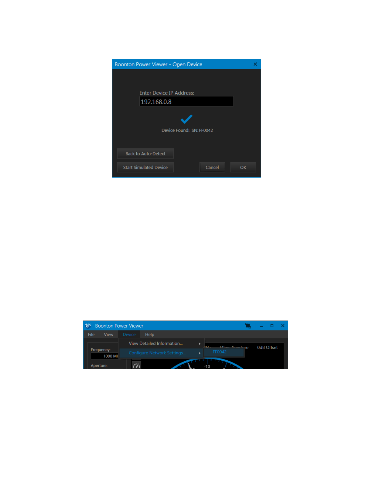
5. The software will then verify the IP.
Figure 2 - TCPIP Search Success
6. Click OK to open the device.
7. The application will immediately begin taking power measurements.
Auto-detect
If the Cancel button is selected, the user will be returned to the Open Device window with
Auto-Detect of USB devices disabled. To return to the Open Device window with Auto-Detect
with Auto-Detect enabled, select the Back to Auto-Detect button.
3.1.2.3 Configuring the TCP/IP Settings of a Power Sensor
To configure the TCP/IP settings of a Power Sensor, select the device you want to configure under the
File -> Configure Network Settings…menu:
Configure the settings as required using the input boxes within the New Settings section of the window.
When finished, click the Store New Settings…button to apply the changes.
3-4 GENERAL USE & CONFIGURATION Page 13

CPS2000 Series Instruction Manual
3-5 GENERAL USE & CONFIGURATION Page 14
CPS2000 Series Instruction Manual
3.2 Configuring a Power Sensor
The CPS2000 GUI application provides a simple device configuration UI.
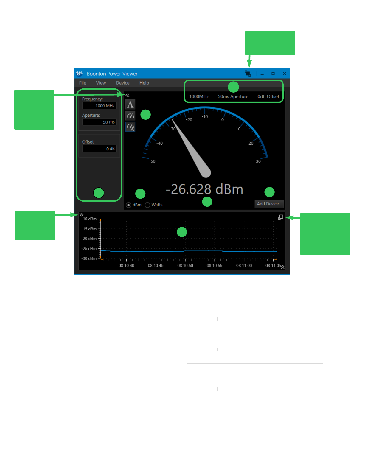
Figure 3 - Software Overview
1
Settings panel, including Frequency,
Aperture, and Offset settings.
3
Units selection
Aperture
1 ms - 2 s
The aperture time is the total time the
sensor observes the input signal to
make one power measurement.
4
Visualization selected. Options
include Text-Only, Gauge-Only, and
Text + Gauge.
Offset
+/-200 dB
This feature provides the ability to
apply corrections to measurements
when RF devices are between the
sensor and DUT.
5
6
Power Measurement
Add Device…button for adding
additional devices
2
Live Power vs. Time graph
(units are dBm only)
7
Applied settings
1
2
3
6
4
7
5
Always-on-Top
Feature
Show/Hide
Global
Settings
Panel
Show/Hide
Y-Axis
Configuration
Undock & resize
Live Power graph
with Always-on-
Top feature
3-6 GENERAL USE & CONFIGURATION Page 15

CPS2000 Series Instruction Manual
3.3 Connecting to Multiple Power Sensors
The CPS2000 GUI application supports connecting multiple devices. To connect to additional devices,
click the Add Device… button.
To toggle the view between single and multiple sensor readings, navigate to View -> Graph -> All
Channels or No Channels.
Figure 4 - Multiple Device View
3-7 GENERAL USE & CONFIGURATION Page 16

CPS2000 Series Instruction Manual
1
Global settings panel, affects all devices
that are linked to the global settings
5
Applied device settings for each device
2
Device label –A user configurable label
for a Power Sensor or Ratio
6
Toggle buttons to configure or remove a
specific Power Sensor or Ratio
3
Color selector
7
Adds a ratio between two power
measurements
4
Graph toggle checkbox
3.4 Upgrading the Firmware on a Power Sensor
To determine the current firmware version on a CPS power sensor, navigate to Device -> View Detailed
Information -> and select the sensor of interest.
3-8 GENERAL USE & CONFIGURATION Page 17

CPS2000 Series Instruction Manual
To upgrade firmware, the CPS2000 GUI application includes a utility for loading firmware onto a
CPS2000 power sensor. The utility is accessible using the File -> Upgrade Device Firmware… menu:
Figure 5 - Firmware Upgrade Menu
To load new firmware onto a power sensor, select it from the list of devices, select an upgrade file, and
then click the Start Upgrade button.
Figure 6 - Firmware Upgrade Process
When the firmware loading process has completed, the power sensor will automatically be reconnected
and power measurements will automatically startup again.
3-9 GENERAL USE & CONFIGURATION Page 18
CPS2000 Series Instruction Manual
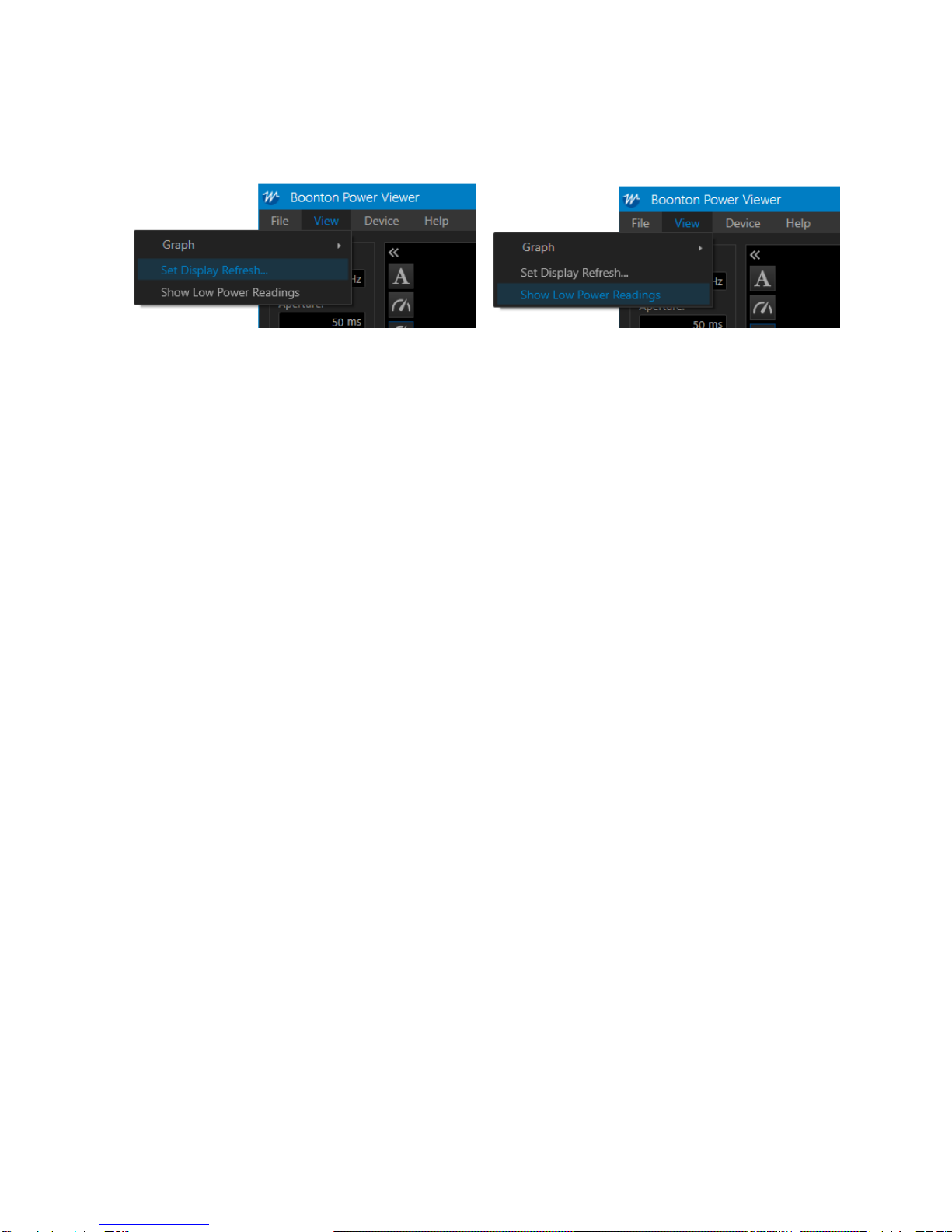
3.5 Other Features
The CPS2000 GUI includes additional features described below.
3.5.1 Set Display Refresh
Users can select the display refresh rate from x to y.
3.5.2 Show Low Power Readings
The CPS2000 power sensor can detect power levels below the specified measurement range. Users can
elect to display these readings by selecting Show Low Power Readings. Otherwise, the when power
levels are below the specified range, the display will read “Too Low” (default setting).
3-10 GENERAL USE & CONFIGURATION Page 19

CPS2000 Series Instruction Manual
4Troubleshooting
4.1 Recovery After a Failed Firmware Upgrade
If a failure is encountered when attempting to upgrade a device, such as if the cable is disconnected
during an upgrade, the device may be left in a state that prevents operation of the normal upgrade
procedure.
If this occurs, the device can still be recovered. To recover the device, follow these steps:
1. Open a Windows Command Prompt window
2. Within the command prompt, navigate to the CPS2000 GUI application’s directory:
> cd C:\Program Files(x86)\Boonton\CPS2000
Note: This location depends on the location where the application was installed. If
you installed the application to a different location, you will need to use a different
path.
3. Execute the following command, replacing <path> with the path to your firmware upgrade
.sb file.
> blhost.exe --usb 0x1cb5,0x2000 receive-sb-file <path>
4. Allow the upgrade to complete.
5. When finished, execute the following command:
> blhost.exe --usb 0x1cb5,0x2000 reset
6. The device will reset and will then be available for use in the CPS2000 GUI application.
5Boonton Resources on RF Power Measurements
Information regarding power measurement and Boonton Power Sensor products is available free of
charge from the Resource Library section of the Boonton website. All Boonton power sensor instruction
manuals cover the details of RF power measurement techniques. The following links highlight a few of
the available application notes, articles, webinars and white papers related to RF Power measurements
and techniques:
•Principles of RF Power Measurements:
http://www.boonton.com/resource-library/power-measurement-reference-guide
•Videos:
http://boonton.com/resource-library?brand=Boonton&go=videos
•Application Notes:
http://www.boonton.com/resource-library?brand=Boonton&go=application_notes
4-1 TROUBLESHOOTING AND RESOURCES Page 20
Other manuals for CPS2000
1
Table of contents
Other Boonton Accessories manuals


