Booth BAR2H User manual

Booth D
i
s
p
e
n
s
e
r
s
Ltd, Moor
Park Avenue, B
l
a
c
k
poo
l
,
L
a
nc
a
s
h
i
r
e
,
FY2 0LZ, U
K
+44 1253
501800
Product
M
a
nu
a
l
B
A
R
2
H
Shelf
M
oun
t
e
d
Beer
C
oo
l
e
r
s
3
B
6993
-
O
R
12
1
I
n
t
r
odu
c
t
i
on
C
on
t
e
n
t
s
S
ec
t
i
on
P
a
g
e
S
ec
t
i
on
P
a
g
e
I
n
tr
oduc
t
i
on
2
F
a
u
l
t
f
i
nd
i
ng
8
S
p
e
c
i
f
i
c
a
t
i
on
&
I
n
s
t
a
ll
a
t
i
on
3
Spare
p
a
rt
s
9
M
od
e
l
N
u
m
b
e
r
i
ng
C
on
v
e
n
t
i
on
4
R
e
m
o
v
a
l
,
Tr
a
n
s
po
rt
a
t
i
on
&D
i
s
po
s
a
l
10
S
ch
e
m
a
t
i
c
s
5
-
7
I
n
t
r
odu
c
t
i
on
The
BAR2H
i
s
an
i
c
e
bath coo
l
e
r
d
e
s
i
gn
e
d
to
p
r
o
v
i
d
e
ch
ill
e
d
product
f
o
r
under counter
a
pp
li
c
a
t
i
on
s
.
The system uses a bath water r
e
c
i
r
cu
l
a
t
i
on
system and
python to
generate and
m
a
i
n
t
a
i
n
op
t
i
m
u
m
d
r
i
n
k
temperature at the
po
i
n
t
o
f
d
i
s
p
e
n
s
e
.
The
BAR2H
coo
l
e
r
i
s
d
e
s
i
gn
e
d
f
o
r
e
ff
e
c
t
i
v
e
p
e
r
f
o
r
m
a
nc
e
and
i
m
p
r
o
v
e
d
energy
e
ff
i
c
i
e
nc
y
.
It
i
s
i
d
ea
l
f
o
r
a range
o
f
a
pp
li
c
a
t
i
on
s
,
i
t
s
compact
s
i
z
e
i
d
ea
ll
y
s
u
i
t
e
d
to
under counter
i
n
s
t
a
ll
a
t
i
on
s
.
S
a
f
e
t
y
The
BAR2H
Hydrocarbon
un
i
t
s
use
R290
(Care
40,
Propane). B
e
l
o
w
are some
s
a
f
e
ty
po
i
n
t
s
w
h
i
ch
t
h
e
end user must adopt
to
m
i
t
i
g
a
t
e
the r
i
s
k
o
f
un
s
a
f
e
cond
i
t
i
on
s
a
r
i
s
i
ng.
S
e
rv
i
c
e
must on
l
y
be
c
a
rr
i
e
d
out by
a
s
u
i
t
a
b
l
y
qu
a
li
f
i
e
d
r
e
f
r
i
g
e
r
a
t
i
on
e
ng
i
n
ee
r
.
The un
i
t
s
hou
l
d
be
i
s
o
l
a
t
e
d
f
r
o
m
the
e
l
e
c
tr
i
c
i
ty
s
upp
l
y
b
e
f
o
r
e
r
e
m
o
v
a
l
o
f
the
co
v
e
r
s
.
Do not
damage the r
e
f
r
i
g
e
r
a
t
i
on
c
i
r
cu
i
t
.
V
e
n
t
il
a
t
i
on
op
e
n
i
ng
s
must be
c
l
ea
r
o
f
ob
s
tr
uc
t
i
on
s
.
There must be a gap
o
f
at
l
ea
s
t 100mm
between the
a
pp
li
a
nc
e
and
a w
a
ll
or other r
e
s
tr
i
c
t
i
on.
Where
e
l
e
c
tr
i
c
a
l
componentsare r
e
p
l
a
c
e
d,
the new component must be o
f
the same ty
p
e
.
Operate
un
i
t w
i
t
h
i
n
(
a
m
b
i
e
n
t)
op
e
r
a
t
i
ng
temperatures;
10°C to
32
°
C
.
2
11
Introduction

Specificationand
I
n
s
t
a
ll
a
t
i
on
Removal,Transportation and
Di
s
po
s
a
l
I
m
po
rt
a
n
t:
Before removal
from
the installation, ensure all electrical, product
and
g
a
s
c
onn
ec
t
i
on
s
are d
i
s
c
onn
ec
t
e
d
.
Disposal
of
Scrap Un
i
t
s
It
i
s
ill
e
g
a
l
to
s
i
m
p
l
y
scrap a r
e
f
r
i
g
e
r
a
t
i
on
un
i
t
.
B
e
f
o
r
e
a
un
i
t
can be scrapped
it
must
f
i
r
s
t
have
t
h
e
gas removed
by
a
s
p
e
c
i
a
li
s
t
u
s
i
ng
s
p
e
c
i
a
li
s
t
e
qu
i
p
m
e
n
t
.
P
l
ea
s
e
contact
Booth D
i
s
p
e
n
s
e
r
s
Ltd.,
who
will
be happy
to
p
r
o
v
i
d
e
a
quo
t
a
t
i
on
f
o
r
d
i
s
po
s
a
l
.
T
r
a
n
s
po
r
t
a
t
i
on
I
m
po
r
t
an
t
: T
h
i
s
un
i
t
must be transported
i
n
an
up
r
i
gh
t
po
s
i
t
i
on
As w
i
t
h
a
ll
r
e
f
r
i
g
e
r
a
t
i
on
systems,
i
rr
e
p
a
r
a
b
l
e
damage can be caused
by
l
a
y
i
ng
the
un
i
t on
i
t
s
s
i
d
e
o
r
even tr
a
n
s
po
rt
i
ng
up
s
i
d
e
down.
Where the un
i
t
i
s
transported
by
a
c
a
rr
i
e
r
,
the carton
s
hou
l
d
a
l
w
a
y
s
be marked
i
n
a
con
s
p
i
cuou
s
manner, the correct up
r
i
gh
t
po
s
i
t
i
on
i
n
w
h
i
ch
it
must be
h
a
nd
l
e
d.
If
a
un
i
t
has been transported
i
nco
rr
e
c
t
l
y
it
s
hou
l
d
be
p
l
a
c
e
d
i
n
the correct up
r
i
gh
t
po
s
i
t
i
on
and
l
e
f
t
f
o
r 24
hours b
e
f
o
r
e
a
tt
e
m
p
t
i
ng
to run
the
s
y
s
t
e
m
.
F
a
il
u
r
e
to
observe the above
p
r
e
c
a
u
t
i
on
s
cou
l
d
s
e
r
i
ou
s
l
y
damage the system, and w
ou
l
d
v
o
i
d
a
n
y w
a
rr
a
n
ty
.
10
S
p
ec
ifi
ca
t
i
on
Di
m
en
s
i
on
s
453
mm
(W)
425mm(D) + 40mm
f
o
r
Product
C
o
il
s
282
mm
(H)
C
o
m
p
r
e
ss
o
r
H
u
y
a
i
C
ub
i
g
e
l
N
LY
45
R
A
Dry W
e
i
gh
t
25
k
g
T
h
i
s
product
con
t
a
i
n
s
P
r
opane
Refrigerantgas
with
a
GWP of 3 in
a
hermetically
s
ea
l
ed
s
y
s
t
e
m
S
upp
l
y
230
V
a
c
/
50
H
z
R
e
f
r
i
ge
r
an
t
R290
80g
Rated
I
npu
t
300
W
Climatic
C
l
a
ss
N
Rated
C
u
rr
en
t
1.25
A
Fuse
R
a
t
i
ng
5
A
I
n
s
t
a
ll
a
t
i
on
The un
i
t
must be
i
n
s
t
a
ll
e
d
by
a competentperson,
on
a
firm
l
e
v
e
l
s
u
r
f
a
c
e
c
a
p
a
b
l
e
o
f
s
uppo
rt
i
ng
t
h
e
w
e
i
gh
t
o
f
the
m
a
ch
i
n
e
when the bath
i
s
f
ill
e
d.
It
i
s
i
m
po
rt
a
n
t
that the v
e
n
t
il
a
t
i
on
op
e
n
i
ng
s
i
n
t
h
e
m
a
ch
i
n
e
are
not
b
l
oc
k
e
d
to
a
ll
o
w
the
f
r
ee
movement o
f
a
i
r
.
I
n
a
d
e
qu
a
t
e
v
e
n
t
il
a
t
i
on
will
shorten the
li
f
e
o
f
the
f
r
i
dg
e
s
y
s
t
e
m
.
Note:
At
t
h
i
s
stage
do not
connect the
unit to
the electrical
s
upp
l
y
Ensure that the v
e
n
t
il
a
t
i
on
op
e
n
i
ng
s
are
not
b
l
oc
k
e
d,
to
a
ll
o
w
f
r
ee
movement o
f
a
i
r
through
the
un
i
t
.
Failure
to do
t
h
i
s
will
s
e
r
i
ou
s
l
y
affect the reliability
of
the f
r
i
dge
,
invalidate the warranty and shorten the life
of
the fridge
s
y
s
t
e
m
.
L
oc
a
t
e
a
con
t
a
i
n
e
r
beneath the bath
o
v
e
r
f
l
o
w to
prevent any water
s
p
ill
a
g
e
as the bath
i
s
f
ill
e
d
and when
i
c
e
i
s
f
o
r
m
e
d
i
n
the
b
a
t
h.
Fill
the bath u
s
i
ng
co
l
d
water
through
the
‘
B
a
t
h
F
ill
’
op
e
n
i
ng
on
the
top
o
f
the
m
a
ch
i
n
e
un
t
il
water
i
s
d
i
s
p
l
a
c
e
d
f
r
o
m
the
o
v
e
r
f
l
o
w
.
Connect the d
i
s
p
e
n
s
e
python to
the
‘
R
e
c
i
r
cu
l
a
t
i
on
’
F
l
o
w
and
R
e
t
u
r
n.
Connect the
product to
the
s
t
a
i
n
l
e
ss
s
t
ee
l
product
co
il
s
.
Connect the un
i
t to
the
e
l
e
c
tr
i
c
a
l
s
upp
l
y
and
turn
on.
A
f
t
e
r
a short
d
e
l
a
y
the compressor and
f
a
n
s
will
s
t
a
rt
.
The un
i
t
will
now
b
e
g
i
n
to
reduce the bath water temperature. Once the water
i
s
at
t
h
e
correct temperature, an
i
c
e
bank
will
b
e
g
i
n
to
f
o
r
m
.
As the
i
c
e
b
e
g
i
n
s
to
f
o
r
m
,
a
s
m
a
ll
amount o
f
water
will
be
d
i
s
p
l
a
c
e
d.
Oncea
full
i
c
e
bank
i
s
produced, the
f
a
n
and compressor
will
s
w
i
t
ch
off
and the
m
a
ch
i
n
e
i
s
ready
f
o
r
u
s
e
.
Note: The t
i
m
e
taken
f
o
r
the
un
i
t to
reach
op
e
r
a
t
i
ng
temperature
will
vary
d
e
p
e
nd
i
ng
on
a
m
b
i
e
n
t
temperature, hu
m
i
d
i
ty
and the temperature
o
f
the
i
nco
m
i
ng
water
s
upp
l
y
.
3
Specification and Installation
Removal, Transportation & Disposal
Model
N
u
m
b
e
r
i
ng
Spare P
a
r
t
s
SPC8/2
Pump –
1
A
5176
SPC12/4
Pump –
1
A
5177
E
li
w
e
ll
C
on
tr
o
ll
e
r –
1
A
5362
DFX
C
on
tr
o
ll
e
r –
1
A
6310
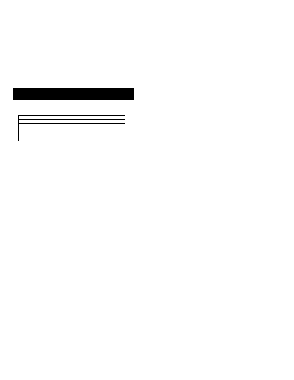
4 9
UNIT NUMBER (BAR2H) (X) (Y) (Z)
KEY:
BAR2H
BASE TYPE
(X)
PUMP
(Y)
CONTROL OPTION
(Z)
NO OF COILS/DECK OPTION
REFERENCE
PART #
DESCRIPTION
(X)
PUMP
2
1A5176
SPC8/2 PUMP
4
1A5177
SPC12/4
(Y)
CONTROL
M
1A5361
MECHANICAL
E
1A5362
ELIWELL
D
1A6310
DFX CONTROL
(Z)
DECK
0
1A6305
NO COILS
1
1A6306
1 COIL
2
1A6307
2 COILS
3
1A6308
3 COILS
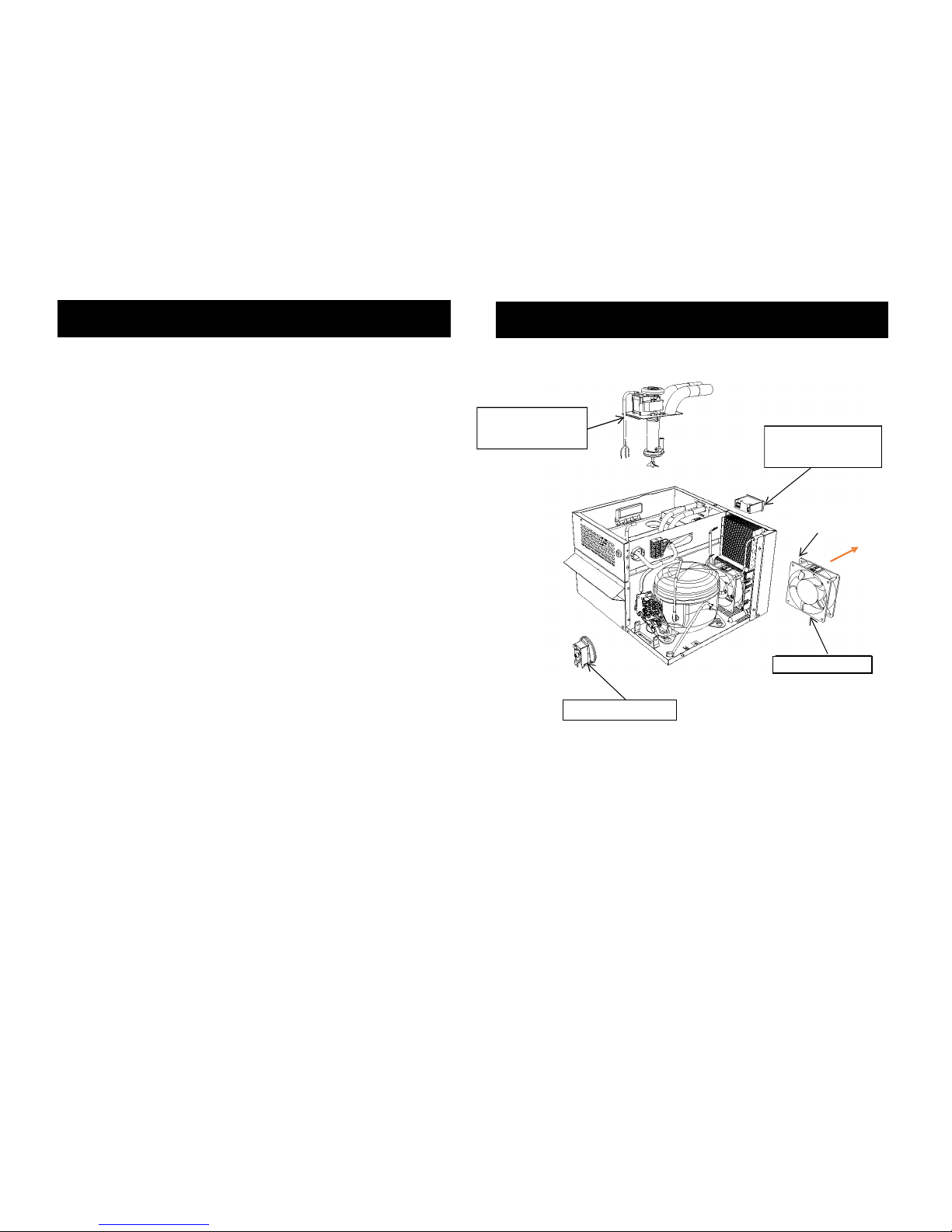
Mechanical Stat –1A5361
1B5514 –Cooling Fan
Model Numbering Convention
Spare Parts
Electrical Connections
this side
D
i
r
e
c
t
i
on
o
f
a
i
r
fl
o
w

Fault
F
i
nd
i
ng
S
c
h
e
m
a
t
i
c
P
r
i
o
r to
any
f
a
u
l
t
f
i
nd
i
ng,
p
l
ea
s
e
ensure
a
ll
conn
e
c
t
i
on
s
to
the
ch
ill
e
r
are sound and t
h
a
t t
h
e
i
nco
m
i
ng
s
upp
ly
i
s
turned
on.
A
l
s
o,
ensure t
h
a
t
a
ll
e
l
e
ct
r
i
cal
l
conn
e
c
t
i
on
s
to
the
ch
ill
e
r
and
i
n
the
ch
ill
e
r
are secure and
i
n
good
cond
i
t
i
on,
the power
i
s
on
and that the ch
ill
e
r
has had
a
d
e
qu
a
t
e
t
i
m
e
to
reach
op
e
r
a
t
i
ng
t
e
m
p
e
r
a
t
u
r
e
.
NOTE:
I
s
o
l
a
t
e
from
m
a
i
n
s
before removing any
p
a
n
e
l
s
No Drinks
Water supply
Check connections to water supply.
Check water supply is turned on.
Check water supply is turned on.
Check system for blockages.
Check system for blockages.
Frozen product coil
Check thermostat/temperature probe is correctly
located into the bath probe well.
Check the agitator is running. If supply voltage is
present renew agitator assembly.
If agitator is running with no water agitation check
agitation blades.
Warm Drinks
Insufficient air flow through the
fridge.
Check that the condenser is not blocked.
Check for blockages and obstructions to
ventilation grills.
Cooling Fans Not running
Check supply to cooling fans.
If supply present replace fans.
If supply not present check connections,
thermostat, high side protection (digital thermostat
only) and fuse.
Compressor not running
Check supply to Compressor.
If supply present return for repair.
If supply not present check connections,
thermostat, high side protection (digital thermostat
only) and fuse.
Fridge failure
If compressor & fan are running and there is no
cooling, return for repair.
8
Eliwell
Wiring
S
c
h
e
m
a
t
i
c
Schematic
Fault Finding
5

S
c
h
e
m
a
t
i
c
S
c
h
e
m
a
t
i
c
DFX Wiring
S
c
h
e
m
a
t
i
c
6
M
ec
h
a
n
i
ca
l
Wiring
S
c
h
e
m
a
t
i
c
7
Schematic
Schematic
Table of contents
Other Booth Accessories manuals


