Booth DRY125 User manual

Booth Dispensers Ltd, Moor Park Avenue,
Blackpool, Lancashire
Tel +44 (0)1253 501800
www.booth-dispensers.co.uk
Installation Instructions
DRY125 Kitchen Cooler
Part Number 3B3967 Issue OR [18/06/09}
Booth Kitchen Cooler
Installation Instructions
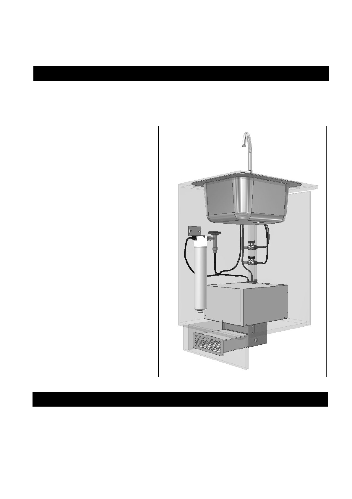
The Booth Kitchen Cooler is designed to be fitted into a kitchen cupboard, ideally below the sink,
in close proximity to both mains water and electrical supplies. If an electrical socket is not close to
the intended location of the cooler, one should be fitted by a qualified electrician. The cooler is
intended to be installed in conjunction with a water filter and dispense tap which are available as an
optional kit from Booth Dispensers. If
alternative parts are used, the instructions
for installing them should be followed to
make the connections to the mains water,
and the cooler should be connected
between the outlet of the filter and the
tap. These instructions cover the
installation of the cooler with the
optional kit from Booth Dispensers Ltd.
The cooler is supplied with an air inlet
duct that will need to be fitted as per the
illustration opposite. This allows cool air
to be drawn in from a vent in the kick-
board at the front of the cupboard, and
warm air is blown out through the rear
panel in the cupboard. The rear panel of
the cupboard should not be too close to
the wall, and a gap of 50mm will be
sufficient in most cases. In virtually all
installations, the warm air will then be
able to escape from this area easily, and
no additional ventilation will be
necessary. For example, a gap of 15mm
between the cupboard base and the top of
the kick-board will be sufficient.
However, if the back of the cupboard is
completely sealed to the wall, and there
is no way for warm air to escape, the
cooler will not work correctly, and
additional ventilation will be necessary to
allow the warm air to escape.
1. IMPORTANT: Before making any cuts into the cupboard or kick board, ensure the area
to be cut is free from water pipes or electrical cables. There is a risk of serious injury or
death if electrical cables are cut, and significant damage to property if a water pipe is cut.
2. Before installation, ensure there is an electrical socket in close proximity to the intended site of
the cooler. If not, it will be necessary to have one fitted by a qualified electrician.
Introduction
Installation Instructions
3. Also ensure that there is adequate space at the back of the cabinet and a way for warm exhaust
air to escape, a 50mm gap between the
panel and wall should be sufficient.
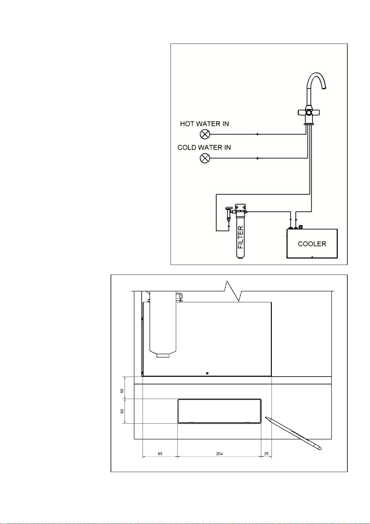
4. Identify the best location for the cooler,
tap and filter by reference to the
illustration above, the water circuit
diagram opposite, the tap and filter
instructions and the parts themselves.
Take care now in planning the
connection to the water mains, routing
of flexible tubes and location of
components to ensure the installation is
as unobtrusive as possible.
5. It is also necessary to ensure that the air
inlet duct will not clash with any legs
or other obstacles in the cupboard kick
space, and that the cooler and filter will
not clash with any other fixtures within
the cupboard such as drainage
components.
6. Using the Cooler template A, mark the
position of the cooler sides on the base
of the cupboard, and the position of the
opening for the air inlet. Using
template B, mark the opening for the
exhaust air in the back of the cabinet.
Remove the templates and cut out the
two openings.
7. Referring to the
drawing opposite,
mark out the
position of the
opening in the
kick-board, and
cut out the air inlet
hole in the kick
board. Note:
Dimensions are
measured from
the left side and
bottom of the
cooler. The left
side of the cooler
should have been
marked onto the
base in item 5
above.
8. Insert the right-
angled spigot into
the hole in the
base of the cabinet.
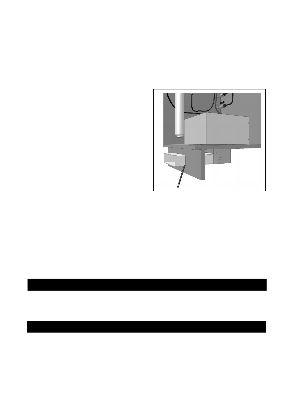
9. Fit the length of rectangular duct through the cut-out in the kick board and into the spigot.
Ensure it is fully engaged into the socket and mark the ducting where it protrudes from the kick
board. Remove the duct and cut to length.
10. Refit the rectangular duct, and attach the outlet grill to the kick-board using 4 screws, this will
retain the duct in position.
11. Now place the cooler in position over the air inlet opening, ensuring the outlet grille on the back
of the machine aligns with the back of the cabinet, and that the cooler is in the correct position
as marked in point 4. Note: It is advisable to place a sheet of cardboard or towel beneath the
cooler to help slide it into position, and protect the base of the cupboard. This must be
removed once the cooler is in position.
12. Secure the cooler in position using one of the
fixing brackets supplied. Loosen the cooler
screw at the front centre, near the base, insert the
bracket and replace screw. Then secure the
bracket by driving the self tapping screw to the
cabinet base.
Important Note: The ventilation openings must
align with the cut-outs in the cabinet to ensure
reliable operation of the cooler, and the cooler
should be fixed in position to prevent the cooler
being moved inadvertently.
13. Fit the tap and filter by following the
instructions contained in the kit, but do not make
the final water connections between the filter
outlet and tap.
14. Connect the outlet of the filter to the cooler inlet (left connection) by simply pushing the blue
water tube fully home into the fitting. Fit insulation to the tube between the tap and cooler, and
connect the tube to the cooler outlet. Note: If cutting the tube to length, it is important that
the cut is perpendicular to the tube, otherwise difficulties may be experienced with the
push-fit fittings sealing.
15. Turn on the water supply and ensure all connections are sound. Open the filtered water tap and
flush approximately 10 litres through the system.
16. Connect the power lead from the chiller to an electrical socket, and turn the power on. The
compressor and fan will start indicating the fridge is working correctly. After a few minutes, the
fan and compressor will turn off indicating the fridge has reached its normal operating
temperature and is ready for use.
It is illegal to simply scrap a refrigeration unit. Before a unit can be scrapped it must first have the
gas removed by a specialist using specialist equipment. Please contact Booth Dispensers ltd who
will be happy to provide a quotation for disposal.
Important: This unit must be transported in an upright position
As with all refrigeration systems, irreparable damage can be caused by laying the unit on its side
or even transporting upside down. Where the unit is transported by a carrier, the carton should
always be marked in a conspicuous manner, the correct upright position in which it must be
handled. If a unit has been transported incorrectly it should be placed in the correct upright
position and left for 24 hours before attempting to run the system. Failure to observe the above
precautions could seriously damage the system.
Disposal of Scrap Unit
Transportation of refrigeration equipment
Table of contents
Other Booth Accessories manuals


