Booth BAR3 User manual
Product Manual
BAR3
Shelf Mounted Beer Coolers
Part Number 3B6694 Issue C

Contents
Introduction
The BAR3 is an ice bath cooler designed to provide chilled product in a dispense application. The
system uses a bath water recirculation system and python to generate and maintain optimum drink
temperature at the point of dispense.
The BAR3 cooler is designed for effective performance and improved energy efficiency. It is ideal for a
range of applications, its compact size ideally suited to under counter installations.
Safety
The BAR3 units use different refrigerants dependant on the model selected. BAR300 models use R134a
refrigerant, whereas BAR3H Hydrocarbon units use R290 (Care 40, Propane). Below are some safety
points which the end user must adopt to mitigate the risk of unsafe conditions arising.
Service must only be carried out by a suitably qualified refrigeration engineer.
The unit should be isolated from the electricity supply before removal of the covers.
Do not damage the refrigeration circuit.
Ventilation openings must be clear of obstructions.
There must be a gap of at least 100mmbetween the appliance and a wall or other restriction.
Where electrical components are replaced, the new component must be of the same type.
Operate unit within (ambient) operating temperatures; 10°C to 32°C.
Section
Page
Section
Page
Introduction & Safety
2
Fault finding
9
Specification & Installation
3-4
Spare parts
10
Model Numbering Convention
5
Removal, Transportation
& Disposal
12
Schematics
6-8
Introduction

Specification
BAR300
Dimensions
570mm(W)
450mm(D)
280mm(H)
Compressor
Tecumseh
THB4422Y
Dry Weight
24kg
This product contains R134a Refrigerant gas with
a GWP of 1430 in an hermetically sealed system
Wet Weight
39kg
Supply
230Vac/50Hz
Refrigerant
R134a 145g
Rated Input
400W
Climatic Class
N
Rated Current
5A
Fuse Rating
5A
IP Rating
N/A
BAR3H
Dimensions
570mm(W)
450mm(D)
280mm(H)
Compressor
Cubigel
NLY60RAa
Dry Weight
28kg
This product contains R290 Propane Refrigerant
gas with a GWP of 3 in an hermetically sealed
system
Wet Weight
39kg
Supply
230Vac/50Hz
Refrigerant
R290a 70g
Rated Input
500W
Climatic Class
N
Rated Current
5A
Fuse Rating
5A
IP Rating
N/A
Installation
The unit must be installed by a competent person, on a firm level surface capable of supporting the
weight of the machine when the bath is filled, and all connections made.
Ensure that the ventilation openings are not blocked to allow free movement of air through
the unit. Failure to do this will seriously affect the reliability of the fridge, invalidate
the warranty and shorten the life of the fridge system.
The water bath requires filling prior to switch on. Fill the bath using cold water through the
opening on the top of the machine until water is displaced from the overflow. Discontinue
filling and replace the overflow cap.
Specification and Installation

Connect the dispense python to the ‘Recirculation’ Flow and Return.
Connect the product to the stainless steel product coil.
BAR3H - For details on how to install Tube in Tube/Scope dispense, please contact Brandels at
http://www.brandels.co.uk/. Alternatively, please phone on 01253 501800 to speak to one of our
advisors.
Connect the unit to mains power.
Turn on the mains voltage supply. After a short delay the compressor fans will activate. The unit
will now begin to reduce the bath water temperature.
Continue to monitor the bath level as the python fills with water. Top up if necessary.
Once the water is at the correct temperature an ice bank will begin to form. As the ice begins to
form, a small amount of water will be displaced.
Once a full ice bank is produced, the fans and compressor will switch off and the machine is ready
for use.
Specification and Installation

Unit number BAR3(Z) ( Y ) ( X ) ( W )
Key:
(Z) Refrigerant Type
(Y) Pump Type
(X) Module Type
(W) Deck
(V) Number of coils
- - - Coil type and number of coils repeated as necessary
Reference
Part #
Description
(Z)
REFRIGERANT
0
1S0409
R134a Refrigerant
H
1S0615
R290 (Hydrocarbon)
Refrigerant
(Y)
PUMP
2
1A5176
SPC8/2 pump
4
1A5177
SPC12/4
6
1A6273
Saber Pump Assy (BAR3H)
1A6292
Saber Pump Assy (BAR30)
(X)
MODULE
M
1A5361
Mechanical Control
E
1A5362
Eliwell Control
D
1A6310
DFX Control
(W)
DECK
0
1A5746
No Coils
1
1A5747
1 Coil
2
1A5748
2 Coils
3
1A5749
3 Coils
4
1A5750
4 Coils
5
1A6201
Tube in Tube / Scope
Model Numbering Convention

BAR3H & BAR300 Eliwell Wiring Schematic
Schematic
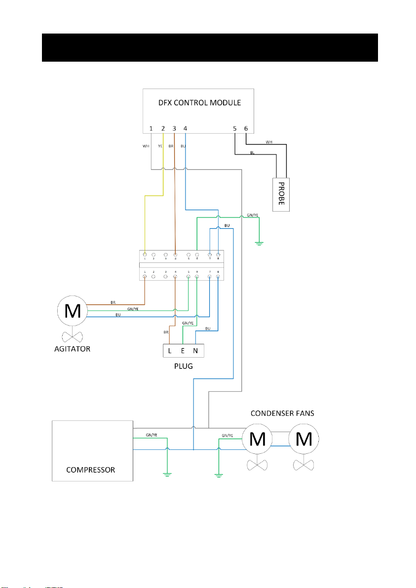
BAR3H & BAR300 DFX Wiring Schematic
Schematic

BAR3H & BAR300 Mechanical Wiring Schematic
Schematic

Prior to any fault finding, please ensure all connections to the chiller are sound and that the incoming supply
is turned on. Also ensure that all electrical connections to the chiller and in the chiller are secure and in
good condition, the power is on and that the chiller has had adequate time to reach operating temperature
NOTE: Isolate from mains before removing any panels
No
Drinks
Water supply
Check connections to water supply.
Check water supply is turned on.
Check system for blockages.
Frozen product
coil
Check thermostat/temperature probe is
correctly located into the bath probe well.
Check the agitator is running. If supply
voltage is present renew agitator
assembly.
If agitator is running with no water
agitation check agitation blades.
Warm
Drinks
Insufficient air flow
through the fridge.
Check that the condenser is not blocked.
Check for blockages and obstructions to
ventilation grills.
Cooling Fans Not
running
Check supply to cooling fans.
If supply present replace fans.
If supply not present check connections,
thermostat, high side protection (digital
thermostat only) and fuse.
Compressor not
running
Check supply to Compressor.
If supply present return for repair.
If supply not present check connections,
thermostat, high side protection (digital
thermostat only) and fuse.
Fridge failure
If compressor & fan are running and there
is no cooling, return for repair.
Fault Finding
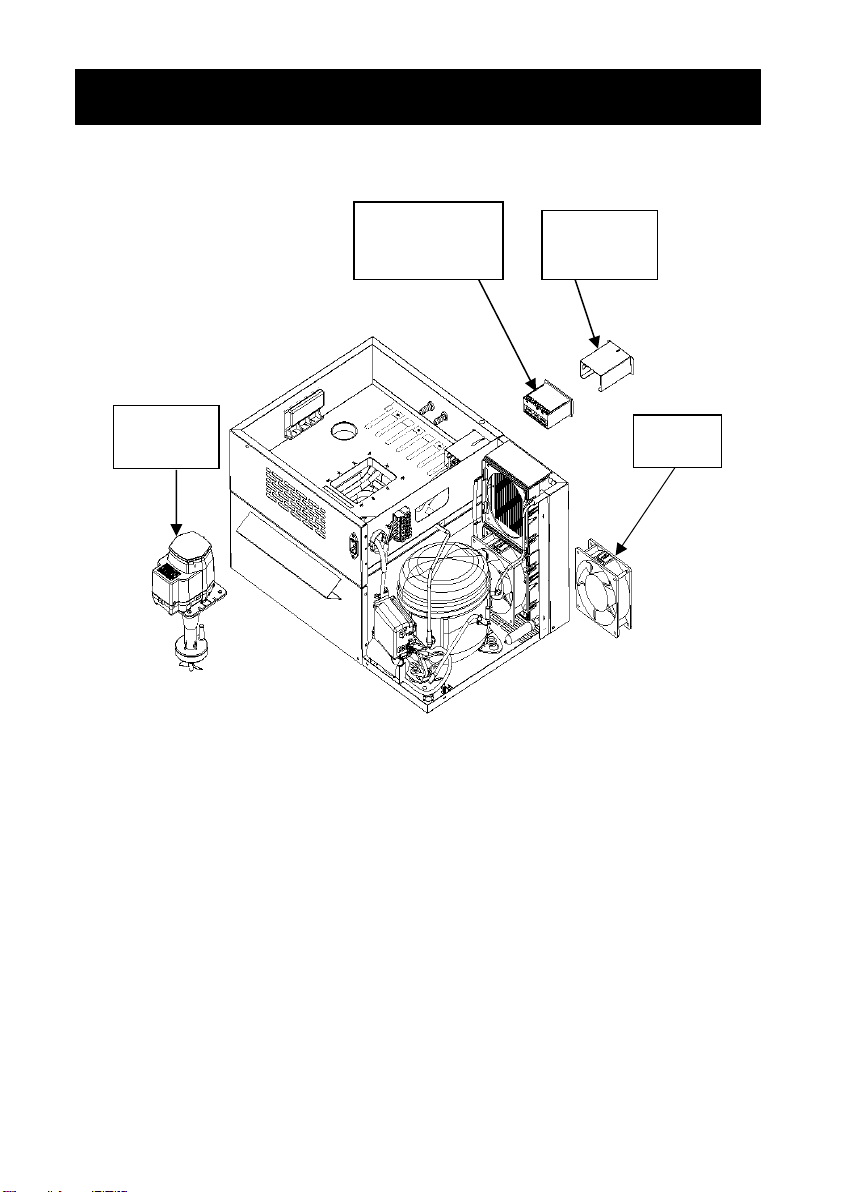
BAR300 Spares
1B5514
Cooling Fan
1A5362
Eliwell Control Module
1A6310
DFX Control Module
Pump
Refer to table
on Page 5
1A5361
Mechanical
Control Module
Spare Parts

BAR3H Spares
Spare Parts
3B6090
Coaxial Elbow
1B5514
Cooling Fan
1A5362
Eliwell Control Module
1A6310
DFX Control Module
1A5361
Mechanical
Control Module
INSU77
Polar Clean
Elbow
Pump
Refer to table
on Page 5

Important: Before removal from the installation, ensure all electrical, product and gas connections are
disconnected.
Disposal of Scrap Units
It is illegal to simply scrap a refrigeration unit. Before a unit can be scrapped it must first have the gas removed
by a specialist using specialist equipment. Please contact Booth Dispensers Ltd., who will be happy to provide a
quotation for disposal.
Transportation
Important: This unit must be transported in an upright position
As with all refrigeration systems, irreparable damage can be caused by laying the unit on its side or even
transporting upside down. Where the unit is transported by a carrier, the carton should always be marked in a
conspicuous manner, the correct upright position in which it must be handled.
If a unit has been transported incorrectly it should be placed in the correct upright position and left for 24 hours
before attempting to run the system.
Failure to observe the above precautions could seriously damage the system, and would void any warranty.
Removal, Transportation and Disposal
Booth Dispensers Ltd, Moor Park Avenue, Blackpool,
Lancashire, FY2 0LZ, UK
+44 1253 501800
Table of contents
Other Booth Accessories manuals


