BOQU BQ401 User manual

Integrated Multi-parameter Sensor Operation manual
BQ401 Integrated Multi-parameter
Sensor Operation manual
SHANGHAI BOQU INSTRUMENT CO.,LTD

2
Catalog
Introduction.................................................................................................................................4
1Summary...................................................................................................................................5
1.1 Introduction.......................................................................................................................6
1.2 Technical indexes............................................................................................................. 6
2 Installation............................................................................................................................... 8
2.1 Configuration....................................................................................................................8
2.2 Install Battery....................................................................................................................8
Instrument battery installation................................................................................................ 8
Handheld multi-parmeter battery installation.........................................................................9
2.3 Connection......................................................................................................................10
Connect cable to instrument................................................................................................. 10
Sensor installation.................................................................................................................11
Casing installation and connect to sensor.............................................................................12
3 Operation............................................................................................................................... 13
Measurement Display........................................................................................................... 14
Menu..................................................................................................................................... 15
3.1 Date/Time....................................................................................................................... 15
3.2 System.............................................................................................................................16
Auto Power....................................................................................................................... 16
Air Pressure...................................................................................................................... 16
Salinity..............................................................................................................................17
Probe Info......................................................................................................................... 17
Meter Info......................................................................................................................... 17
3.3 Calibration...................................................................................................................... 17
3.3.1 DO Calibration.........................................................................................................17
One point Calibration....................................................................................................... 18
Two points Calibration..................................................................................................... 18
Sensor Cap........................................................................................................................ 19
3.3.2 Turbidity sensor calibration.....................................................................................20
Zero point calibration....................................................................................................... 20
One point calibration........................................................................................................ 20
Two points calibration...................................................................................................... 20

3
3.3.3 Conductivity sensor calibration............................................................................... 21
One point calibration........................................................................................................ 21
Two points calibration...................................................................................................... 21
3.3.4 pH calibration.......................................................................................................... 22
Three points calibration.................................................................................................... 22
3.3.5 Salinity calibration...................................................................................................23
One point calibration........................................................................................................ 23
Two points calibration...................................................................................................... 23
3.4 Data Log......................................................................................................................... 23
Data Store......................................................................................................................... 23
Data View......................................................................................................................... 23
Data Delete....................................................................................................................... 24
Cal/Reset Cal........................................................................................................................ 24
Connect to computer.............................................................................................................24
4 Maintenance...........................................................................................................................25
4.1 Instrument Maintenance................................................................................................. 25
4.2 Sensor Maintenance........................................................................................................25
DO sensor............................................................................................................................. 26
Turbidity sensor.................................................................................................................... 27
EC/Salinity sensor................................................................................................................ 28
pH sensor.............................................................................................................................. 28
5 FAQ....................................................................................................................................... 28

4
Introduction
Dear Customers,
Thank you very much for choose the high-quality BQ401 handheld multi-parameter
probe and meter from Shanghai BOQU Instrument CO., Ltd. Before you use it,
please read this manual in detail, it will be help you for using and maintenance of this
instrument, and can avoid unnecessary troubles due to improper operation and
maintenance.
Please follow the operating procedures and precautions of this manual.
To ensure that the after-sales protection provided by this instrument is effective,
please do not use and maintain this instrument by methods other than those specified
in this manual.
Any failures and losses caused by non-compliance with the precautions specified in
this manual are not covered by the manufacturer’s warranty, and the manufacturer
does not assume any related responsibilities. Please keep all documents in a safe place.
If you have any questions, please contact our after-sales service department.
When receiving the instrument, please carefully open the package and check
whether the instrument and accessories are damaged due to transportation. If any
damage is found, please contact our company's after-sales service department and
save the packaging for return processing.
When the instrument breaks down, please do not repair it by yourself, please contact
our after-sales service department.

5
1 Summary
BQ401 are independently developed by BOQU Instrument. This combination can measure
temperature, optical dissolved oxygen, fiber optic turbidity, four-electrode conductivity, pH,
salinity, etc. The BQ401 multi-parameter handheld probe can support up to 4 types of probe
measurements. When connected to instrument, these data can be automatically identified. This
meter is equipped with a back light display and operation keyboard. It has comprehensive
functions and simple operation. The interface is simple. It can also show measurement data
storage, sensor calibration and other functions at the same time, and it can export USB data to
achieve more high-end functions. The pursuit of high cost performance is our consistent pursuit.
The dissolved oxygen sensor included in the product uses the world's leading fluorescence
lifetime technology, which is based on the principle of quenching active fluorescence by specific
substances in physics. The significant advantage of this fluorescence method for measuring
dissolved oxygen is that it does not consume oxygen during the measurement process, so there is
no flow rate limitation, at the same time, no preheating, no electrolyte, maintenance and frequent
calibration, and the response time of the BOQU optical dissolved oxygen probe is even lower. Up
to 30 seconds, making dissolved oxygen measurement more accurate, more stable, faster and more
convenient.
6
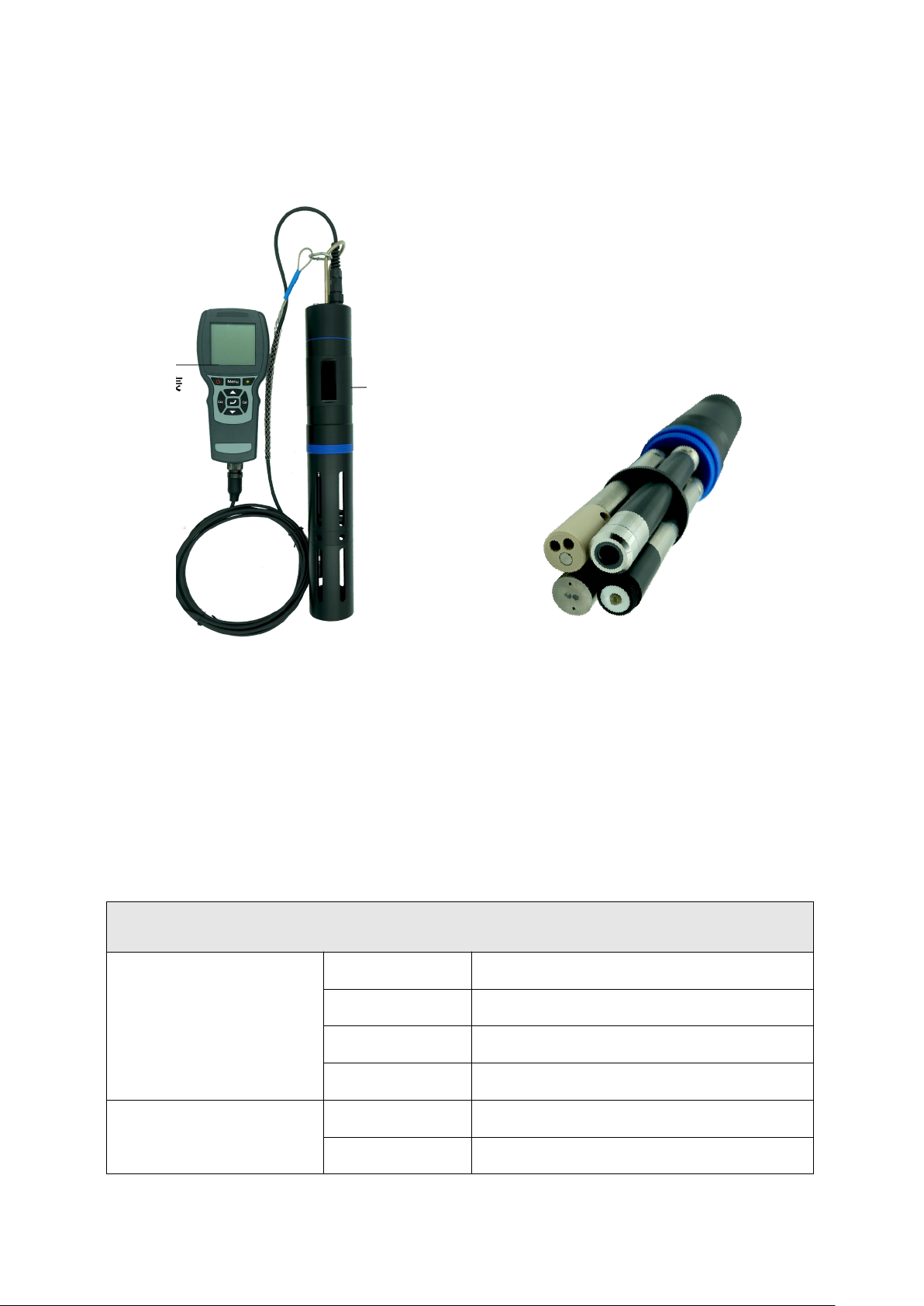
1.1 Introduction
Pic 1-1 Instrument connect sensor→ Pic1-2 Multi-parameter sensor
1.2 Technical Indexes
Multi-parameter Sensor Indexes
Optical dissolved oxygen
sensor
Range
0-20mg/L or 0-200% saturation
Accuracy
±1%
Resolution
0.01mg/L
Calibration
One or two point calibration
Turbidity Sensor
Range
0.1~1000 NTU
Accuracy
±5% or ±0.3 NTU(whichever is greater)

7
Resolution
0.1 NTU
Calibration
Zero, one or two point calibration
Four-electrode conductivity
sensor
Range
1uS/cm~100mS/cm or 0~5mS/cm
Accuracy
±1%
Resolution
1uS/cm~100mS/cm: 0.01mS/cm
0~5mS/cm: 0.01uS/cm
Calibration
One or two point calibration
Digital pH sensor
Range
pH:0~14
Accuracy
0.1
Resolution
0.01
Calibration
Three-point calibration
Salinity sensor
Range
0~80ppt
Accuracy
±1ppt
Resolution
0.01 ppt
Calibration
One or two point calibration
Temperature
Range
0~50℃(no freezing)
Accuracy
±0.2℃
Resolution
0.01℃
Other information
Protection grade
IP68
Size
Φ22×166mm
Interface
RS-485, MODBUS protocol
Power supply
DC 5~12V, current <50mA
Instrument specifications
Size
220 x 96 x 44mm
Weight
460g
Power supply
2 18650 rechargeable batteries
Storage temperature range
-40~85℃
Display
54.38 x 54.38LCD with backlight

8
2 Installation
2.1 Configuration
Standard Configuration
Qty
Unit
Remark
BQ600 Handheld Instrument
1
pc
BQ401 Handheld
multi-parameter sensor
1
pc
Connect 4pcs sensor Max
18650 Rechargeable battery
2
pc
3.7V,use for BQ600
AA battery
2
pc
Use for BQ401
USB connection cable
1
pc
Micro USB
Plug
4
pc
Wristband
1
pc
Screwdriver
1
pc
Use to open battery cover
O-ring
1
pc
Fluorescent cap sealed
replacement
Sponge
2
pc
Fluorescent cap moisturizing
Rubber Sleeve
1
pc
Fluorescent cap storage
Please carefully check whether the product and accessories are damaged before installation. If
damaged, please contact the after-sales service department.
2.2 Install Batter y
BQ600 battery installation
The normal use of the meter requires two lithium batteries, please follow up below steps to install
the batteries:
1) Unscrew the screws on the battery cover and open the battery cover. Note: The screw cannot be
removed, and the battery cover can be opened by screwing it until it stops;
2) Put the battery into the battery box according to the mark on the battery cover of the meter, as
shown in the figure below, pay attention not to install the positive and negative poles reversely.
Data storage
support
Air pressure compensation
Built-in instrument, automatic compensation 50~115kPa
Protection grade
IP67
Timed shutdown
support
9
3) Close the battery cover, pay attention to the sealing ring not to fall off or be uneven, and
confirm that the direction of the battery cover is correct, and tighten the screws.
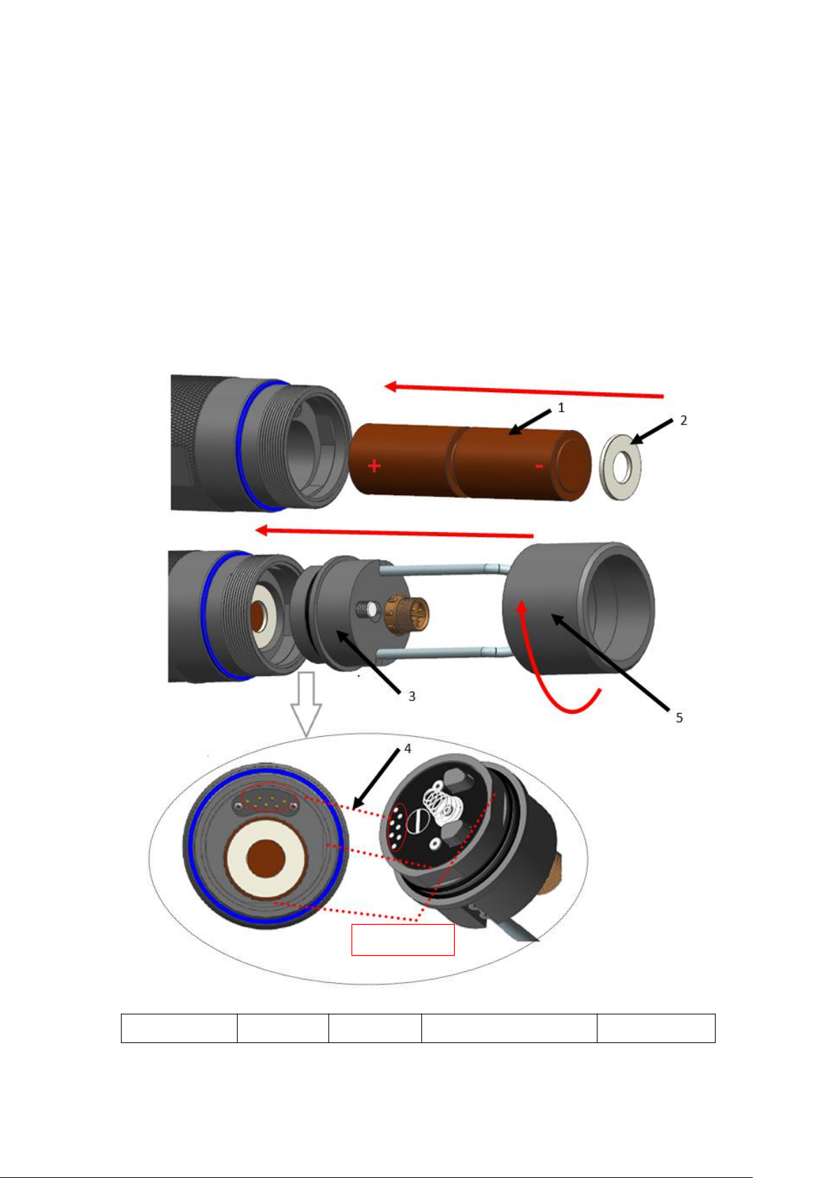
BQ401 Multi-parameter probe Battery Installation
The handheld multi-parameter probe requires two AA batteries for normal use. Please install the
batteries according to the following steps:
1) Rotate the tail cap counterclockwise to remove it, and pull out the tail plug.
2) Install two AA batteries and gaskets according to the schematic diagram, paying attention to the
positive and negative poles.
3) Install the tail plug and pay attention to the alignment of the data transmission interface with the
two positioning slots. Tighten the tail cap clockwise and the installation is complete.
1.Two AA batteries
2 . Gasket
3. Tale Plug
4. Data transmission interface
5. Tale Cover
Fixed groove

10
2.3 Connection
Cable connect to Instrument
As shown in the figure below, align the positioning red groove of the sensor cable connector with
the red groove on the meter connector, gently insert it, and then turn it clockwise until you hear
a "click" sound, and the connection is successful.
When the sensor probe is to be removed, first push the sensor cable connector inward, and then
turn it out counterclockwise.
Installation:
Take Off:
Align the positioning red groove of the sensor cable
connector with the red groove on the meter
Turn it clockwise until you
hear a "click" sound
First push the knurled lock
ring on the connector inward
Turn out counterclockwise

11
Probe Installation
Firstly, turn the probe removal tool counterclockwise from the top of the probe to take it out, as shown
in the figure below.
Insert the sensor into the port and carefully tighten the connecting nut clockwise by hand. If you feel
any resistance, loosen the connection nut completely and use the probe removal tool to tighten the
connection nut clockwise until it is snug. Insert the fixing ring and tighten the fixing screw clockwise.
Note: Do not over tighten the fixing screws. Over tightening may damage the sensor or the
retaining ring.
1. Probe
2.Plug
3.Main case
4. Probe connect nut
5.Probe removal tool
6. Fixed ring
7. Fixed screws
Take out pr obe:
Firstly, remove the fixing screw counterclockwise and pull out the fixing ring. Then insert the sensor
connection nut with the probe removal tool, and turn the fixing nut counterclockwise. After completely
loosening, pull the sensor directly out of the port and place it on a clean surface.
12
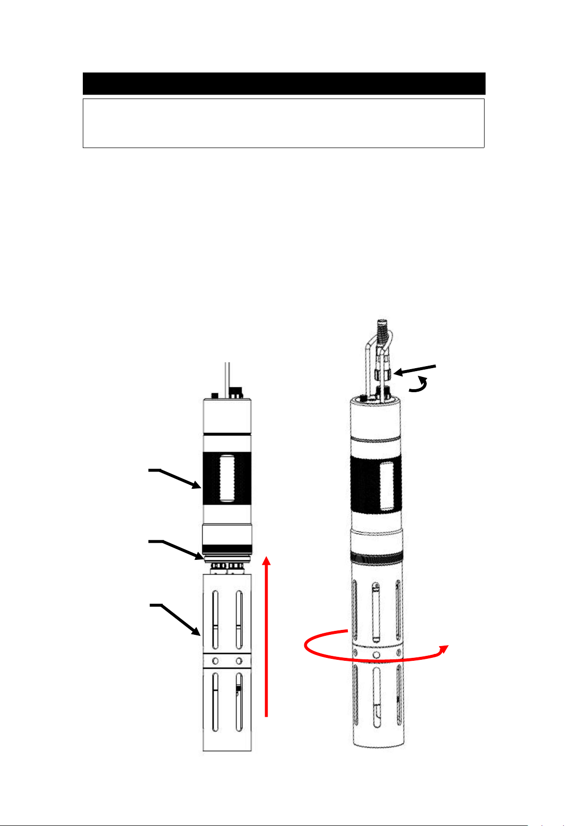
Sleeve installation and cable connection to the probe
1)Carefully push the sensor shield toward the main body until the threads of the sensor shield are
aligned with the threads of the main body.
2)Carefully tighten the sensor shield clockwise with your fingers.
3)Connect the cable to the sensor according to the schematic diagram, and tighten the connector
clockwise.
If a port is not installed with a probe, please install a plug. Otherwise exposure to water will cause
damage or corrosion of the connector
Attention
1
2
3
4
13
1. Protection cover
2. Thread
3. Main case
4.Cable probe port
3 Operation
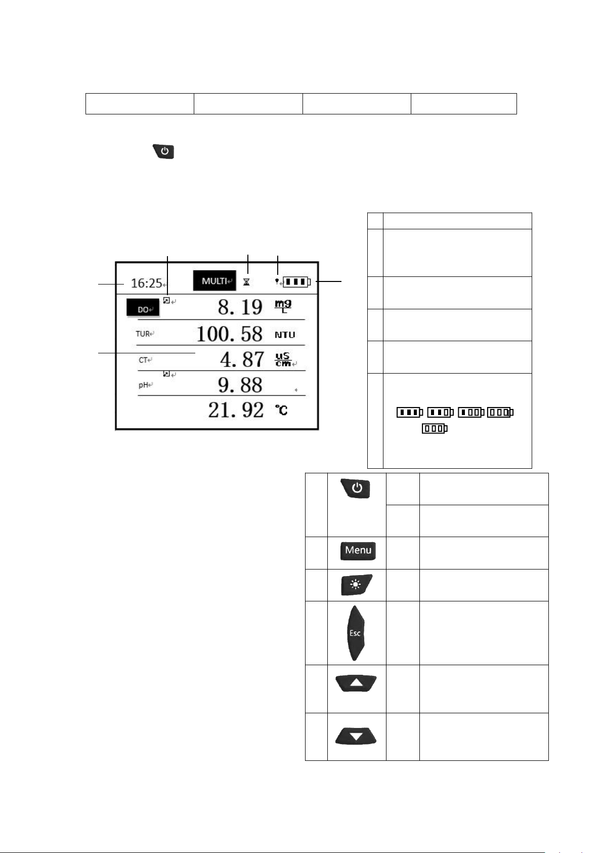
Short click button to turn on instrument ,BQ600 instrument supports hot-swappable
probe. When there is no probe, the measurement interface will display “No Signal!” after power on. If
the probe is inserted again, the measurement interface will display all the probe data, as shown in the
figure below
1
Time(Minutes:second)
2
Probe reading: 5 kinds of parameters
including measured temperature can
be displayed at the same time
3
Indicates that you can switch the
probe unit by pressing the OK key
4
Data is being recorded, with an
interval of 1 second
5
The meter battery is too low and will
be shut down soon
6
Battery status chart, indicating
battery level
If
show ,Directly charge the
instrument usb or remove the
rechargeable battery to charge.
1
Short
click
Turn on
Long
click
Turn off
2
Short
click
Enter to Menu page
3
Short
click
Back light open/off
4
Short
click
Exit settings;
Return to the previous
interface
5
Short
click
Scroll up to view menu
options
Increase value when setting
6
Short
click
Scroll down to view menu
options
Decrease value when setting
3
2
1
4
5
6

14
Button Instr uction
Measurement Display
7
Short
click
Enter the selected menu
Confirm the setting, save the
parameter value
Switch unit
8
Short
click
Enter the calibration
interface of the selected
probe
Long
click
Enter the calibration
recovery interface of the
selected probe
The measurement interface on the right
contains the parameters of 4 probes: DO,
turbidity, conductivity, and pH. The user can
press "▲" and "▼" to switch up and down to
select each probe. If there is a "" mark next to
the probe, press "↙" to switch the unit.
If the probe data exceeds the floating point
number range, the "ovf" mark will flash.
If "--" appears, it means that the probe is
disconnected or does not exist.
Short click:Button
less 2s
长按:按键大于 2S
15
Definition for parameters
DO
Dissolved Oxygen
SAL
Salinity
TUR
Turbidity
BGA
Blue-green Algae
CT
Conductivity
pH
pH
CHL
Chlorophyll
TSS
Total suspended solids
OIW
Oil in water
CDOM
Colored soluble organic
matter
Menu
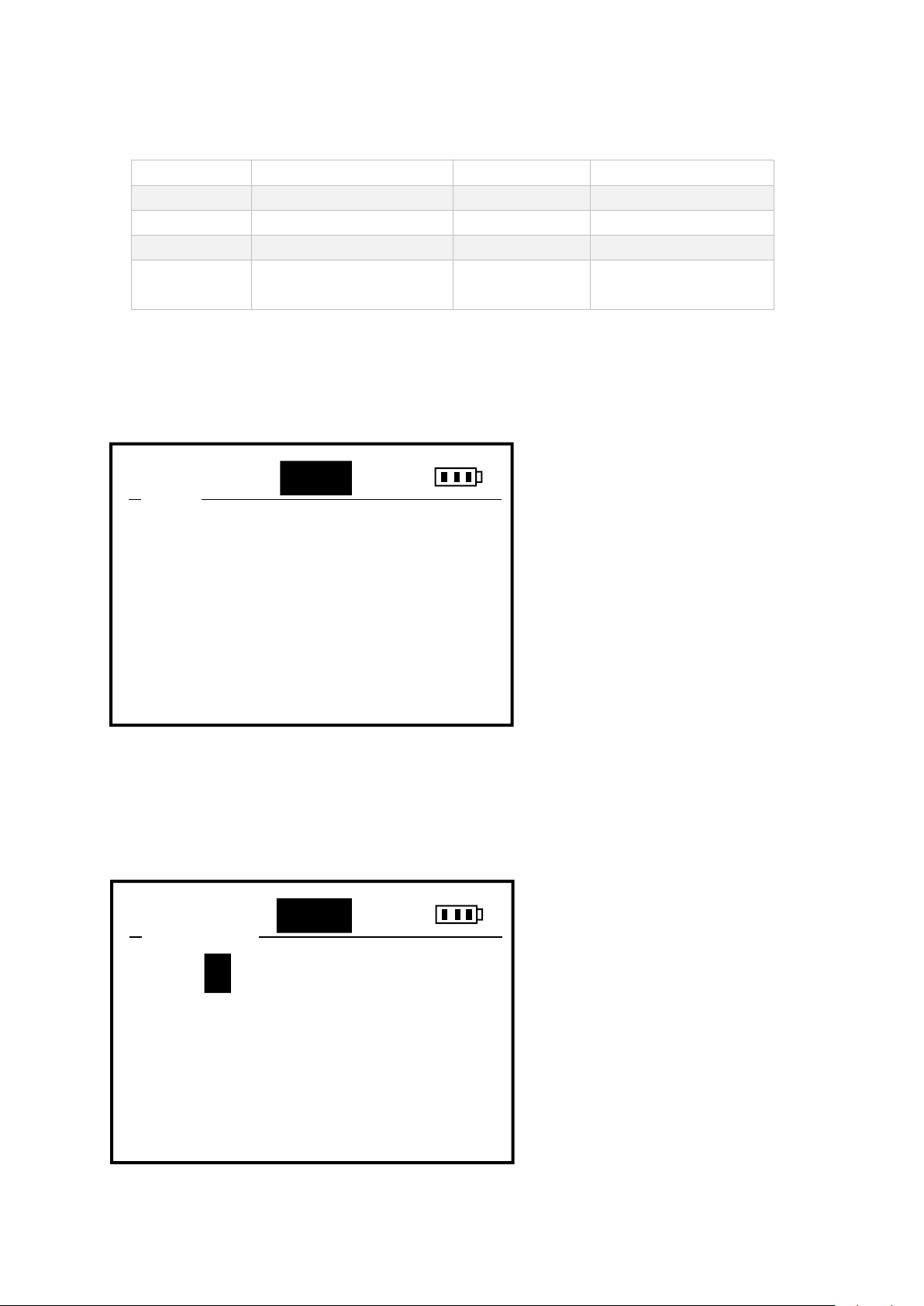
3.1 Date/Time
Press "Menu" to enter the menu
interface. Press the "▲▼" key to
highlight the menu option you have
selected, the "↙" key to enter the
selected sub-menu, and the "ESC" key
to exit the menu interface or menu
sub-interface.
The Date/Time menu sets the date
and time of the instrument. Use the
▲ and ▼ keys to adjust the current
value. Press "↙" to automatically
skip to the next value. After all
settings are completed, select Save
and press "↙" to save. A prompt
"Save Success!" will appear, which
means the save is successful.
Date/Time
System
Calibration
Data Log
11:25
Menu
MULT
I
Date:/ 09 / 19
Time: 15 : 10 : 07
Save
MULTI
11:25
Date/Time
19
16
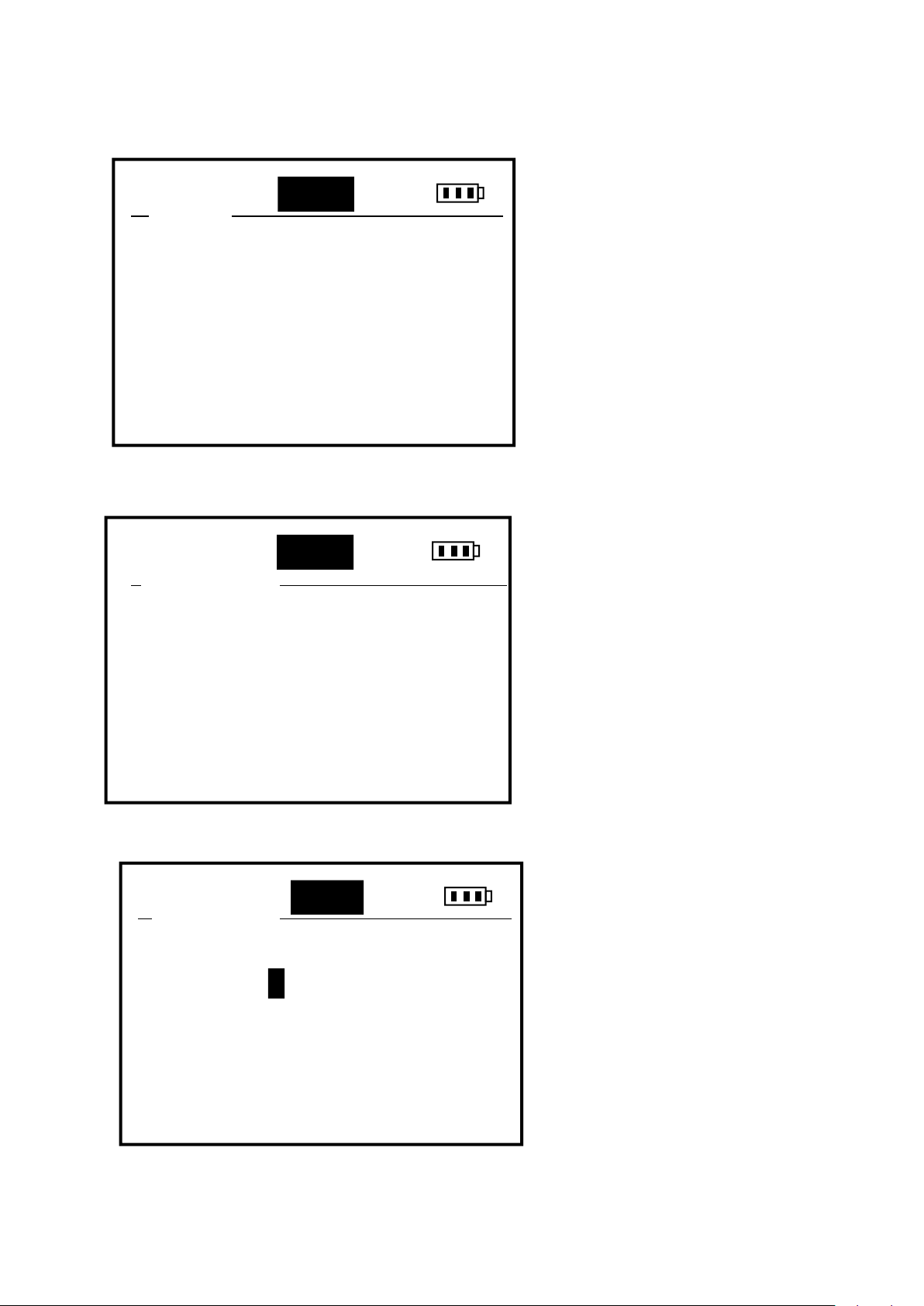
3.2 System
The System menu can query and set all
parameter information, including
automatic power off, atmospheric
pressure calibration, salinity value
setting, probe information, and
instrument information. Use "▲▼"
keys to select up and down, press "↙"
to enter the selected submenu
Auto Power
Four power states can be set:
OFF means the power is normally
open,
5min means the meter will
automatically shut down after 5
minutes of inactivity,
10min means the meter will
automatically shut down after 10
minutes of inactivity,
15min means the meter will
automatically shut down after 15
minutes of inactivity.
Use the "▲▼" key to select, and the
"↙" key to select. This setting will not
be saved when the power is off, and it
will automatically shut down in 5
minutes by default.
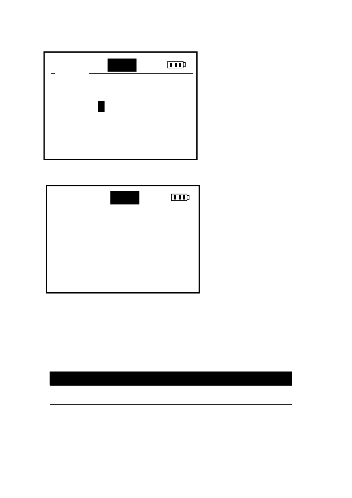
Air Pressure
The atmospheric pressure can be
calibrated in kPa, which will affect
the dissolved oxygen value. Current
represents the currently measured
atmospheric pressure value,
Standard represents the standard
atmospheric pressure to be
calibrated to, this value can be
adjusted with the ▲ and ▼ keys,
press "↙" to automatically skip to
the next value, save the value and
select Save and press "↙".
Current: 101.6
Standard: 000.0
Save
MULTI
11:25
Air Pressure
Auto Power
Air Pressure
Salinity
Probe Info
Meter Info
11:25
System
MULTI
OFF
5 min
10 min
15 min
11:25
Auto Power
MULTI
17
3.3 Calibration
Select a probe in the Menu->Calibration directory to enter the
calibration interface. You can also select a probe in the
measurement interface and press the "Cal" key to quickly enter the probe's calibration interface.
3.3.1 DO Calibration
The dissolved oxygen probe supports one-point calibration and two-point calibration. There is no zero
point calibration for dissolved oxygen.
Do not unplug the sensor cable during the entire calibration process.
Salinity
The salinity of the sample can be set.
As the salinity increases, the
dissolved oxygen value will decrease,
and the meter can compensate for the
deviation of the dissolved oxygen
value caused by the salinity value.
Use the ▲ and ▼ keys to adjust the
salinity value, press "↙" to
automatically skip to the next value,
save the value and select Save and
press "↙". This value can be saved
when power off, and the default
salinity is 0ppt. Usually 0-0.5ppt for
fresh water and 35ppt for sea water.
If there is a salinity probe, setting the
Probe Info
Including 4 probe options, select the
reverse display probe to view some
information of the probe, including
SN, hardware version number,
software version number, Modbus ID
address.
Meter Info
You can view some information of
the instrument, including SN,
hardware version number, and
software version number.
Unit:ppt
Current: 0.0
Input: 000..0
Save
MULTI
11:25
Salinity
5
SN: YL5019081516
HW VERSION: 1.1
SW VERSION: 2.0
ID: 01
11:25
Probe Info
MULTI
Attention

18
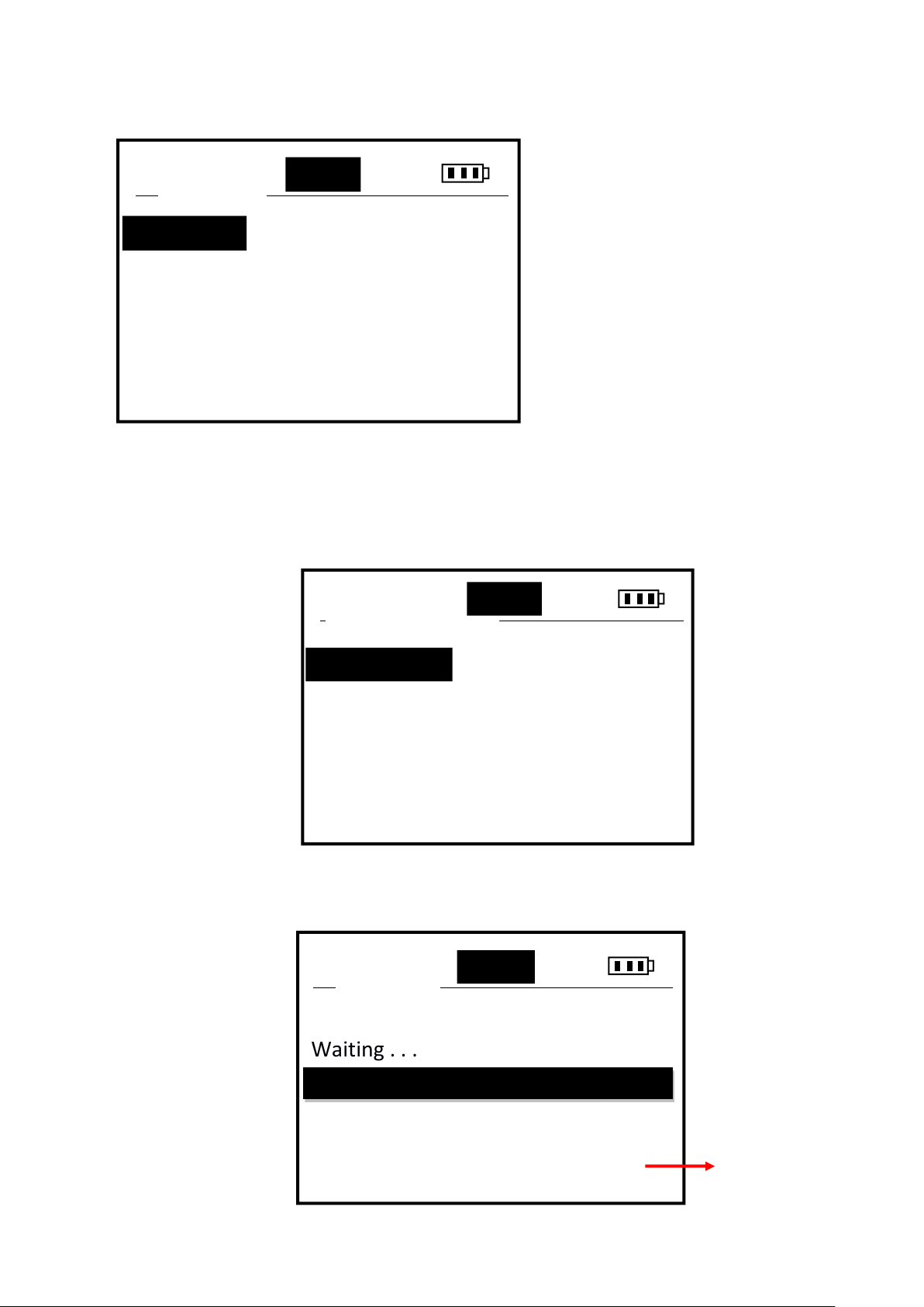
One point calibration
“STD Value”:Enter the target value to be calibrated, one point calibration, it is
recommended to set the target value of dissolved oxygen to 100% sat. Press the ▲ and ▼
keys to adjust the value, press "↙" to automatically skip to the next value.
“In STD Solution”: Press "↙" under "Click Enter" to enter the next step "In STD Solution",
which means that the dissolved oxygen electrode is placed in the dissolved oxygen environment
corresponding to the input value. The bottom of the screen will display the real-time measurement
value in %, waiting for the data to become Stable, as shown in the figure above.
“Confir m”:After stabilization, press "↙" under "Confirm", the meter calculates the slope, if it
prompts "Success", the calibration is successful, if it fails, it will prompt "Fail". After success,
press the "↙" key under "Cali Done!" to exit the calibration.
Before calibration, make sure to remove the protective cover of the DO electrode fluorescent cap
with a damp sponge on the probe.
Zero Point
Two Points
Sensor Cap
DO-Calibration
MULTI
One Point
Point
P
11:25
Attention
11:25
Real time
monitor value
STD Value:
100.0 %
In STD Solution
Waiting . . .
91.56
OnePoint
MULTI
Confirm

19
Two points Calibration
Firstly, enter the first calibration point for calibration, the process is the same as above, after
completion, press "↙" under "Click Enter" to enter the second point calibration. As shown below.
Follow the prompts: "STD Value" -> "In STD Solution" -> "Confirm", and enter the second target
value that needs to be calibrated. Put the electrode into the standard solution of the corresponding
value, wait for the data to stabilize and press the "↙" key, the meter calculates the zero point and
slope. If the calibration is successful, it will prompt “Success”, if it fails, it will prompt “Fail”.
Two points calibration for DO, suggest to choose 100% SAT for first point, 0% SAT for second
point.
Sensor Cap(Fluorescent cap parameter)
When replacing the fluorescent cap of a new electrode, you need to input the characteristic parameters
of the electrode cap correctly, otherwise the measurement data of the electrode will be inaccurate.
There are 8 sets of parameters K0-K7.
Zero oxygen environment: prepare a beaker, take 200ml tap water, distilled water, or negative ion water into
the cup, then slowly add anhydrous sodium sulfite to the beaker, stirring while adding, until the anhydrous
sodium sulfite is insoluble and solids appear. When the standard solution is zero oxygen.
Saturated oxygen environment: aerate the water with an aeration pump, and take out the aeration pump after 15
minutes. At this time, the water environment is a saturated oxygen environment.
*If conditions do not allow, it can be considered that the air is saturated with oxygen.
11:25
First point
calibration value
First Value:
100.0 %
In STD Solution
Success 93.64
93.64
TwoPoint
MULTI
Click Enter
20
3.3.2 Turbidity Calibration
Turbidity probe supports zero-point calibration, one-point
calibration and two-point calibration.
Zero point calibration
Select Read Para and press the "↙" key
to enter the read fluorescent cap
parameter interface. At this time, 8 sets
of K0-K7 data will appear.
Select Write Para and press the "↙"
key to enter the write fluorescent cap
parameter interface. At this time, 8 sets
of K0-K7 data will appear. Use the ▲
and ▼ keys to adjust each digit value,
press "↙" to automatically skip to the
next value. After all the updates are
completed, select Save and press "↙".
Write Para
11:25
Sensor Cap
MULTI
Read Para
One Point
Two Points
TUR-Calibratio
MULTI
Zero Point
Point
P
11:25
11:25
Real time
monitor value
In 0 NTU
Waiting . . .
1.21
ZeroPoint
MULTI
Confirm
Table of contents
Other BOQU Measuring Instrument manuals


Popular Measuring Instrument manuals by other brands

Kurt J. Lesker
Kurt J. Lesker 520TC Series Operation manual

Kobold
Kobold MIM Series operating instructions

SIAP+MICROS
SIAP+MICROS t011d TBAR User manual and maintenance

WYLER
WYLER CLINOMETER 80 quick reference

PRECISION DIGITAL
PRECISION DIGITAL Helios PD2-6060 instruction manual

Lutron Electronics
Lutron Electronics LM-81LX Operation manuals


