BOQU MS-301 User manual


MS-301 Multi parameter Water Quality Sensor Web:www.boquinstrument.com
Introduction
First of all, thanks for your trust and support by using BOQU integrated Multi parameter Water
Quality Sensor.
Before installation, please do read this manual carefully. For properly installing sensor and setting
parameters will maximize the performance and advantages of the product, to bring you a good
experience.
This instrument is a precision analytical measurement and control instrument, which should be
installed, operated and repaired by trained personnel or personnel who understand and have expertise in
this technique.
Please contact the after-sales department of BOQU Instrument, if you encounter difficulties during
installation or use.
After unpacking the box, please check the package list and the actual product you received. If there
is any missing or damaged, please contact BOQU Instrument in time.
We solemnly guarantee that:
1. If there are any quality problem occurs within one year from the date of purchase, you will be
served with product maintenance for free. Except the consumables
2. No matter where the product you buy from, the manufacturer hereby guarantees that you will be
served with lifetime technical maintenance and service.
3. Damage to the product caused by the following reasons shall not be covered by the warranty:
A. Damage caused by mistaken connection to high voltage power supply or water immersion;
B. Damage caused by unauthorized modification and misuse;
C. Incidental losses caused by improper selection of model;
D. Damage caused by the working conditions which exceeds that specified by the product;
E. All physical damage caused by improper force;
F. Failure to store and transport in accordance with the specified storage or transportation conditions
(reference to standard SJ/T10463-93); consumable materials should be purchased separately.
When this symbol appears in the manual, it refers to that it is related to safety, installation,
product function and use which should be paid special attention to.
Advancing with the times is the law of enterprise development, and the products will be upgraded in
stages. The general changes are subject to change without notice. Please refer to the actual product.

MS-301 Multi parameter Water Quality Sensor Web:www.boquinstrument.com
Table of Contents
Chapter 1 Product description ....................................................................................................................... 1
1.1 Products information ....................................................................................................................... 1
1.1.1 Integrated multi parameter water quality sensor .................................................................. 1
1.1.2 Hand manipulator(Optional) ................................................................................................ 1
1.2 Safety Information ...........................................................................................................................2
1.2.1 Use of dangerous information .............................................................................................. 3
1.2.2 Reminder prevention label ................................................................................................... 3
1.3 Pressure limit ...................................................................................................................................3
1.4 Temperature limit ............................................................................................................................ 4
1.5 Minimum depth requirement ...........................................................................................................4
Chapter 2 Introduction to Sensors .................................................................................................................4
2.1 Temperature Sensor ......................................................................................................................... 4
2.2 pH Sensor ........................................................................................................................................ 5
2.3 ORP Sensor ..................................................................................................................................... 6
2.4 Conductivity Sensor ........................................................................................................................ 7
2.4.1 Conductivity Sensor ............................................................................................................. 7
2.4.2 Salinity ..................................................................................................................................8
2.4.3 Total dissolved solids ........................................................................................................... 8
2.5 Dissolved Oxygen Sensor ............................................................................................................... 9
2.6 Turbidity Sensor ............................................................................................................................ 10
2.7 Depth Sensor ................................................................................................................................. 11
2.8 Chlorophyll sensor ........................................................................................................................ 12
2.9 Blue-green Algae Sensor ............................................................................................................... 13
2.10 Ammonia Nitrogen Sensor .......................................................................................................... 13
2.11 Nitrate ion sensor .........................................................................................................................14
2.12 Fluoride Ion Sensor ..................................................................................................................... 15
2.13 Chloride Ion Sensor .....................................................................................................................16
Chapter 3 Instrument Installation ................................................................................................................ 16

MS-301 Multi parameter Water Quality Sensor Web:www.boquinstrument.com
3.1 Instrument Unboxing .....................................................................................................................17
3.2 Starting the instrument .................................................................................................................. 17
3.3 Instrument connection ................................................................................................................... 17
3.3.1 Real-time online connection ...............................................................................................17
3.3.2 Portable Connection ........................................................................................................... 19
3.4 Installation Environment ............................................................................................................... 19
3.5 Installation Precautions ................................................................................................................. 19
Chapter 4 Real-time online setup and operation ......................................................................................... 20
4.1 Software installation ......................................................................................................................20
4.2 Software usage .............................................................................................................................. 20
4.2.1 Online data ......................................................................................................................... 21
4.2.2 Calibration .......................................................................................................................... 21
4.2.3 History data ........................................................................................................................ 22
4.2.4 System Settings .................................................................................................................. 23
4.2.4.1 Device settings ........................................................................................................ 23
4.2.4.2 Software Settings .....................................................................................................25
4.2.5 System Information ............................................................................................................ 25
Chapter 5 Setting and operation of hand manipulator .................................................................................26
5.1 Setting ............................................................................................................................................26
5.1.1 Setting of Bluetooth ............................................................................................................26
5.1.2 Sensor connection (choose one of two ways of connection between sensor connection and
Bluetooth connection) ................................................................................................................. 27
5.1.3 Sensor connection ...............................................................................................................27
5.1.4 Time setting ........................................................................................................................ 28
5.1.5 GPS .....................................................................................................................................29
5.2 Constant data ................................................................................................................................. 29
5.3 Historical data ................................................................................................................................29
Chapter 6 Calibration of Sensors .................................................................................................................30
6.1 Calibrate the sensor with software ................................................................................................ 30
6.1.1 Basic calibration process ....................................................................................................30

MS-301 Multi parameter Water Quality Sensor Web:www.boquinstrument.com
6.1.2 Temperature Sensor Calibration ......................................................................................... 31
6.1.3 pH Sensor Calibration ........................................................................................................ 32
6.1.4 ORP Sensor Calibration ..................................................................................................... 33
6.1.5 Conductivity Sensor Calibration ........................................................................................ 34
6.1.6 DO Dissolved Oxygen Calibration .....................................................................................36
6.1.6.1 Salinity compensation and temperature compensation ........................................... 37
6.1.7 Depth Sensor ...................................................................................................................... 37
6.1.8 Optical Sensor Calibration ................................................................................................. 38
6.1.8.1Turbidity Sensor Calibration .................................................................................... 38
6.1.8.2 Chlorophyll Sensor Calibration ...............................................................................41
6.1.8.3 Blue Green Algae Sensor ........................................................................................ 42
6.1.9 Ion Sensors Calibration ...................................................................................................... 44
6.1.9.1 Ammonia Nitrogen Sensor Calibration ................................................................... 44
6.1.9.2 Nitrate ion Sensor Calibration .................................................................................46
6.1.9.3 Fluorine Ion Sensor Calibration .............................................................................. 48
6.1.9.4 Chloride Ion Sensor Calibration ..............................................................................50
6.2 Calibrate the sensor by hand manipulator ..................................................................................... 52
6.2.1 Temperature calibration ......................................................................................................52
6.2.2 pH calibration ..................................................................................................................... 53
6.2.3 Conductivity calibration ..................................................................................................... 53
6.2.4 Dissolved oxygen calibration ............................................................................................. 54
6.2.5 Depth calibration ................................................................................................................ 54
6.2.6 Turbidity calibration ...........................................................................................................55
6.2.7 Chlorophyll calibration .......................................................................................................55
6.2.8 Blue-green algae calibration ...............................................................................................56
6.2.9 Fluoride ion calibration ...................................................................................................... 56
6.2.10 Chloride Ion Calibration ...................................................................................................57
6.2.11 Nitrate ion Calibration ...................................................................................................... 57
6.2.12 Ammonia Nitrogen Calibration ........................................................................................ 58
Chapter 7 Maintenance ................................................................................................................................58

MS-301 Multi parameter Water Quality Sensor Web:www.boquinstrument.com
7.1 Sensor maintenance .......................................................................................................................59
7.1.1 Temperature sensor maintenance ....................................................................................... 59
7.1.2 pH sensor maintenance .......................................................................................................59
7.1.3 Conductivity sensor maintenance .......................................................................................60
7.1.4 Dissolved oxygen sensor maintenance ...............................................................................60
7.1.5 Depth sensor maintenance ..................................................................................................61
7.1.6 Standard optical sensor maintenance ................................................................................. 61
7.1.7 Ion Sensor Maintenance ..................................................................................................... 61
7.2 Sensor Storage ...............................................................................................................................63
7.2.1 Short Storage ...................................................................................................................... 63
7.2.2 Long-term storage .............................................................................................................. 63
7.3 Cable maintenance ........................................................................................................................ 64
7.4 Sensor damage check .................................................................................................................... 64
7.5 Host battery replacement ...............................................................................................................64
Chapter 8 Communication Protocol ............................................................................................................ 65
Chapter 9 Problems and Solutions .............................................................................................................. 82

MS-301 Multi parameter Water Quality Sensor Web:www.boquinstrument.com
Chapter 1 Product description
1.1 Products information
1.1.1 Integrated multi parameter water quality sensor
The BOQU integrated multi parameter water quality sensor is a monitoring instrument for long-term field
use. It can select 2-7 parameters and realize simultaneous real-time online monitoring, data reading and
storage functions of temperature, depth, pH, ORP, conductance, turbidity, dissolved oxygen, chlorophyll,
blue-green algae, ammonia nitrogen, Nitrate ion, fluoride ion and chloride ion. Each sensor measures its
own parameters through a variety of electrochemical, optical or physical means of detection.
The integrated multi parameter water quality sensor can be equipped with self-cleaning system to obtain
accurate data for a long time, and with different lengths of cable to meet customer needs, easy to operate,
accurate data. It is widely used in online monitoring of water quality in different water bodies such as
rivers, lakes, reservoirs, drinking water, groundwater and seawater (optional). The external dimensions of
the integrated multi parameter water quality sensor are shown in Figure 1.
Figure 1 multi parameter water quality sensor
1-Outer shell
2-Cable
3-Waterproof joint
4-Battery cover
5-Battery cover
6-Calibration cup
The technical parameters of the integrated multi parameter water quality sensor host are shown in the
following table.:

MS-301 Multi parameter Water Quality Sensor Web:www.boquinstrument.com
Host specification
Voltage
12VDC
Power consumption
3 W
communication
MODBUS RS485
Maximum withstand pressure
Normal electrode:30 meter Ion electrode:10meter
Operating temperature
0~45 °C (not frozen)
storage temperature
0~50 °C(not frozen)
Protection level
IP68
Weight About
3 kg
Battery capacity
8 units, 8C, 3.6v lithium battery
1.1.2 Hand manipulator(Optional)
Specially designed for the customers, BOQU Instrument researches and develops a hand manipulator to
make integrated multi parameter water quality sensor complete the data reading, parameter setting, and
calibration without the using of PC, and can be fit for being held in hand easily for any situation.
The hand manipulator can constantly read and display the data of integrated multi parameter water quality
sensor on line, and can read and export the history data (only can read and export history data stored by
hand manipulator). Also, hand manipulator can complete the parameter setting and calibration for the
sensor. The inside GPS acceptor can establish a one-to-one relationship between the data group measured
each time and the geographic location information from GPS positioning system. Bluetooth function
makes the hand manipulator communicate with multi-parameter sensor directly and conveniently without
cables connection. The storage function makes history data stored by multi parameter water quality sensor
be exported and read with special setting. USB interface can realize the power supply for built-in battery
and the exporting of data. Ergonomic curve design with rubber gasket makes hand-holding operation easy
and be suitable for mastering in the humid environment. Appearance dimension diagram is showed in
Diagram two as below.

MS-301 Multi parameter Water Quality Sensor Web:www.boquinstrument.com
Figure 2 dimension diagram of hand manipulator
The technology parameters of hand manipulator have been showed as below:
Display
3.5-inch color display screen with adjustable backlight
Data Storage
8G
Power supply
Internal battery power supply,
Battery Specification: 4 Section 3.7 V Lithium Battery
Protection Level
IP67
Operating Temp.
0~50℃(not frozen)
Storage Temp.
-15~60℃(not frozen)
Size
203*100*43mm
Weight
0.5KG
1.2 Safety Information
Please read this manual thoroughly before unpacking, setting up or operating the instrument.
Pay special attention to all hazard and warning statements. In the event of mishandling, it may cause
serious injury to the operator or damage to the equipment.
This equipment must be used and installed only in accordance with the detailed instructions in this
manual.
MS-301 Multi parameter Water Quality Sensor Web:www.boquinstrument.com
1.2.1 Use of dangerous information
For various hazards, this manual will use signal specific words (Danger, Caution, Note) that correspond to
the degree of danger.
Danger
Indicates a potentially or imminently dangerous state that, if not prevented, could be life-threatening or
cause serious injury.
caveat
Indicates a potentially dangerous state that may cause mild or moderate injury.
Important note: Information that requires special emphasis.
Tip: Information in the text that supplements the points
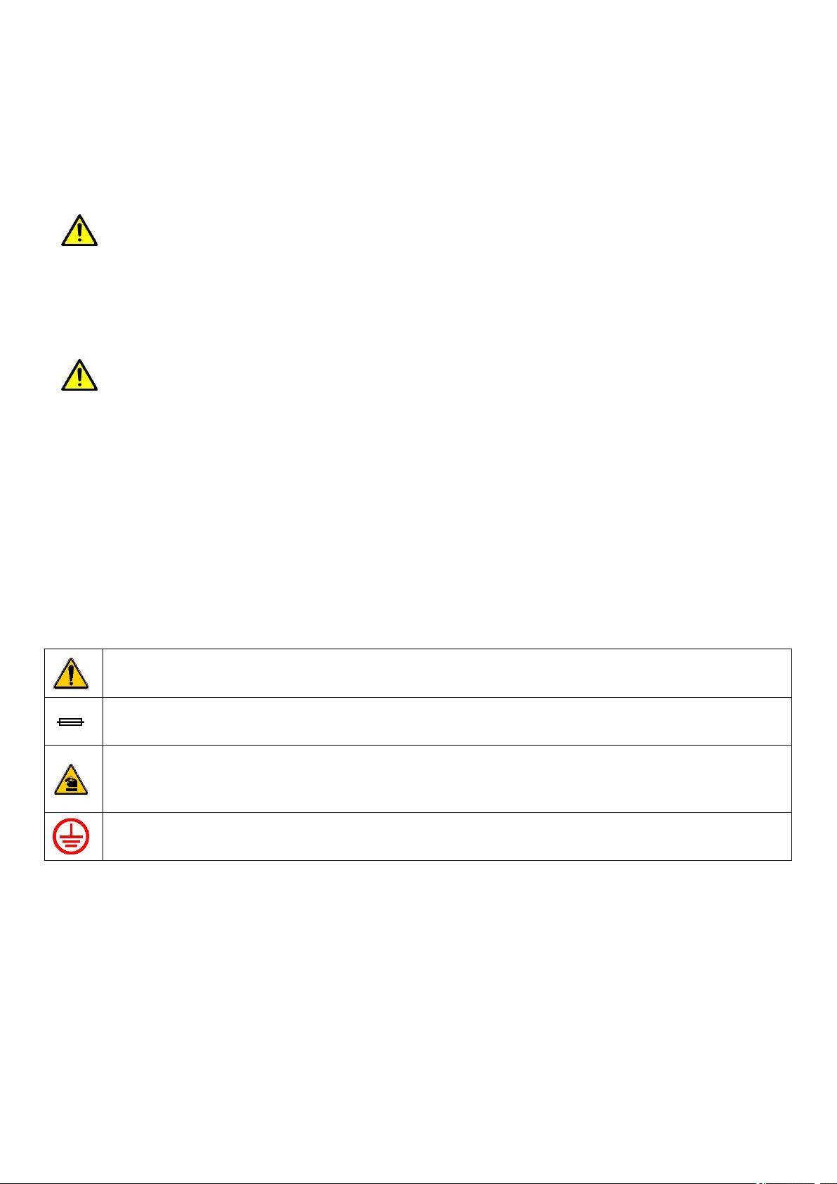
1.2.2 Reminder prevention label
Carefully read all the labels and identifiers attached to the instrument, otherwise it may cause personal
injury or damage to the instrument.
If the label is marked on the instrument, refer to the instrument manual for operation and/or safety information.
If the label is marked on the product, it indicates that there is a fuse or current limiting device.
If the label is marked on the product, it indicates that the device is susceptible to static electricity leakage
and protective measures should be taken to prevent damage.
If the label is marked on the product, it indicates the location of the ground wire.
1.3 Pressure limit
The maximum immersion pressure of the multi-parameter Sensor is 0.3Mpa or less. When the underwater
Sensor pressure is greater than 0.3Mpa, the sensor will be mechanically damaged and
deformed(Note: If choose ion electrode, the max. immersion pressure should be less than 0.1Mpa. )

MS-301 Multi parameter Water Quality Sensor Web:www.boquinstrument.com
1.4 Temperature limit
When storing a multi-parameter Sensor, the multi-parameter Sensor stores a temperature range of 0 to
50°C, non-freezing. The multi-parameter Sensor operates over a temperature range of 0 to 45°C and is not
frozen. Exposing a multi-parameter Sensor outside of the above temperature range may result in
mechanical damage and electrical failure.
To prevent freezing of the multi-parameter Sensor.
1.5 Minimum depth requirement
In order to prevent the sun exposure sensor, the sensor body must be completely submerged by water
when in use.
Chapter 2 Introduction to Sensors
The integrated multi parameter water quality sensor measures the following parameters: depth,
temperature, pH, ORP, conductivity, turbidity, dissolved oxygen, chlorophyll, blue-green algae, ammonia
nitrogen, nitrate, fluoride and chloride. The wide range of physical, biological and chemical properties of
natural waters can be monitored.
Please note: That pH, Conductance, ORP, Ammonia nitrogen, Nitrate ion, fluoride ion, chloride ion, these
seven parameters are analog electrodes, up to 4 can be selected but can’t be repeated, the corresponding
host interface is fixed, can’t be universal .
And when the electrode parameter configuration is selected, are factory-set, even if the corresponding
electrode is not connected in the field, the host can’t prompt that the electrode is not connected, but will
still have a value. In this case, the output value is an arbitrary value, and not accurate value of
measurement. So when using, please make sure the corresponding electrode is connected!
2.1 Temperature Sensor
Principle:
MS-301 Multi parameter Water Quality Sensor Web:www.boquinstrument.com
Temperature is a measure of the amount of heat present in a body of water, and temperature is considered
to be a very important single parameter. It affects other parameters of water quality and controls the
metabolism of aquatic animals and plants.
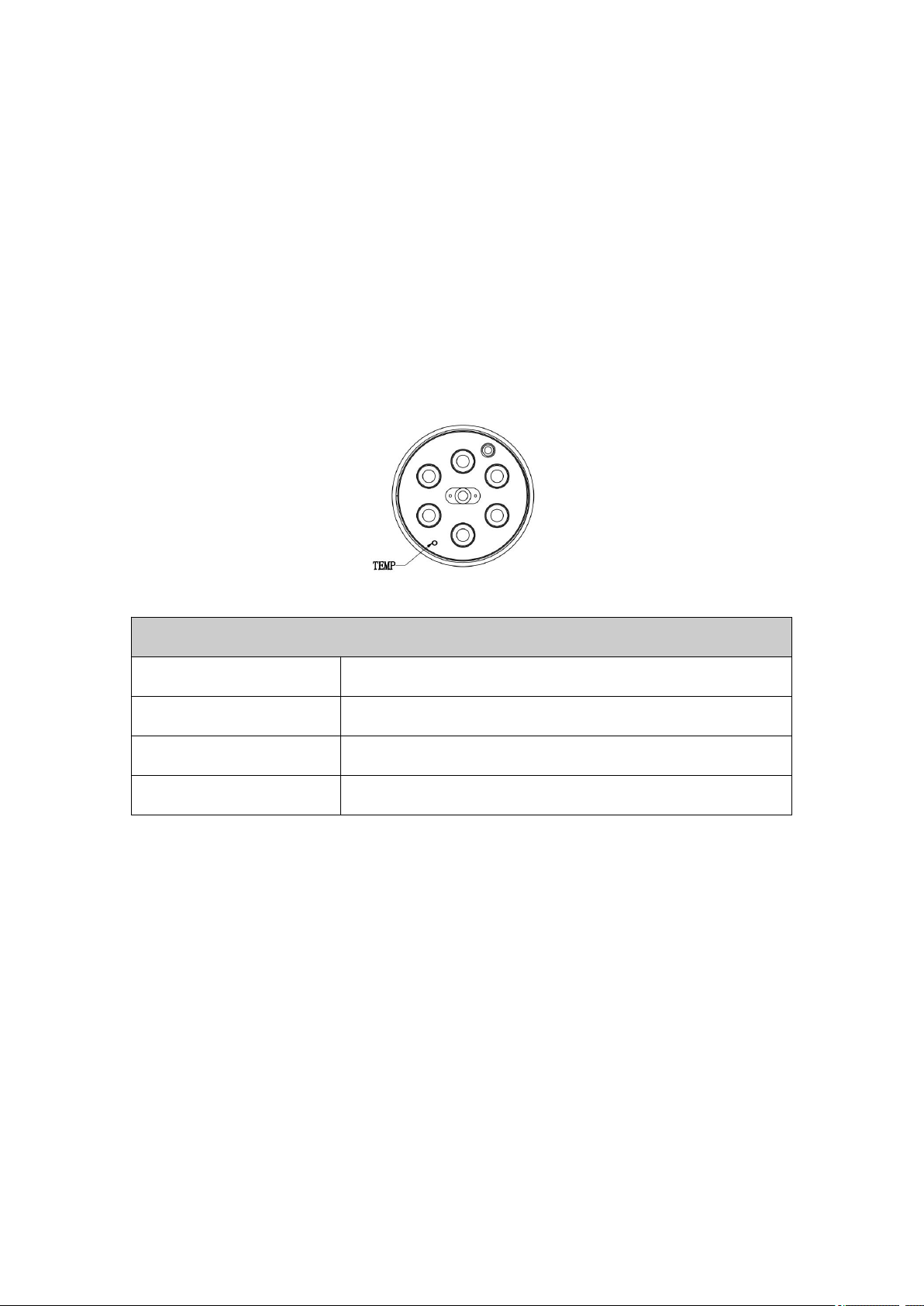
The integrated multi parameter water quality sensor uses a thermistor to measure the temperature of the
water. The resistance value of the thermistor changes with temperature, and the measured resistance value
can be converted into a temperature value using a corresponding calculation formula. This formula has
been built into the host software, and the user can directly view the real-time Celsius. The appearance of
the temperature sensor is shown in Figure 3.
Figure 3 Temperature sensor
Temperature Sensor Specification
Principle
Thermistor method
Range
0~50 °C
Resolution
0.01 °C
Accuracy
± 0.5 °C
2.2 pH Sensor
Principle:
pH describes the pH and basic properties of a water body. It is acidic when pH<7.0, neutral when pH=7.0,
and alkaline when pH>7.0.
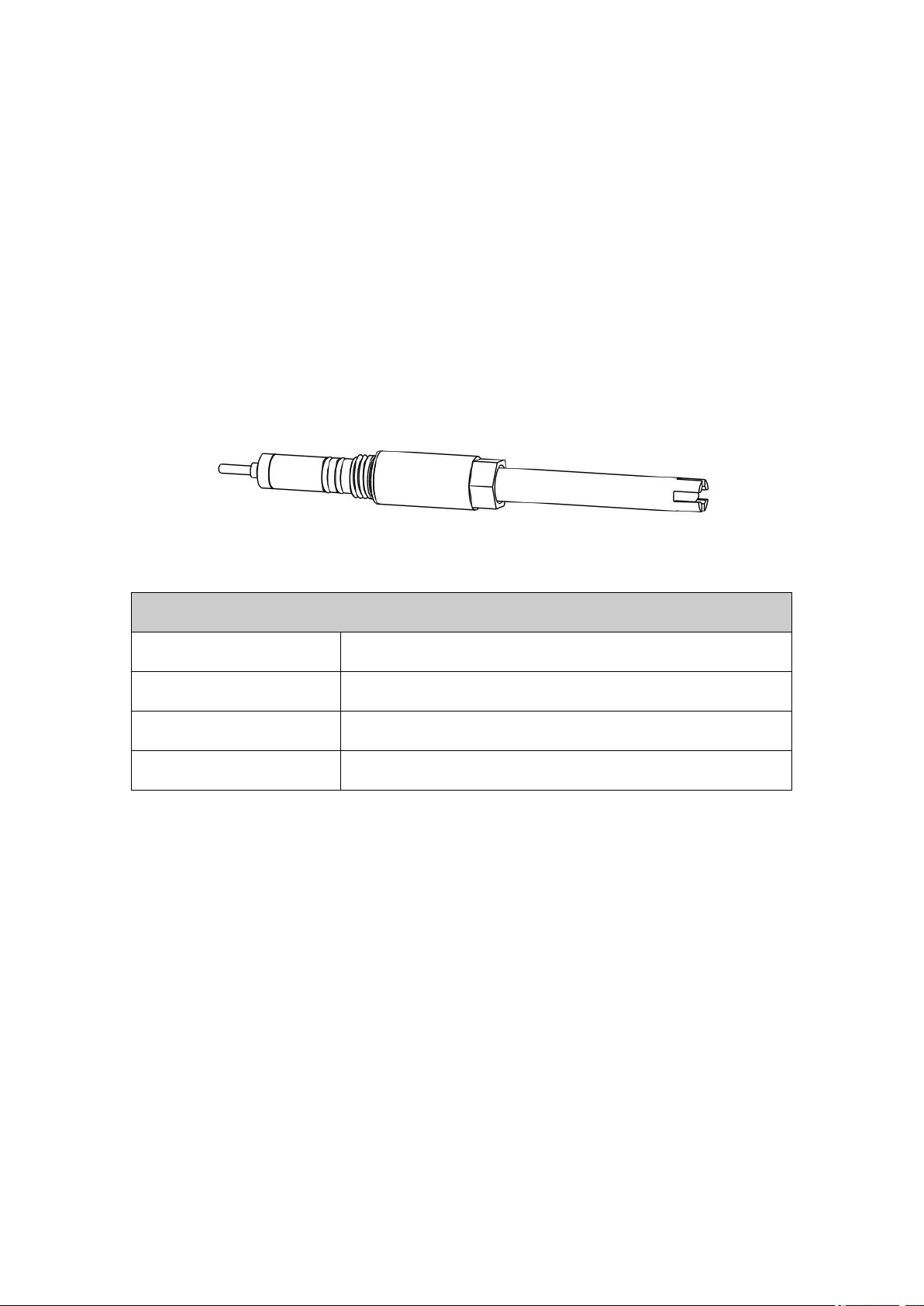
The pH sensor uses a glass electrode method to measure the pH of the water. The sensor consists of two
parts, including a glass bubble containing a glass film that selectively responds to H+, a glass foam
containing a 0.1 mol/L HCl internal reference solution, and an internal reference electrode Ag- AgCl
electrode. When the electrode is immersed in the solution to be tested, the difference between the stable
potential of the reference electrode and the potential generated by the glass sphere is proportional to the
H+ concentration in the solution.
MS-301 Multi parameter Water Quality Sensor Web:www.boquinstrument.com
The pH sensor measures data with stability, reliable performance and easy installation. The appearance of
the pH sensor is shown in Figure 4.
Important Tip1: When using a new pH electrode, the electrode should be immersed in distilled water for a
period of time, usually 24 hours or more, in order to form a good hydration layer. There should be no air
bubbles between the bulbs of the inner electrodes of the glass electrodes, and if there are bubbles, the
bubbles can escape easily.
Important Tip 2: Provided the pH is used in high sulfur ion environments, which is easy damaged and
with short life time.
Figure 4 pH Sensor
pH Sensor Specification
Principle
Glass electrode method
Range
0-14 pH
Resolution
0.01 pH
Accuracy
±0.1 pH
2.3 ORP Sensor
Principle:
ORP sensor is a composite electrode in which the indicator electrode and the reference electrode are
combined. Also known as REDOX electrode. The data is stable and reliable.
The appearance of the ORP sensor is shown in Figure 5.
IMPORTANT: When using the new ORP electrode, the electrode should be immersed in distilled water
for a period of time, usually more than 24 hours, in order to form a good hydration layer. There should be
no air bubbles between the bulbs of the inner electrodes of the glass electrodes, and if there are bubbles,
the bubbles can escape easily.

MS-301 Multi parameter Water Quality Sensor Web:www.boquinstrument.com
Figure 5 ORP Sensor
ORP Sensor Specification
Principle
Glass electrode method
Range
-1000mV~1000 mV
Resolution
0.01mV
Accuracy
±0.1 mV
2.4 Conductivity Sensor
2.4.1 Conductivity Sensor
Principle:
Conductivity indicates the electrical conductivity of a substance. The greater the conductivity, the greater
the conductivity and vice versa.
The conductivity sensor is a combination of two parallel plates. When it is placed in the solution to be
tested and a certain potential (usually a sinusoidal voltage) is applied across the plates, the interpolate
flow can be measured. The current passed. The conductivity of the water quality is calculated according
to the corresponding calculation formula.
The company has designed two conductivity sensors with different ranges: 1 μS/cm-2000 μS/cm (k=1)
and 100 μS/cm-100 mS/cm (k=10.0), users can follow their own The different requirements are selected.
The specific parameters can be found in the technical specifications below, where K represents the
electrode constant.
Conductivity Sensors not only test conductivity, but also convert to salinity and total dissolved solids.
Another salinity can be used for real-time compensation of dissolved oxygen. The appearance of the
conductivity sensor is shown in Figure 6

MS-301 Multi parameter Water Quality Sensor Web:www.boquinstrument.com
Figure 6 Conductivity Sensor
Conductivity Sensor Specification
Principle
Platinum electrode
Range
1 μS/cm-2000 μS/cm (k=1)
100 μS/cm- 100 mS/cm (k=10.0)
Resolution
0.1 μS/cm- 0.01 mS/cm (Related to Range)
Accuracy
±3%
2.4.2 Salinity
Salinity is a measure of the total amount of salt dissolved in a body of water. It can be automatically
calculated from the conductivity and temperature detected by the multi parameter water quality sensor.
The algorithm is based on the standard method for water and seawater detection (1989), and its unit
output is ppt. Salinity can be used for real-time compensation of dissolved oxygen.
Salinity Specification
Principle
Converted by conductivity
Range
0-1 ppt (k=1.0) ;0-70 ppt (k=10.0)
Resolution
0.001ppt~0.01ppt(Related to Range)
Accuracy
±3%
2.4.3 Total dissolved solids
The total dissolved solids are also called the total amount of dissolved solids, which means the amount of
materials dissolved in water or small enough to be filtered, which can be used to reflect the degree of
pollution of water bodies. The ionic species dissolved in the water causes the water to be electrically
conductive, so the amount of the compound in which the ions are present can be roughly estimated by the

MS-301 Multi parameter Water Quality Sensor Web:www.boquinstrument.com
conductivity, and the output unit is ppm.
Because the chemical composition of different water bodies causes different ionic properties, the
conductivity cannot fully calculate the amount of TDS.
TDS Sensor Specification
Principle
Converted by conductivity
Range
0-1000 mg/L(K=1)
50-500000 mg/L(K=10.0)
Resolution
0.1 mg/L ~1 mg/L(Related to Range)
Accuracy
±3%
2.5 Dissolved Oxygen Sensor
Principle:
Dissolved oxygen is a measure of the amount of oxygen present in a body of water and is usually referred
to as DO. The dissolved oxygen sensor is measured by fluorescence method. The top of the sensor is
covered with a layer of fluorescent substance. When the blue light emitted by the sensor is irradiated to
the fluorescent substance, the fluorescent substance is excited to emit red light, and the oxygen molecule
can carry away energy (quenching effect). Therefore, the time and intensity of the excited red light is
inversely proportional to the concentration of oxygen molecules, and the concentration of dissolved
oxygen in the water can be obtained by calculation. The appearance of the dissolved oxygen sensor is
shown in 7.
Measurement / Interference:
1. When measuring, the air bubbles attached to the film must be avoided.
2. The presence of chlorine can distort the measurement results (overestimating the dissolved oxygen
level).
3. After the sensor is inserted into the measurement environment, wait for the sensor temperature to
stabilize before starting measurement.
Safety Cautions
Hazardous film factors are: chemicals (organic solvents, acids and peroxides); mechanical damage (impac
t, friction or tear)

MS-301 Multi parameter Water Quality Sensor Web:www.boquinstrument.com
Figure 7 Dissolved Oxygen Sensor
DO Sensor Specification
Principle
Fluorescence method
Range
0-20 mg/L;0-20 ppm;0-200%
Resolution
0.1%/0.01mg/L
Accuracy
±3% or ±0.3mg/l of Measured Value ,take the greater
value
2.6 Turbidity Sensor
Principle:
Turbidity is the measure of the amount of suspended solids in water. Suspended solids in water are
generally clay, sand, colloidal matter, algae, plankton and microorganisms.
The turbidity sensor is designed based on a combined infrared absorption scatter ray method. The infrared
light emitted by the light source is scattered by the particles in the water to be measured, converted into
an electrical signal by a photo detector, and subjected to analog and digital signal processing to obtain a
turbidity value of the water sample. A turbidity unit NTU having a basic turbidity standard using formalin
(a white polymer produced by polymerization of a certain amount of barium sulfate and hexamethylamine)
is usually used. The turbidity sensor is shown in Figure 8.
Figure 8 Turbidity Sensor
Turbidity Sensor Specification

MS-301 Multi parameter Water Quality Sensor Web:www.boquinstrument.com
Principle
Light scattering
Range
0-1000 NTU
Resolution
0.1 NTU
Accuracy
±5% or ±0.3NTU,take the greater value
2.7 Depth Sensor
Principle:
The depth sensor uses a pressure sensitive method to measure the depth of the water. One side of the
sensor faces the other side of the water facing the vacuum to measure the pressure. The depth is then
calculated by subtracting the atmospheric pressure from the pressure applied by the water body. The
distance from the depth sensor to the liquid surface is the measurement distance.
Reasons that affect depth measurements include atmospheric pressure, water density, and temperature.
Due to differences in atmospheric pressure at different times and in different regions, the software uses
atmospheric pressure at the time of calibration, which may result in small errors. Therefore, depth sensor
calibration is required before use (see 6.1.7 Depth Sensor Calibration). Frequent calibration can reduce
the error. The appearance of the depth sensor is shown in Figure 9.
Figure 9 Depth sensor
Depth Sensor Specification
Principle
Pressure Sensitive Method

MS-301 Multi parameter Water Quality Sensor Web:www.boquinstrument.com
Range
0-61 m
Resolution
2 cm
Accuracy
±0.3%
2.8 Chlorophyll sensor
Principle:
Chlorophyll is an important biochemical molecule that is the basis of photosynthesis and uses solar
energy to produce oxygen. The concentration of suspended phytoplankton can usually be calculated by
collecting the amount of chlorophyll in the water sample.
The chlorophyll sensor in utilizes the characteristic that chlorophyll A has absorption peak and emission
peak in the spectrum. Monochromatic light emitting a specific wavelength is irradiated into water, and
chlorophyll A in water absorbs the energy of the monochromatic light, releasing another wavelength. The
monochromatic light, the light intensity emitted by chlorophyll A is proportional to the amount of
chlorophyll A in the water. From this, the concentration of chlorophyll in the water body was calculated.
The appearance of the chlorophyll sensor is shown in Figure 10.
Figure 10 Chlorophyll sensor
Chlorophyll sensor Specification
Principle
Fluorescence method
Range
0-500 μg/L
Resolution
0.1 μg/L
Accuracy
The signal level of 1ppb rhodamine WT dye corresponds
to ±10% of the value(At the same temperature)

MS-301 Multi parameter Water Quality Sensor Web:www.boquinstrument.com
2.9 Blue-green Algae Sensor
Principle:
Blue-green algae, also known as cyanobacteria, is a widely distributed prokaryotic microorganism that is
closely related to the environmental quality of water bodies. When the water body grows vigorously, it
will cause discoloration and odor.
The blue-green algae sensor utilizes the characteristic that the cyanobacteria has an absorption peak and
an emission peak in the spectrum, and a monochromatic light emitting a specific wavelength is irradiated
into the water, and the cyanobacteria in the water absorbs the energy of the monochromatic light,
releasing a single wavelength single. The color of light, the light intensity emitted by blue-green algae is
proportional to the content of cyanobacteria in the water. The appearance of the blue-green algae sensor is
shown in Figure 11.
Figure 11 Blue-green algae Sensor
Blue-green algae Sensor Specification
Principle
Fluorescence method
Range
200-300000 cells/mL
Resolution
20 cells/mL
Accuracy
The signal level of 1ppb rhodamine WT dye corresponds
to ±10% of the value(At the same temperature)
2.10 Ammonia Nitrogen Sensor
The NH4 ion selective electrode is a grid film electrode ,the material of which mainly uses a special
organic ion exchange membrane that dissolves in the organic solution and penetrates with the PVC mesh.
The fields it is widely used include: drinking water, fertilizer, and refrigerant. To use the electrode
requires the reference electrode, it has good repeatability and faster response time, but its accuracy is no
better than the colorimetric method. The outer appearance of the ammonia nitrogen sensor is shown in
Table of contents
Other BOQU Measuring Instrument manuals


